EP0932534B1 - Gelenkverbindung - Google Patents
Gelenkverbindung Download PDFInfo
- Publication number
- EP0932534B1 EP0932534B1 EP98949918A EP98949918A EP0932534B1 EP 0932534 B1 EP0932534 B1 EP 0932534B1 EP 98949918 A EP98949918 A EP 98949918A EP 98949918 A EP98949918 A EP 98949918A EP 0932534 B1 EP0932534 B1 EP 0932534B1
- Authority
- EP
- European Patent Office
- Prior art keywords
- bearing
- hinge joint
- joint according
- hollow
- hollow body
- Prior art date
- Legal status (The legal status is an assumption and is not a legal conclusion. Google has not performed a legal analysis and makes no representation as to the accuracy of the status listed.)
- Expired - Lifetime
Links
- 239000000463 material Substances 0.000 claims description 11
- 239000002184 metal Substances 0.000 claims description 10
- 125000006850 spacer group Chemical group 0.000 claims description 7
- 238000007789 sealing Methods 0.000 claims description 5
- 229910000831 Steel Inorganic materials 0.000 claims description 2
- 239000010959 steel Substances 0.000 claims description 2
- 230000001681 protective effect Effects 0.000 description 6
- 238000005507 spraying Methods 0.000 description 4
- 210000003128 head Anatomy 0.000 description 3
- 238000000034 method Methods 0.000 description 3
- 235000012569 Ficus capensis Nutrition 0.000 description 1
- 244000113426 Ficus capensis Species 0.000 description 1
- 230000004323 axial length Effects 0.000 description 1
- 238000005452 bending Methods 0.000 description 1
- 230000008878 coupling Effects 0.000 description 1
- 238000010168 coupling process Methods 0.000 description 1
- 238000005859 coupling reaction Methods 0.000 description 1
- 238000004519 manufacturing process Methods 0.000 description 1
- 230000003287 optical effect Effects 0.000 description 1
Images


Classifications
-
- F—MECHANICAL ENGINEERING; LIGHTING; HEATING; WEAPONS; BLASTING
- F16—ENGINEERING ELEMENTS AND UNITS; GENERAL MEASURES FOR PRODUCING AND MAINTAINING EFFECTIVE FUNCTIONING OF MACHINES OR INSTALLATIONS; THERMAL INSULATION IN GENERAL
- F16C—SHAFTS; FLEXIBLE SHAFTS; ELEMENTS OR CRANKSHAFT MECHANISMS; ROTARY BODIES OTHER THAN GEARING ELEMENTS; BEARINGS
- F16C11/00—Pivots; Pivotal connections
- F16C11/04—Pivotal connections
-
- B—PERFORMING OPERATIONS; TRANSPORTING
- B60—VEHICLES IN GENERAL
- B60S—SERVICING, CLEANING, REPAIRING, SUPPORTING, LIFTING, OR MANOEUVRING OF VEHICLES, NOT OTHERWISE PROVIDED FOR
- B60S1/00—Cleaning of vehicles
- B60S1/02—Cleaning windscreens, windows or optical devices
- B60S1/04—Wipers or the like, e.g. scrapers
- B60S1/06—Wipers or the like, e.g. scrapers characterised by the drive
- B60S1/16—Means for transmitting drive
- B60S1/18—Means for transmitting drive mechanically
-
- B—PERFORMING OPERATIONS; TRANSPORTING
- B60—VEHICLES IN GENERAL
- B60S—SERVICING, CLEANING, REPAIRING, SUPPORTING, LIFTING, OR MANOEUVRING OF VEHICLES, NOT OTHERWISE PROVIDED FOR
- B60S1/00—Cleaning of vehicles
- B60S1/02—Cleaning windscreens, windows or optical devices
- B60S1/04—Wipers or the like, e.g. scrapers
- B60S1/06—Wipers or the like, e.g. scrapers characterised by the drive
- B60S1/16—Means for transmitting drive
- B60S1/18—Means for transmitting drive mechanically
- B60S1/24—Means for transmitting drive mechanically by rotary cranks
-
- B—PERFORMING OPERATIONS; TRANSPORTING
- B60—VEHICLES IN GENERAL
- B60S—SERVICING, CLEANING, REPAIRING, SUPPORTING, LIFTING, OR MANOEUVRING OF VEHICLES, NOT OTHERWISE PROVIDED FOR
- B60S1/00—Cleaning of vehicles
- B60S1/02—Cleaning windscreens, windows or optical devices
- B60S1/04—Wipers or the like, e.g. scrapers
- B60S1/32—Wipers or the like, e.g. scrapers characterised by constructional features of wiper blade arms or blades
- B60S1/34—Wiper arms; Mountings therefor
- B60S1/3402—Wiper arms; Mountings therefor with means for obtaining particular wiping patterns
- B60S1/3409—Wiper arms; Mountings therefor with means for obtaining particular wiping patterns the wiper arms consisting of two or more articulated elements
-
- F—MECHANICAL ENGINEERING; LIGHTING; HEATING; WEAPONS; BLASTING
- F16—ENGINEERING ELEMENTS AND UNITS; GENERAL MEASURES FOR PRODUCING AND MAINTAINING EFFECTIVE FUNCTIONING OF MACHINES OR INSTALLATIONS; THERMAL INSULATION IN GENERAL
- F16C—SHAFTS; FLEXIBLE SHAFTS; ELEMENTS OR CRANKSHAFT MECHANISMS; ROTARY BODIES OTHER THAN GEARING ELEMENTS; BEARINGS
- F16C2326/00—Articles relating to transporting
- F16C2326/01—Parts of vehicles in general
- F16C2326/09—Windscreen wipers, e.g. pivots therefore
-
- Y—GENERAL TAGGING OF NEW TECHNOLOGICAL DEVELOPMENTS; GENERAL TAGGING OF CROSS-SECTIONAL TECHNOLOGIES SPANNING OVER SEVERAL SECTIONS OF THE IPC; TECHNICAL SUBJECTS COVERED BY FORMER USPC CROSS-REFERENCE ART COLLECTIONS [XRACs] AND DIGESTS
- Y10—TECHNICAL SUBJECTS COVERED BY FORMER USPC
- Y10T—TECHNICAL SUBJECTS COVERED BY FORMER US CLASSIFICATION
- Y10T403/00—Joints and connections
- Y10T403/70—Interfitted members
-
- Y—GENERAL TAGGING OF NEW TECHNOLOGICAL DEVELOPMENTS; GENERAL TAGGING OF CROSS-SECTIONAL TECHNOLOGIES SPANNING OVER SEVERAL SECTIONS OF THE IPC; TECHNICAL SUBJECTS COVERED BY FORMER USPC CROSS-REFERENCE ART COLLECTIONS [XRACs] AND DIGESTS
- Y10—TECHNICAL SUBJECTS COVERED BY FORMER USPC
- Y10T—TECHNICAL SUBJECTS COVERED BY FORMER US CLASSIFICATION
- Y10T403/00—Joints and connections
- Y10T403/70—Interfitted members
- Y10T403/7047—Radially interposed shim or bushing
Definitions
- the invention is based on an articulated connection according to the Preamble of claim 1.
- Articulated connections are used in a variety of ways in lever gears among other things with wiper drives, in particular with so-called four-bar wiper drive systems.
- one first lever e.g. a fastening part, as a bent sheet metal part to train, which has a trough at the joint end, the edge of which is apron-shaped on the free sides Is bent towards the trough bottom and protrudes beyond it.
- a outer washer riveted to a bearing pin being a Rivet part molded onto the bearing pin and the rivet head from one Protective cap is covered, which attaches to the washer is.
- the bearing pin is one of a bearing eye second lever, e.g. surrounded a coupling lever in the one Bearing part is injected from plastic.
- the second lever is between a bearing disc in the trough of the first lever and axially held a collar of the journal.
- the depository between the bearing pin and the bearing part is sealed to the outside.
- the second lever carries in Area of the bearing eye an outer cover.
- the wiper drives in the area between a vehicle window and a body part, in particular a bonnet, are arranged, determine with their articulated connections largely the distance between the body part and the vehicle window, for optical and acoustic reasons and kept as narrow as possible for flow reasons should.
- the bearing pin has a cavity that is open at least to one end. This will saved material and weight on the one hand and opened up on the other there are numerous ways to articulate easier and in particular to make it flatter by the Cavity for the connection between the bearing pin and the first lever is used.
- the trough has a central position a deep-drawn hollow body that goes into the cavity of the bearing pin protrudes and on its face with the Bearing pin is riveted.
- the one molded onto the first lever Hollow body can firstly be attached in the manner of a hollow rivet serve the journal, but on the other hand it can also form the bearing journal yourself. In both cases it is Hinged connection flatter with the same length of the bearing surface, because in the first case the connection point between the first Lever and the bearing pin lies within the joint and thus no axial space required and in the second case there is no connection point.
- On an outer washer and a protective cap can be omitted. Consequently manufacturing and assembly are made easier, as well as that Weight and the use of materials reduced.
- the Joint in relation to bending moments in a mechanical less polluted area.
- the apron-shaped part of the trough edge can also form a lever omitted the previously the washer and the Protective cap optically covered.
- the edge of the trough expediently runs in a quarter-circle arc transverse to a swivel axis and closes radially with a joint cover on the second Lever off. This determines the diameter of the bearing eye with its cover the greatest width of the lever, the opposite usual joint connections is reduced.
- the hollow body can be open or closed. In the closed Form there is no seal towards the joint space.
- the hollow body can only be a piece in the cavity of the bearing pin protrude and with his riveted head on one appropriate constriction of the cavity.
- the hollow body is passed through the cavity and at its free end via a bearing washer riveted with a collarless trunnion.
- the bearing journal in this case consists of a cylindrical spacer sleeve, which is held between the two bearing washers.
- the hollow body is connected to the outer bearing washer by outer edge is flanged and the bearing plate to the Presses the end face of the spacer sleeve or its bottom with the Bearing washer is connected by a separate rivet.
- To Another embodiment of the invention forms the hollow body a collar on the end face for the bearing washer, against which the bearing washer with the outer part of the hollow body is riveted.
- the height of the articulation can be further reduced by using a high quality bearing bush, e.g. out plastic coated steel with the bearing pin or the bearing part is connected. Due to the greater resilience both the length of the bearing surface and the friction is reduced as well as the wear behavior improved.
- a high quality bearing bush e.g. out plastic coated steel with the bearing pin or the bearing part is connected. Due to the greater resilience both the length of the bearing surface and the friction is reduced as well as the wear behavior improved.
- the hollow body itself serves as a journal, it is expedient that a bearing material on its outer circumference is sprayed on.
- the layer of the bearing material is sufficient to the bottom of the hollow. In this configuration carries the hollow body against the second bearing washer on a collar which is riveted to the edge of the hollow body.
- the articulated connection can be made more cost-effective, even if the second lever is formed by a bent sheet metal part which has a substantially U-shaped cross section and inward protrusions in the area of the articulation onto which the bearing part is sprayed on both sides is.
- the second lever is formed by a bent sheet metal part which has a substantially U-shaped cross section and inward protrusions in the area of the articulation onto which the bearing part is sprayed on both sides is.
- the space between the protuberance and the Fill U-shaped profile more or less.
- the u-shaped profile is covered with a plastic cover.
- the cover closes the open side of the U-shaped Profiles, a lever is closed on all sides.
- the articulated connections according to DE-A 196 39 593 have one first lever 10, which is designed as a bent sheet metal part and on has a trough 24 formed on its hinge-side end.
- a bearing pin 14 is arranged, the with a rivet part 76 through a bearing plate 80, the bottom the trough 24 and a washer 72 inserted and riveted is.
- a protective cap 74 which is on the washer 72nd attached, covers the rivet head 78.
- the edge of the hollow 24 is bent outwards and extends in the form of an apron the area of the protective cap 74.
- a second lever 12 includes the bearing pin 14 with a bearing eye 15, in which a bearing part 16 usually made of plastic is injected. It is usually used as a die-cast part manufactured.
- the bearing part 16 runs on the bearing pin 14 and is axially supported on the bearing plate 80 and on one Bund 82 of the bearing pin 14 from.
- the depository thus formed is on the one hand by a sealing cap 48 and on the other by an axial seal in the form of a lip seal 40 or a profile ring 42, 44 between the bearing plate 80, 36 and the bearing part 16 protected.
- One attached to the second lever 12 Joint cover 34 covers the joint area.
- the bearing pin 14 has a cavity 22, whereby the connection between the first lever 10 and the bearing pin 14 can be placed in the storage area and thus no axial space is required.
- the Cavity 22 according to the embodiment of FIG. 2 towards the trough 24 a narrowing so that the compressed end of the hollow body 26 abuts a contact surface 30 in the region of its end face 28.
- the deep-drawn hollow body 26 is on its end face 28 closed and closes the at the junction Bearing point tight.
- This allows the protective cap 74 and the washer 72 is omitted, which saves components and the axial length is reduced.
- one Sealing cap 48 and a profile ring 42 in the form of a round rubber ring provided that the storage area at the end faces of the Seal bearing part 16.
- 6 and 7 is a bearing bush 46 made of high quality bearing material, e.g. a So-called DU socket or plastic socket, which in the bearing part 16 is attached. But it can also on the bearing pin 26 be pressed on (Fig. 7). Due to the higher resilience the bearing bush 46, the bearing surface can be reduced, especially in length, so that a flat building Joint connection results.
- the seal between the bearing part 16 and the bearing plate 36 is shown in FIG. 3 by a profile ring 44 with a substantially square cross section and 5 formed by a lip seal.
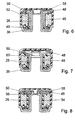
- 6 to 9 is the contact surface 18 formed by a further bearing disc 50.
- This is between a spacer sleeve 52 and an outer rivet edge of the Hollow body 26 held (Fig. 3) or with a separate Rivet 60 connected to the bottom of the hollow body 26, wherein the hollow body 26 as a spacer between the bearing washers 36 and 50 is used (Fig. 6).
- This allows the spacer sleeve 52 omitted.
- the bearing plate 50 on a collar 56 of the hollow body 26 and held by its rivet edge be (Fig. 8 and 9).
- 7 to 9 can both on the spacer sleeve 52 and on the Bearing bush 46 can be dispensed with by using a bearing material 54 applied directly to the hollow body 26, in particular is sprayed on.
- the bearing material 54 is expediently sufficient to the area of the trough 24, so that the bearing washer 36 can be omitted.
- the inner end face of the hollow body 26 expediently closed.
- it can also be designed open (Fig. 6 and 8) if a hat-shaped Part 58 of the sealing cap 48 seals the opening.
- the second lever 62 is covered with a plastic cover 66 disguised. Points the open side of the U-shaped Profile to the plastic cover 66, there is a closed, lever 62 protected on all sides.
- the second lever 62 can take the place of the second lever 12 without restriction, so that one or more advantages can be realized as desired to let.
Landscapes
- Engineering & Computer Science (AREA)
- Mechanical Engineering (AREA)
- General Engineering & Computer Science (AREA)
- Pivots And Pivotal Connections (AREA)
Description
- Fig. 1
- einen Schnitt durch eine Gelenkverbindung nach dem Stand der Technik,
- Fig. 2
- einen Schnitt durch eine erfindungsgemäße Gelenkverbindung,
- Fig. 3
- eine Variante zu Fig. 2 mit einer Lagerbüchse
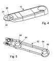
- Fig. 4
- eine perspektivische Ansicht eines ersten Hebels gemäß einer erfindungsgemäßen Gelenkverbindung,
- Fig. 5
- eine perspektivische Ansicht eines zweiten Hebels als Blechbiegeteil,
- Fig. 6-9
- Varianten zu Fig. 2,
- Fig. 10
- einen Schnitt durch eine Gelenkverbindung nach Fig. 1 mit einem zweiten Hebel als Blechbiegeteil und
- Fig. 11
- einen Schnitt durch eine Gelenkverbindung nach Fig. 2 mit einem zweiten Hebel als Blechbiegeteil.
Claims (19)
- Gelenkverbindung mit einem ersten, als Blechbiegeteil gestalteten Hebel (10), der an einem Ende eine Mulde (24) mit einem Lagerbolzen (14) hat, und mit einem zweiten Hebel (12), der ein den Lagerbolzen (14) umfassendes Lagerauge (15) mit einem Lagerteil (16) aufweist, das zwischen zwei an seinen Stirnseiten angeordneten Anlaufflächen (18, 20) gehalten ist, dadurch gekennzeichnet, daß der Lagerbolzen (14) einen Hohlraum (22) hat, der mindestens zu einer Stirnseite hin offen ist.
- Gelenkverbindung nach Anspruch 1 , dadurch gekennzeichnet, daß die Mulde (24) zentral einen tiefgezogenen Hohlkörper (26) aufweist, der in den Hohlraum (22) des Lagerbolzens (14) hineinragt und an seiner Stirnseite (28) mit dem Lagerbolzen (14) vernietet ist.
- Gelenkverbindung nach einem der vorhergehenden Ansprüche, dadurch gekennzeichnet, daß der Hohlraum (22) zur Mulde (24) hin eine Verengung aufweist, die als Anlagefläche (30) für den Hohlkörper (26) dient.
- Gelenkverbindung nach einem der vorhergehenden Ansprüche, dadurch gekennzeichnet, daß der Rand (32) der Mulde (24) nach außen etwa in einem Viertelkreisbogen quer zu einer Schwenkachse ausläuft und radial mit einer Gelenkabdeckung (34) abschließt.
- Gelenkverbindung nach einem der vorhergehenden Ansprüche, dadurch gekennzeichnet, daß in der Mulde (24) eine Lagerscheibe (36) angeordnet ist, an der das Lagerteil (16) anliegt, während die gegenüberliegende Anlauffläche von einem Kragen (38) des Lagerbolzens (14) gebildet wird.
- Gelenkverbindung nach einem der vorhergehenden Ansprüche, dadurch gekennzeichnet, daß zwischen dem Lagerteil (16) und der Lagerscheibe (36) eine Axialdichtung in Form einer Lippendichtung (40) oder eines Profilrings (42, 44) vorgesehen ist.
- Gelenkverbindung nach einem der vorhergehenden Ansprüche, dadurch gekennzeichnet, daß mit dem Lagerteil (16) oder dem Lagerbolzen (14) eine Lagerbuchse (46) aus kunststoffbeschichtetem Stahl verbunden ist.
- Gelenkverbindung nach einem der vorhergehenden Ansprüche, dadurch gekennzeichnet, daß das Lagerteil (14) an seiner der Mulde (24) abgewandten Stirnseite eine Dichtkappe (48) besitzt.
- Gelenkverbindung nach einem der vorhergehenden Ansprüche, dadurch gekennzeichnet, daß der Hohlkörper (26) den Lagerzapfen bildet, indem er durch das Lagerteil (16) hindurchgeführt ist und an seinem äußeren Ende mit einer zweiten Lagerscheibe (50) für das Lagerteil (16) vernietet ist.
- Gelenkverbindung nach Anspruch 9 , dadurch gekennzeichnet, daß als Stützlager für die Lagerscheibe (50) eine Distanzhülse (52) zwischen den beiden Lagerscheiben (36, 50) dient.
- Gelenkverbindung nach Anspruch 9 , dadurch gekennzeichnet, daß der Hohlkörper (26) an seinem äußeren Umfang und die Mulde (24) innen mit einem Lagerwerkstoff (54) beschichtet sind und der Hohlkörper (26) an seinem äußeren Ende einen Bund (56) bildet, auf dem sich die zweite Lagerscheibe (50) abstützt.
- Gelenkverbindung nach einem der vorhergehenden Ansprüche, dadurch gekennzeichnet, daß der Hohlkörper (26) an seinem äußeren Ende geschlossen ist.
- Gelenkverbindung nach Anspruch 1 , dadurch gekennzeichnet, daß der Hohlkörper (26) an seinem äußeren Ende eine Öffnung aufweist, die durch einen zentralen, hutförmigen Teil (58) der Dichtkappe (48) abgedichtet ist.
- Gelenkverbindung nach Anspruch 1 , dadurch gekennzeichnet, daß die zweite Lagerscheibe (50) über den Hohlkörper (26) geführt ist und mit diesem an seiner Stirnseite durch eine Niete (60) verbunden ist.
- Gelenkverbindung nach einem der vorhergehenden Ansprüche oder dem Oberbegriff von Anspruch 1 , dadurch gekennzeichnet, daß der zweite Hebel (62) als Blechbiegeteil mit einem im wesentlichen U-förmigen Profil ausgebildet ist, das im Bereich der Lagerteile (16) tief gezogene Ausstülpungen (64) aufweist, auf die die Lagerteile (16) aufgespritzt sind.
- Gelenkverbindung nach Anspruch 15, dadurch gekennzeichnet, daß das Lagerteil (16) innen und außen der Ausstülpung (64) angeordnet ist.
- Gelenkverbindung nach Anspruch 15 oder 16, dadurch gekennzeichnet, daß das U-förmige Profil von einer Kunststoffabdeckung (66) verkleidet ist.
- Gelenkverbindung nach Anspruch 17, dadurch gekennzeichnet, daß die offene Seite des U-förmigen Profils der Abdekkung (66) zugewandt ist.
- Gelenkverbindung nach Anspruch 18, dadurch gekennzeichnet, daß der Zwischenraum (68) zwischen dem U-förmigen Profil und der Ausstülpung (64) teilweise oder ganz mit Lagerwerkstoff (70) aufgefüllt ist.
Applications Claiming Priority (3)
| Application Number | Priority Date | Filing Date | Title |
|---|---|---|---|
| DE19737070A DE19737070C2 (de) | 1997-08-26 | 1997-08-26 | Gelenkverbindung |
| DE19737070 | 1997-08-26 | ||
| PCT/DE1998/002417 WO1999010210A1 (de) | 1997-08-26 | 1998-08-19 | Gelenkverbindung |
Publications (2)
| Publication Number | Publication Date |
|---|---|
| EP0932534A1 EP0932534A1 (de) | 1999-08-04 |
| EP0932534B1 true EP0932534B1 (de) | 2003-05-28 |
Family
ID=7840176
Family Applications (1)
| Application Number | Title | Priority Date | Filing Date |
|---|---|---|---|
| EP98949918A Expired - Lifetime EP0932534B1 (de) | 1997-08-26 | 1998-08-19 | Gelenkverbindung |
Country Status (6)
| Country | Link |
|---|---|
| US (1) | US6511254B1 (de) |
| EP (1) | EP0932534B1 (de) |
| KR (1) | KR100587202B1 (de) |
| DE (2) | DE19737070C2 (de) |
| ES (1) | ES2201538T3 (de) |
| WO (1) | WO1999010210A1 (de) |
Families Citing this family (7)
| Publication number | Priority date | Publication date | Assignee | Title |
|---|---|---|---|---|
| DE19737070C2 (de) | 1997-08-26 | 2000-11-30 | Bosch Gmbh Robert | Gelenkverbindung |
| DE19910118A1 (de) | 1999-03-08 | 2000-09-14 | Bosch Gmbh Robert | Vorrichtung zum Befestigen eines Wischarms |
| DE10039053A1 (de) * | 2000-08-10 | 2002-02-28 | Bosch Gmbh Robert | Befestigungsteil für einen Scheibenwischer |
| DE10138003A1 (de) * | 2001-08-02 | 2003-02-20 | Bosch Gmbh Robert | Wischerarm sowie Scheibenwischervorrichtung, insbesondere für ein Kraftfahrzeug |
| DE10161976A1 (de) | 2001-12-17 | 2003-06-26 | Bosch Gmbh Robert | Befestigung einer Wischeranlage |
| DE10337753A1 (de) | 2003-08-08 | 2005-03-03 | Robert Bosch Gmbh | Klimaanlage, insbesondere zum Einsatz in Kraftfahrzeugen und Verfahren zu deren Betrieb |
| CN108672749A (zh) * | 2018-06-01 | 2018-10-19 | 宁波爱柯迪精密部件有限公司 | 一种铝压铸成型雨刮臂及其打孔设备 |
Family Cites Families (31)
| Publication number | Priority date | Publication date | Assignee | Title |
|---|---|---|---|---|
| US2229720A (en) * | 1935-10-28 | 1941-01-28 | Productive Inventions Inc | Windshield wiper |
| US2254343A (en) * | 1938-12-05 | 1941-09-02 | Chrysler Corp | Windshield cleaner |
| US2295621A (en) * | 1941-09-25 | 1942-09-15 | Zaiger Max | Windshield wiper arm |
| US2528283A (en) * | 1943-12-10 | 1950-10-31 | Max Zaiger | Blade terminal for windshield wiper arms |
| US2820238A (en) * | 1955-03-23 | 1958-01-21 | Laura E Roth | Wipers for windshields severely curved in part |
| DE2131307A1 (de) * | 1971-06-24 | 1973-01-11 | Bosch Gmbh Robert | Scheibenwischanlage fuer fahrzeuge, insbesondere kraftfahrzeuge |
| US3813726A (en) * | 1972-08-04 | 1974-06-04 | Cons Foods Corp | Vacuum cleaner suction tool with pile agitator rotatable in a horizontal plane for cleaning deep pile shag rugs |
| FR2541641B1 (fr) | 1983-02-25 | 1985-07-19 | Marchal Equip Auto | Systeme d'essuie-glace |
| FR2550287B1 (fr) * | 1983-08-04 | 1986-11-14 | Marchal Equip Auto | Dispositif d'assemblage d'un axe et d'une piece, notamment emboutie, a l'aide d'une rondelle de frettage |
| DE3331311C2 (de) * | 1983-08-31 | 1986-07-17 | Daimler-Benz Ag, 7000 Stuttgart | Wischhebel, insbesondere für Kraftfahrzeuge |
| BE901052A (fr) * | 1984-11-14 | 1985-05-14 | Andre Leroy | Un systeme d'essuie-glace a mecanisme de guidage spatial. |
| US4672709A (en) | 1985-12-19 | 1987-06-16 | General Motors Corporation | Windshield wiper drive |
| FR2599321B1 (fr) * | 1986-06-03 | 1988-09-16 | Champion Spark Plug Europ | Systeme d'essuie-glace pour vehicules a moteur. |
| DE3619048A1 (de) * | 1986-06-06 | 1987-12-10 | Kreuzer Friedhelm Gmbh | Verbindungseinrichtung |
| DE3724777A1 (de) * | 1987-07-25 | 1989-02-09 | Swf Auto Electric Gmbh | Wischarm, insbesondere fuer kraftfahrzeug-scheibenwischeranlagen |
| US4840075A (en) * | 1988-05-20 | 1989-06-20 | Truth Incorporated | Window operator |
| JP2522984Y2 (ja) * | 1990-07-13 | 1997-01-22 | 株式会社三ツ葉電機製作所 | ワイパアームの軸受部構造 |
| AT395963B (de) * | 1991-06-18 | 1993-04-26 | Battlogg Stefan | Scheibenwischeranlage |
| DE4134980B4 (de) * | 1991-10-23 | 2005-12-22 | Itt Automotive Europe Gmbh | Wischvorrichtung für Scheiben von Kraftfahrzeugen |
| DE4309022C2 (de) * | 1993-03-20 | 1995-01-05 | Bilstein August Gmbh Co Kg | Gelenk für Wagenheber |
| DE9306529U1 (de) * | 1993-04-30 | 1994-09-15 | Robert Bosch Gmbh, 70469 Stuttgart | Wischvorrichtung für Scheiben von Kraftfahrzeugen mit einem pendelnd angetriebenen, ein auf der zu wischenden Scheibe angelegtes Wischblatt tragenden Wischerarm |
| FR2705936B1 (fr) * | 1993-06-04 | 1995-08-04 | Valeo Systemes Dessuyage | Dispositif d'essuie-glace comportant une articulation entre une manivelle et une bielle. |
| JP3342779B2 (ja) * | 1994-09-06 | 2002-11-11 | 株式会社ミツバ | ワイパ装置における風受体の取付構造 |
| US5606764A (en) * | 1995-05-17 | 1997-03-04 | Itt Automotive Electrical Systems, Inc. | Windshield wiper system having a wiper blade capable of retraction for hidden park |
| DE19519867A1 (de) * | 1995-05-31 | 1996-12-05 | Teves Gmbh Alfred | Getriebeelement mit Kugelzapfen für in Fahrzeugen verwendete Antriebe, insbesondere für eine Scheibenwischvorrichtung |
| DE19528475A1 (de) * | 1995-08-03 | 1997-02-06 | Teves Gmbh Alfred | Gelenkzapfen für ein Getriebeelement eines in Fahrzeugen verwendbaren Antriebes, insbesondere für eine Scheibenwischvorrichtung |
| DE19639593B4 (de) * | 1996-09-26 | 2010-08-19 | Robert Bosch Gmbh | Wischervorrichtung |
| FR2753942B1 (fr) * | 1996-09-30 | 1998-11-06 | Valeo Systemes Dessuyage | Dispositif d'essuyage d'une vitre de vehicule automobile comportant un dispositif perfectionne d'orientation d'un arbre d'entrainement |
| DE19737070C2 (de) | 1997-08-26 | 2000-11-30 | Bosch Gmbh Robert | Gelenkverbindung |
| US6021539A (en) * | 1997-11-03 | 2000-02-08 | Zhadanov; Eli | Washing device |
| EP0968109B1 (de) * | 1998-01-20 | 2004-08-25 | Robert Bosch Gmbh | Scheibenwischerarm |
-
1997
- 1997-08-26 DE DE19737070A patent/DE19737070C2/de not_active Expired - Fee Related
-
1998
- 1998-08-19 WO PCT/DE1998/002417 patent/WO1999010210A1/de not_active Ceased
- 1998-08-19 KR KR1019997003563A patent/KR100587202B1/ko not_active Expired - Fee Related
- 1998-08-19 ES ES98949918T patent/ES2201538T3/es not_active Expired - Lifetime
- 1998-08-19 DE DE59808527T patent/DE59808527D1/de not_active Expired - Lifetime
- 1998-08-19 EP EP98949918A patent/EP0932534B1/de not_active Expired - Lifetime
- 1998-08-19 US US09/297,100 patent/US6511254B1/en not_active Expired - Lifetime
Also Published As
| Publication number | Publication date |
|---|---|
| EP0932534A1 (de) | 1999-08-04 |
| US6511254B1 (en) | 2003-01-28 |
| DE19737070A1 (de) | 1999-03-11 |
| DE19737070C2 (de) | 2000-11-30 |
| ES2201538T3 (es) | 2004-03-16 |
| WO1999010210A1 (de) | 1999-03-04 |
| DE59808527D1 (de) | 2003-07-03 |
| KR100587202B1 (ko) | 2006-06-08 |
| KR20000068823A (ko) | 2000-11-25 |
Similar Documents
| Publication | Publication Date | Title |
|---|---|---|
| DE60126717T2 (de) | Dichtungsprofil für ein Kraftfahrzeug | |
| EP1181462B1 (de) | Kugelgelenk | |
| DE2516478A1 (de) | Gasfeder | |
| DE10108200A1 (de) | Wischvorrichtung insbesondere für Scheiben von Kraftfahrzeugen | |
| EP0667464B1 (de) | Metallischer, nach Art eines Baukastensystems kombinierbarer Kugelzapfen eines Kugelgelenks | |
| EP2639464A1 (de) | Kugelgelenk mit Balgdichtung | |
| EP0755341A1 (de) | Wischarm, insbesondere für kraftfahrzeuge | |
| EP0487891A1 (de) | Elastisches Gleitlager | |
| DE1906500A1 (de) | Staubabdichtung,insbesondere fuer Kugelgelenkanordnungen | |
| DE1525103A1 (de) | Gestaengeverbindung,vorzugsweise fuer Scheibenwischergestaenge | |
| DE19926955B4 (de) | Stegkappe aus gummielastischem Material | |
| DE2117085A1 (de) | Kugelgelenk zum Kuppeln von Gestängegliedern eines Scheibenwischerantriebs für Fahrzeuge | |
| DE20116358U1 (de) | Kugelgelenk | |
| DE19737070C2 (de) | Gelenkverbindung | |
| EP3592998B1 (de) | Kugelgelenkschutzkappe zum schutz eines fertig montierten kugelgelenks | |
| DE3427778C2 (de) | Schraubensystem umfassend eine Abdrückmutter und Teile des Systems | |
| DE19941820C1 (de) | Sanitärarmatur | |
| DE102009031738A1 (de) | Kugelgelenk | |
| DE10241115B4 (de) | Abdichtungsvorrichtung für Lager | |
| DE4420489C2 (de) | Kugelgelenk | |
| DE4128705A1 (de) | Wischarm fuer scheibenwischer von kraftfahrzeugen | |
| DE19647023A1 (de) | Kugelgelenk für in Fahrzeugen verwendete Antriebe, insbesondere für Scheibenwischervorrichtungen | |
| DE3231638C2 (de) | Scheibenwischerelement mit einem Scheibenwischerarm, der der Wirkung einer Druckfeder unterliegt | |
| EP0717688B1 (de) | Wischarm | |
| DE2949042A1 (de) | Befestigungsanordnung fuer einen fahrzeugrueckblickspiegel |
Legal Events
| Date | Code | Title | Description |
|---|---|---|---|
| PUAI | Public reference made under article 153(3) epc to a published international application that has entered the european phase |
Free format text: ORIGINAL CODE: 0009012 |
|
| AK | Designated contracting states |
Kind code of ref document: A1 Designated state(s): DE ES FR GB IT |
|
| 17P | Request for examination filed |
Effective date: 19990906 |
|
| 17Q | First examination report despatched |
Effective date: 20011108 |
|
| GRAH | Despatch of communication of intention to grant a patent |
Free format text: ORIGINAL CODE: EPIDOS IGRA |
|
| GRAH | Despatch of communication of intention to grant a patent |
Free format text: ORIGINAL CODE: EPIDOS IGRA |
|
| GRAA | (expected) grant |
Free format text: ORIGINAL CODE: 0009210 |
|
| AK | Designated contracting states |
Designated state(s): DE ES FR GB IT |
|
| REG | Reference to a national code |
Ref country code: GB Ref legal event code: FG4D Free format text: NOT ENGLISH |
|
| REF | Corresponds to: |
Ref document number: 59808527 Country of ref document: DE Date of ref document: 20030703 Kind code of ref document: P |
|
| GBT | Gb: translation of ep patent filed (gb section 77(6)(a)/1977) | ||
| ET | Fr: translation filed | ||
| REG | Reference to a national code |
Ref country code: ES Ref legal event code: FG2A Ref document number: 2201538 Country of ref document: ES Kind code of ref document: T3 |
|
| PLBE | No opposition filed within time limit |
Free format text: ORIGINAL CODE: 0009261 |
|
| STAA | Information on the status of an ep patent application or granted ep patent |
Free format text: STATUS: NO OPPOSITION FILED WITHIN TIME LIMIT |
|
| 26N | No opposition filed |
Effective date: 20040302 |
|
| PGFP | Annual fee paid to national office [announced via postgrant information from national office to epo] |
Ref country code: FR Payment date: 20090819 Year of fee payment: 12 Ref country code: ES Payment date: 20090821 Year of fee payment: 12 |
|
| PGFP | Annual fee paid to national office [announced via postgrant information from national office to epo] |
Ref country code: GB Payment date: 20090821 Year of fee payment: 12 |
|
| PGFP | Annual fee paid to national office [announced via postgrant information from national office to epo] |
Ref country code: IT Payment date: 20090824 Year of fee payment: 12 |
|
| GBPC | Gb: european patent ceased through non-payment of renewal fee |
Effective date: 20100819 |
|
| REG | Reference to a national code |
Ref country code: FR Ref legal event code: ST Effective date: 20110502 |
|
| PG25 | Lapsed in a contracting state [announced via postgrant information from national office to epo] |
Ref country code: IT Free format text: LAPSE BECAUSE OF NON-PAYMENT OF DUE FEES Effective date: 20100819 |
|
| PG25 | Lapsed in a contracting state [announced via postgrant information from national office to epo] |
Ref country code: FR Free format text: LAPSE BECAUSE OF NON-PAYMENT OF DUE FEES Effective date: 20100831 |
|
| PG25 | Lapsed in a contracting state [announced via postgrant information from national office to epo] |
Ref country code: GB Free format text: LAPSE BECAUSE OF NON-PAYMENT OF DUE FEES Effective date: 20100819 |
|
| REG | Reference to a national code |
Ref country code: ES Ref legal event code: FD2A Effective date: 20111019 |
|
| PG25 | Lapsed in a contracting state [announced via postgrant information from national office to epo] |
Ref country code: ES Free format text: LAPSE BECAUSE OF NON-PAYMENT OF DUE FEES Effective date: 20100820 |
|
| PGFP | Annual fee paid to national office [announced via postgrant information from national office to epo] |
Ref country code: DE Payment date: 20151022 Year of fee payment: 18 |
|
| REG | Reference to a national code |
Ref country code: DE Ref legal event code: R119 Ref document number: 59808527 Country of ref document: DE |
|
| PG25 | Lapsed in a contracting state [announced via postgrant information from national office to epo] |
Ref country code: DE Free format text: LAPSE BECAUSE OF NON-PAYMENT OF DUE FEES Effective date: 20170301 |