EP0932917B1 - Connecteur electrique pourvu d'un boitier ainsi que d'un contact - Google Patents
Connecteur electrique pourvu d'un boitier ainsi que d'un contact Download PDFInfo
- Publication number
- EP0932917B1 EP0932917B1 EP97942167A EP97942167A EP0932917B1 EP 0932917 B1 EP0932917 B1 EP 0932917B1 EP 97942167 A EP97942167 A EP 97942167A EP 97942167 A EP97942167 A EP 97942167A EP 0932917 B1 EP0932917 B1 EP 0932917B1
- Authority
- EP
- European Patent Office
- Prior art keywords
- contact
- electrical connector
- connector according
- electrical
- chamber
- Prior art date
- Legal status (The legal status is an assumption and is not a legal conclusion. Google has not performed a legal analysis and makes no representation as to the accuracy of the status listed.)
- Expired - Lifetime
Links
Images



Classifications
-
- H—ELECTRICITY
- H01—ELECTRIC ELEMENTS
- H01R—ELECTRICALLY-CONDUCTIVE CONNECTIONS; STRUCTURAL ASSOCIATIONS OF A PLURALITY OF MUTUALLY-INSULATED ELECTRICAL CONNECTING ELEMENTS; COUPLING DEVICES; CURRENT COLLECTORS
- H01R13/00—Details of coupling devices of the kinds covered by groups H01R12/70 or H01R24/00 - H01R33/00
- H01R13/02—Contact members
- H01R13/10—Sockets for co-operation with pins or blades
- H01R13/11—Resilient sockets
- H01R13/113—Resilient sockets co-operating with pins or blades having a rectangular transverse section
-
- H—ELECTRICITY
- H01—ELECTRIC ELEMENTS
- H01R—ELECTRICALLY-CONDUCTIVE CONNECTIONS; STRUCTURAL ASSOCIATIONS OF A PLURALITY OF MUTUALLY-INSULATED ELECTRICAL CONNECTING ELEMENTS; COUPLING DEVICES; CURRENT COLLECTORS
- H01R13/00—Details of coupling devices of the kinds covered by groups H01R12/70 or H01R24/00 - H01R33/00
- H01R13/40—Securing contact members in or to a base or case; Insulating of contact members
- H01R13/42—Securing in a demountable manner
- H01R13/422—Securing in resilient one-piece base or case, e.g. by friction; One-piece base or case formed with resilient locking means
- H01R13/4223—Securing in resilient one-piece base or case, e.g. by friction; One-piece base or case formed with resilient locking means comprising integral flexible contact retaining fingers
-
- H—ELECTRICITY
- H01—ELECTRIC ELEMENTS
- H01R—ELECTRICALLY-CONDUCTIVE CONNECTIONS; STRUCTURAL ASSOCIATIONS OF A PLURALITY OF MUTUALLY-INSULATED ELECTRICAL CONNECTING ELEMENTS; COUPLING DEVICES; CURRENT COLLECTORS
- H01R43/00—Apparatus or processes specially adapted for manufacturing, assembling, maintaining, or repairing of line connectors or current collectors or for joining electric conductors
- H01R43/16—Apparatus or processes specially adapted for manufacturing, assembling, maintaining, or repairing of line connectors or current collectors or for joining electric conductors for manufacturing contact members, e.g. by punching and by bending
Definitions
- the invention relates to an electrical connector having a housing and having at least one electrical contact, the housing having at least one chamber for the electrical contact and the electrical contact having a conductor connection region for connection to an electrical conductor wire and a contact-making region for making contact with a complementary contact pin, the contact-making region being designed in the form of a box with two side walls, a top wall and a bottom wall, the top and bottom wall having a width different from the width of the top wall in the direction perpendicular to the plug-in direction, in such a way, that the side walls run in a manner inclined with respect to the bottom and top walls and with respect to one another.
- US-A-5,281,175 discloses an electrical female contact having the above features.
- the document relates to an electrical female, box-shaped contact with a resilient contact arm in the top wall with a supporting spring and a raised portion on the bottom wall.
- the contact is designed to receive different thicknesses of mating male terminals. It has a vertically extending tab for guidance in a housing. It is designed as a one part contact, may have an insertion funnel and is essentially rectangular in cross-section.
- US-A-3,836,947 also discloses a female electrical contact with a contact-making region with an essentially rectangular cross-section. One side of this region is in the form of a resilient leaf contact spring and a supporting spring overlying the contact spring.
- DE 44 10 951 A1 concerns a flat spring contact, which has a contact-making region in the form of a box in which two contact springs are formed on one side wall, and a supporting spring, which rests on the said contact springs, is an independent part and is connected to the contact-making region by fixing aids. Inwardly embossed contact points are provided on the side opposite to the contact springs.
- US-E-RE-27, 463 discloses a connector block including a conductor according to the preamble of claim 1 for receiving and removably holding an electrical contact in a cavity.
- the cavities are rectangular in cross-section.
- Female contacts having a conductor connection region and a contact-making region are inserted into the cavities.
- the contact-making region of the contacts is essentially box-shaped and has the form of a trapezium in its cross-section perpendicular to the plug-in direction.
- the contacts and the connector block do not seem to have any polarising possibilities.
- the object of the invention is to specify an electrical connector which, given a predetermined width of contact pins or blades and minimum contact pin or blade spacings of a mating connector, nevertheless permits reliable construction of robust chamber walls.
- it is intended to specify an electrical contact which is suitable for such an electrical connector.
- the trapezoidal form at the same time may be used as a polarising possibility.
- the advantage is achieved by providing in cross-section trapezoidal contacts and chambers.
- the electrical contact has a contact spring arm with a supporting spring, the spring properties of the contact spring being optimised thereby. Because of the trapezoidal form of the contact and the fact that the contact spring arm is arranged in the broader top wall, the spring arm may be broad to achieve high contact forces.
- a compensating leaf spring is situated on the side opposite to the contact spring.
- the spring properties of the contact spring arm and compensating leaf spring are co-ordinated with one another in such a way that when a contact pin or contact blade is introduced, initially it is mainly the contact spring arm that is deflected. Only when the thickness of the contact pin or contact blade exceeds a specific thickness the compensating leaf spring is also deflected to a greater extent. The possible deflection of the compensating leaf spring is advantageously limited by stops.
- the compensating leaf spring essentially serves to compensate for tolerances in the thickness of the contact pin or contact blade.
- the compensating leaf spring is substantially more rigid than the contact spring, which has a large elastic region, but less rigid than simple embossed areas or raised portions which are known from the prior art.
- an insertion funnel is formed at the front end of the contact, which funnel serves to simplify the insertion of the contact pin or contact blade.
- This insertion funnel is formed by means of a lug which is bent back from the upper wall of the contact-making region into the interior of the contact-making region. This upper lug can also serve as a stop if the contact spring arm is prestressed.
- the conductor connection region can, for example, be designed as two different crimp regions, one for crimping the conductor wire and one for crimping the insulation of the conductor wire.
- the conductor connection region it is also possible for the conductor connection region to have an insulation-piercing terminal contact, or even to constitute a combination of insulation-piercing terminal contact and crimp contact.
- the electrical contact described can be designed as a one-part contact. This enables particularly cost-effective production.
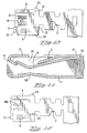
- Figure 1 illustrates a plan view of a contact 1 according to the invention.
- the contact comprises a conductor connection region 2 and a contact-making region 3.
- the conductor connection region 2 serves for connection to an electrical conductor 1 and has two crimp regions, an insulation crimp 21 and a crimp for the electrical conductor wire 22.
- the contact-making region 3 serves to make contact with a complementary contact pin, the contact pin being introduced into the contact-making region from the front end of the latter.
- Figure 2 which illustrates a view from the front end of the contact
- the contact-making region is essentially designed in the form of a box. This box is not rectangular but rather trapezoidal in its cross-section.
- the contact-making region 3 has two side walls 4 and 5, a top wall 6 and a bottom wall 7.
- the bottom wall 7 is in this case designed to be narrower than the top wall 6, thereby achieving the trapezoidal appearance.
- the two side walls 4 and 5 are therefore arranged such that they are inclined with respect to the top wall and with respect to the bottom wall 7, and they also run in a manner inclined with respect to one another.
- Figure 1 permits a view of the top wall 6, it also being possible to see the side walls 4 and 5.
- Figure 2 shows a view of the side wall 5
- Figure 5 shows a view of the side arm wall 4.
- the contact spring arm 8 is illustrated by dashed lines.
- the contact spring has a free end at the front end of the electrical contact 1 and is connected to the top wall 6 in the direction of the conductor connection region 2.
- the top wall comprises two layers 61 and 62 in the region near to the conductor connection region 2.
- the supporting spring arm 9, which is both shown by dashed lines in the illustrations 2 and 5 and can also be seen in Figure 1, is bent away from the upper layer 61.
- the said supporting spring supports the contact spring arm 8, which starts out from the lower layer 62 of the top wall 6.
- the compensating leaf spring 10 can be seen in the figures.
- This is a spring which is cut free at one end and extends away from the conductor connection region. The spring is bent inwards, and two stops 11 and 12 start out from the bottom wall 7 and prevent the spring from overstretching.
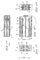
- Figures 6 and 7 illustrate the sections along the section lines B and D through the two crimp regions.
- a lug 13 extends forwards from the top wall 6 and is bent inwards into the contact-making region 3. This lug serves as an insertion funnel for the insertion of a complementary contact pin or contact blade.
- Figure 8 illustrates a section through the electrical contact 1 along the section line BB according to Figure 3.
- the top wall 6 with the two layers 61 and 62 can be seen particularly clearly in this illustration.
- the arrangement of contact spring arm 8 and supporting spring arm 9, as well as compensating leaf spring 10 and stop 12, also becomes clear here.
- the contact spring arm 8 is not prestressed, that is to say the lug 13 serves exclusively for forming an insertion funnel. However, it is possible to achieve prestressing of the contact spring arm 8.
- the lug 13 then likewise serves as a stop for the prestressed contact spring arm 8.
- the section illustrated also shows the opening 25, in which a latching means (illustrated by dashed lines) can engage in order to hold the contact in a chamber.
- the cross-sectionally trapezoidal contact-making region can be seen clearly once again in Figure 9, which illustrates a section along the line AA through Figure 8.
- the side walls 4 and 5 run in a manner inclined with respect to one another.
- the compensating leaf spring 10 is situated above the stops 11 and 12 inside the contact-making region.
- the contact spring arm 8 is supported by the supporting spring arm 9.
- the contact spring arm 8 is bent in the contact-making region, as illustrated in Figure 9. This bending extends over the entire length of the contact spring arm 8 in order to increase the stiffness.
- the layout of the contact according to the invention can be seen clearly in Figure 10.
- the contact-making region 3 is formed by folding a number of times, the top wall being formed from two layers 61 and 62.
- the contact spring arm 8 is formed from the layer 61, while the supporting spring arm 9 and the lug 13 are formed from the layer 62.
- the stops 11 and 12 as well as the compensating leaf spring 10 are formed from the bottom wall 7.
- An opening 23 and a corresponding lug-24, which secures the lower layer of the wall 61 to the side wall, can be seen from the layout.
- the cross-hatched regions on the contact spring arm 8 and the compensating leaf spring 10 represent those regions of the contact which are gold-plated for the purpose of better contact-making.
- Figure 11 illustrates a longitudinal section (as in Figure 8) through a further version of a contact and Figure 12 illustrates a corresponding layout. These differ from the contact illustrated in Figures 8 and 10 in terms of the different compensating spring.
- the compensating leaf spring 100 illustrated is joined at both ends and cut free only on the sides. Its deflection is thereby limited and stops are not provided.
- FIGS 13 to 18 then illustrate a housing which is suitable for accommodating a contact according to the invention.
- the housing 14 has four contact chambers 17 to 20.
- the contact chambers each extend from the cable end of the housing 14 as far as the plug-in face end of the housing, where openings are provided for the introduction of complementary contact pins.
- the chamber walls between the individual chambers 17 to 20 are very thin.
- the width of the chamber walls namely their trapezoidal cross-section, it is possible for the width of the chamber walls to change over the layer thereof and, as a result, for a robust region to be produced at least on one side. This enables the contacts, or the contact chambers, to be arranged as close to one another as possible.
- each contact chamber is assigned a flexible arm 15 having a latching lug 16 which engages in the contact chamber.
- the latching lug 16 enters an opening 25 in the top wall 6 of the contact (see Figure 1 or 8) and secures the contact in the chamber.
- the flexible arm 15 is illustrated once again, in detail, in Figure 18. It can be seen here that the end face 26 of the flexible arm is bevelled. This bevelling serves the following purpose: if a contact is introduced incompletely into the contact chamber, the flexible contact arm 15 is bent outwards, that is to say out of the contact chamber. If an attempt is made in this state to connect a complementary connector to the illustrated connector, then a wall region of the complementary connector, which normally engages in the depression 27 (see Figure 13), runs up against the oblique end face 26 of the flexible arm. The special configuration of the end face prevents the flexible arm from being pressed back into its original position by the wall region of the complementary connector even though the contact is incorrectly introduced. What is effected by this is that the flexible arm 15 is moved even further out of the chamber.
Landscapes
- Coupling Device And Connection With Printed Circuit (AREA)
- Connector Housings Or Holding Contact Members (AREA)
Abstract
Claims (19)
- Connecteur électrique comprenant un boítier et au moins un contact électrique, le boítier (14) comportant au moins une chambre (17-20) destinée à recevoir le contact électrique, le contact électrique (1) comportant une région de connexion d'un conducteur (2) en vue de la connexion à un fil conducteur électrique, et une région d'établissement d'un contact (3) pour établir un contact avec une broche de contact ou une lame de contact complémentaire, la région d'établissement du contact (3) étant conçue sous forme d'une boíte, avec deux parois latérales (4, 5), une paroi supérieure (6) et une paroi inférieure (7), la paroi inférieure (7) ayant une largeur différente de la largeur de la paroi supérieure (6) dans la direction perpendiculaire à la direction d'enfichage, de sorte que les parois latérales (4, 5) sont inclinées par rapport aux parois inférieures et supérieures (6, 7) et l'une par rapport à l'autre, caractérisé en ce qu'au moins une chambre (17-20) a une section transversale trapézoïdale.
- Connecteur électrique selon la revendication 1, les chambres ayant une section transversale de forme trapézoïdale, symétrique à sa hauteur.
- Connecteur électrique selon les revendications 1 ou 2, caractérisé en ce que les parois des chambres entre les chambres adjacentes (17, 19) d'une rangée à configuration alignée des contacts ont une section transversale plus large sur un côté que sur l'autre côté.
- Connecteur électrique selon l'une des revendications 1 ou 3, caractérisé en ce que chaque chambre de contact (17-20) comporte un bras flexible (15), débordant par l'intermédiaire d'une languette de verrouillage (16) dans la chambre, de sorte à fixer le contact électrique dans la chambre (17-20).
- Connecteur électrique selon la revendication 4, caractérisé en ce que la face d'extrémité (26) du bras flexible (15) fait face à la face avant du connecteur et est chanfreinée, de sorte que lorsque le bras flexible (15) est plié vers l'extérieur, en-dehors de la chambre de contact (17), une force étant appliquée à la face d'extrémité (26), dans la direction d'accouplement, une force est appliquée au bras flexible (15) orientée dans la direction l'écartant de ladite chambre du contact (17).
- Connecteur électrique selon la revendication 1, caractérisé en ce que la région d'établissement d'un contact (3) du contact (1) comporte au moins un bras élastique de contact (8) s'étendant à l'écart de la région de connexion du conducteur (2), la région d'établissement du contact (3) comportant un bras élastique de support (9) s'étendant à l'écart de la région de connexion du conducteur (2) et reposant à l'extérieur sur le bras élastique de contact (8).
- Connecteur électrique selon la revendication 6, caractérisé en ce qu'un ressort à lames de compensation (10, 100) est agencé dans la région d'établissement du contact (3), sur le côté opposé au bras élastique de contact (8).
- Connecteur électrique selon les revendications 6 ou 7, caractérisé en ce que la région d'établissement d'un contact (3) du contact (1) a une section transversale en forme de trapèze, perpendiculaire à la direction d'enfichage.
- Connecteur électrique selon la revendication 8, caractérisé en ce que la région d'établissement du contact (1) a une section transversale en forme de trapèze symétrique à sa hauteur.
- Connecteur électrique selon la revendication 8, caractérisé en ce que le ressort de support (9) repose à l'extérieur sur le ressort de contact (8).
- Connecteur électrique selon l'une des revendications 6 ou 10, caractérisé en ce que des butoirs (11, 12) sont agencés dans le contact (1) pour limiter la flexion maximale du ressort à lames de compensation (10).
- Connecteur électrique selon l'une des revendications 6 à 11, caractérisé en ce que le contact (1) est composé d'une seule pièce.
- Connecteur électrique selon l'une des revendications 6 à 12, caractérisé en ce que la paroi supérieure (6) de la région d'établissement d'un contact (3) du contact (1) est en partie composée de deux couches, le bras élastique de contact (8) étant formé à partir de la couche interne et le bras élastique de support (9) étant formé à partir de la couche externe.
- Connecteur électrique selon l'une des revendications 6 à 13, caractérisé en ce qu'une languette (13) est pliée vers l'arrière dans l'ouverture de contact au niveau de l'extrémité avant du contact (1), à partir de la couche supérieure de la paroi supérieure (6) du contact électrique (1) .
- Connecteur électrique selon l'une des revendications 6 à 14, caractérisé en ce que le ressort à lames de compensation (10) est relié au niveau d'un côté à la région de connexion du conducteur (2) et comporte une extrémité libre au niveau du côté opposé.
- Connecteur électrique selon l'une des revendications 6 à 14, caractérisé en ce que le ressort à lames de compensation (100) constitue un pont, dégagé au niveau des côtés et plié dans la région d'établissement du contact (3).
- Connecteur électrique selon l'une des revendications 6 à 16, caractérisé en ce qu'un entonnoir d'insertion est formé au niveau de l'extrémité avant du contact.
- Connecteur électrique selon l'une des revendications 6 à 17, caractérisé en ce que le bras élastique de contact (8) est soumis à une précontrainte.
- Connecteur électrique selon l'une des revendications 6 à 18. caractérisé en ce qu'une ouverture (25) est agencée dans la paroi supérieure (6) du contact électrique (1), en vue de recevoir un moyen destiné à verrouiller le contact dans une chambre d'un boítier.
Priority Applications (1)
| Application Number | Priority Date | Filing Date | Title |
|---|---|---|---|
| EP97942167A EP0932917B1 (fr) | 1996-10-17 | 1997-10-16 | Connecteur electrique pourvu d'un boitier ainsi que d'un contact |
Applications Claiming Priority (4)
| Application Number | Priority Date | Filing Date | Title |
|---|---|---|---|
| EP96116685 | 1996-10-17 | ||
| EP96116685 | 1996-10-17 | ||
| PCT/IB1997/001284 WO1998018181A1 (fr) | 1996-10-17 | 1997-10-16 | Connecteur electrique pourvu d'un boitier ainsi que d'un contact electrique et contact electrique |
| EP97942167A EP0932917B1 (fr) | 1996-10-17 | 1997-10-16 | Connecteur electrique pourvu d'un boitier ainsi que d'un contact |
Publications (2)
| Publication Number | Publication Date |
|---|---|
| EP0932917A1 EP0932917A1 (fr) | 1999-08-04 |
| EP0932917B1 true EP0932917B1 (fr) | 2000-05-24 |
Family
ID=8223308
Family Applications (1)
| Application Number | Title | Priority Date | Filing Date |
|---|---|---|---|
| EP97942167A Expired - Lifetime EP0932917B1 (fr) | 1996-10-17 | 1997-10-16 | Connecteur electrique pourvu d'un boitier ainsi que d'un contact |
Country Status (6)
| Country | Link |
|---|---|
| US (1) | US6305992B1 (fr) |
| EP (1) | EP0932917B1 (fr) |
| JP (1) | JP2001506048A (fr) |
| AU (1) | AU4394997A (fr) |
| DE (1) | DE69702142T2 (fr) |
| WO (1) | WO1998018181A1 (fr) |
Cited By (3)
| Publication number | Priority date | Publication date | Assignee | Title |
|---|---|---|---|---|
| EP1724878A3 (fr) * | 2005-05-19 | 2007-01-03 | Deutsch Engineered Connecting Devices | Contact à douille sans manchon estampé et formé |
| CN110649410A (zh) * | 2018-06-26 | 2020-01-03 | 矢崎总业株式会社 | 端子金属配件 |
| KR102878494B1 (ko) * | 2024-07-11 | 2025-10-31 | (주)우주일렉트로닉스 | 고탄력 접속 구조를 갖는 터미널 |
Families Citing this family (39)
| Publication number | Priority date | Publication date | Assignee | Title |
|---|---|---|---|---|
| JP3224369B2 (ja) * | 1998-07-16 | 2001-10-29 | 日本圧着端子製造株式会社 | コネクタの端子及びハウジング |
| JP4600874B2 (ja) * | 1998-09-11 | 2010-12-22 | 日本圧着端子製造株式会社 | コネクタの端子及びコネクタ |
| AU5157800A (en) * | 1999-05-28 | 2000-12-18 | Whitaker Corporation, The | Electrical contact receptacle terminal to mate with round and rectangular pins |
| DE10161514B4 (de) * | 2000-12-18 | 2007-04-12 | Sumitomo Wiring Systems, Ltd., Yokkaichi | Anschlussbuchse |
| DE10119642A1 (de) * | 2001-04-20 | 2002-11-14 | Lenze Gmbh & Co Kg Aerzen | Stator für eine elektrische Drehfeldmaschine, insbesondere Synchronmaschine |
| JP3415133B1 (ja) * | 2002-06-06 | 2003-06-09 | 住友電装株式会社 | 端子金具及びコネクタ |
| FR2848346B1 (fr) * | 2002-12-05 | 2005-02-11 | Gemplus Card Int | Adaptateur pour la connexion electrique d'une mini-carte a circuits(s)integre(s)dans un connecteur pour carte a memoire |
| BRPI0411373A (pt) * | 2003-06-18 | 2006-08-01 | Ryosei Electro Circuit Sys Ltd | terminal de conexão |
| JP3976008B2 (ja) * | 2004-01-07 | 2007-09-12 | 住友電装株式会社 | 端子金具 |
| JP4514645B2 (ja) * | 2004-07-12 | 2010-07-28 | タイコエレクトロニクスジャパン合同会社 | 雌型端子 |
| JP4385923B2 (ja) * | 2004-09-29 | 2009-12-16 | 住友電装株式会社 | 端子金具及びこれを用いたコネクタ |
| EP1643599B1 (fr) * | 2004-09-29 | 2008-12-17 | Sumitomo Wiring Systems, Ltd. | Organe de contact et connecteur avec un tel organe de contact |
| KR101121255B1 (ko) * | 2005-02-09 | 2012-03-23 | 에프씨아이 오토모티브 홀딩 | 탄성 접촉 플레이트를 포함하는 암형 전기 접촉부 |
| JP4482823B2 (ja) * | 2005-12-26 | 2010-06-16 | 住友電装株式会社 | 端子金具 |
| JP2009245655A (ja) * | 2008-03-28 | 2009-10-22 | Yazaki Corp | 雌端子構造及びその連鎖端子 |
| TWI431857B (zh) * | 2008-10-31 | 2014-03-21 | Bellwether Electronic Corp | A method of manufacturing a conductive terminal, and an electronic card connector including the conductive terminal |
| JP5723133B2 (ja) * | 2010-10-12 | 2015-05-27 | 矢崎総業株式会社 | 雌型端子金具 |
| US8596881B2 (en) | 2010-12-09 | 2013-12-03 | Microsoft Corporation | Power and data connector |
| JP5729234B2 (ja) * | 2011-09-21 | 2015-06-03 | 住友電装株式会社 | 端子金具 |
| JP2013069496A (ja) * | 2011-09-21 | 2013-04-18 | Sumitomo Wiring Syst Ltd | 端子金具 |
| JP5754413B2 (ja) * | 2012-04-26 | 2015-07-29 | 住友電装株式会社 | 端子金具 |
| JP6124537B2 (ja) * | 2012-09-03 | 2017-05-10 | 矢崎総業株式会社 | メス端子 |
| DE102012215780B4 (de) * | 2012-09-06 | 2024-06-27 | Robert Bosch Gmbh | Formstabiler Kontakt, hergestellt mittels Tiefziehverfahren |
| NO2738575T3 (fr) | 2012-11-28 | 2018-04-07 | ||
| JP2014160545A (ja) * | 2013-02-19 | 2014-09-04 | Sumitomo Wiring Syst Ltd | 雌端子金具 |
| JP2014170709A (ja) * | 2013-03-05 | 2014-09-18 | Sumitomo Wiring Syst Ltd | 雌端子金具 |
| EP3005485B1 (fr) | 2013-06-07 | 2018-01-03 | FCI Asia Pte. Ltd. | Connecteur pour cable |
| US9972932B2 (en) * | 2013-08-19 | 2018-05-15 | Fci Americas Technology Llc | Electrical connector with high retention force |
| US10230189B2 (en) | 2013-12-03 | 2019-03-12 | Amphenol Fci Asia Pte Ltd | Connector and pin receiving contact for such a connector |
| US10126801B2 (en) | 2016-03-31 | 2018-11-13 | Navid Zarkani | Computer power conditioning system |
| JP2017220416A (ja) * | 2016-06-10 | 2017-12-14 | 住友電装株式会社 | 端子金具 |
| CN107181082A (zh) * | 2017-06-20 | 2017-09-19 | 厦门广泓工贸有限公司 | 一种连料式电连接器及其应用的led灯泡 |
| CN115986449A (zh) | 2018-03-16 | 2023-04-18 | 富加宜(美国)有限责任公司 | 高密度电连接器 |
| JP2020102338A (ja) * | 2018-12-21 | 2020-07-02 | タイコエレクトロニクスジャパン合同会社 | コネクタハウジングおよびコネクタ |
| KR102222698B1 (ko) * | 2019-05-31 | 2021-03-04 | 히로세코리아 주식회사 | 보드 투 와이어 커넥터 |
| JP7165306B2 (ja) | 2019-06-11 | 2022-11-04 | 株式会社オートネットワーク技術研究所 | 端子、及び、端子付き電線 |
| KR102446801B1 (ko) * | 2019-12-24 | 2022-09-26 | 주식회사 유라 | 암단자 |
| JP7396188B2 (ja) * | 2020-04-30 | 2023-12-12 | 住友電装株式会社 | 雌端子金具 |
| CN117855906B (zh) * | 2022-09-30 | 2025-04-08 | 比亚迪股份有限公司 | 端子、电连接器、线束和车辆 |
Family Cites Families (11)
| Publication number | Priority date | Publication date | Assignee | Title |
|---|---|---|---|---|
| USRE27463E (en) * | 1971-02-23 | 1972-08-15 | Connector block | |
| US3781760A (en) | 1972-03-28 | 1973-12-25 | Du Pont | Connector block |
| US3836947A (en) | 1973-02-23 | 1974-09-17 | Amp Inc | Electrical contact receptacle with helper spring |
| JPS54102590A (en) | 1978-01-31 | 1979-08-13 | Yazaki Corp | Electric connector |
| JPH0548271A (ja) * | 1991-08-12 | 1993-02-26 | Murata Mfg Co Ltd | 機能性多層回路基板 |
| DE9211819U1 (de) * | 1992-07-07 | 1993-11-04 | Grote & Hartmann | Elektrisches Kontaktelement |
| DE4227287A1 (de) * | 1992-08-18 | 1994-02-24 | Framatome Connectors Int | Elektrischer Federkontakt |
| US5281175A (en) * | 1993-03-30 | 1994-01-25 | General Motors Corporation | Female electrical terminal |
| DE9308142U1 (de) * | 1993-05-27 | 1994-10-13 | Siemens Ag | Flachfederkontakt für eine Steckverbindung |
| GB9315160D0 (en) * | 1993-07-22 | 1993-09-08 | Amp Gmbh | Electrical terminal for use with short circuit spring contacts |
| JP3533536B2 (ja) * | 1994-07-11 | 2004-05-31 | 住友電装株式会社 | 雌端子金具 |
-
1997
- 1997-10-16 EP EP97942167A patent/EP0932917B1/fr not_active Expired - Lifetime
- 1997-10-16 AU AU43949/97A patent/AU4394997A/en not_active Abandoned
- 1997-10-16 US US09/077,814 patent/US6305992B1/en not_active Expired - Lifetime
- 1997-10-16 DE DE69702142T patent/DE69702142T2/de not_active Expired - Lifetime
- 1997-10-16 WO PCT/IB1997/001284 patent/WO1998018181A1/fr not_active Ceased
- 1997-10-16 JP JP51916098A patent/JP2001506048A/ja active Pending
Cited By (4)
| Publication number | Priority date | Publication date | Assignee | Title |
|---|---|---|---|---|
| EP1724878A3 (fr) * | 2005-05-19 | 2007-01-03 | Deutsch Engineered Connecting Devices | Contact à douille sans manchon estampé et formé |
| CN110649410A (zh) * | 2018-06-26 | 2020-01-03 | 矢崎总业株式会社 | 端子金属配件 |
| EP3588687B1 (fr) * | 2018-06-26 | 2021-11-03 | Yazaki Corporation | Raccord métallique de borne |
| KR102878494B1 (ko) * | 2024-07-11 | 2025-10-31 | (주)우주일렉트로닉스 | 고탄력 접속 구조를 갖는 터미널 |
Also Published As
| Publication number | Publication date |
|---|---|
| EP0932917A1 (fr) | 1999-08-04 |
| JP2001506048A (ja) | 2001-05-08 |
| DE69702142D1 (de) | 2000-06-29 |
| AU4394997A (en) | 1998-05-15 |
| WO1998018181A1 (fr) | 1998-04-30 |
| US6305992B1 (en) | 2001-10-23 |
| DE69702142T2 (de) | 2001-02-01 |
Similar Documents
| Publication | Publication Date | Title |
|---|---|---|
| US6305992B1 (en) | Electrical connector having a housing and an electrical contact and electrical contact | |
| US6475040B1 (en) | Electrical contact receptacle to mate with round and rectangular pins | |
| US5938485A (en) | Electrical terminal | |
| EP0517077B1 (fr) | Contact électrique | |
| EP0389955B1 (fr) | Connecteur pour verrouiller doublement un terminal électrique | |
| JP4372138B2 (ja) | 電気接点 | |
| JP4650918B2 (ja) | 電気コネクタ | |
| US6375502B2 (en) | Connector | |
| KR100279193B1 (ko) | 고접촉력핀수용전기단자 | |
| US6217379B1 (en) | Plug-in contact | |
| JP3497615B2 (ja) | 雌型端子 | |
| JPH05258792A (ja) | 過度応力防止手段を有する雄電気端子 | |
| US5611716A (en) | Electrical contact having improved secondary locking surfaces | |
| US6921289B2 (en) | Joint connector and its terminals | |
| JP3304686B2 (ja) | 相互接続用端子 | |
| JP3304690B2 (ja) | 相互接続用端子及びジョイントコネクタ | |
| US20020055297A1 (en) | Modular female electrical terminal | |
| EP0979543B1 (fr) | Contact electrique | |
| EP0958638B1 (fr) | Borne electrique polarisee d'une seule piece | |
| JPH11144789A (ja) | 端子構造 | |
| EP0736930A1 (fr) | Contact avec barre de contact à l'intérieur qui est supporté indépendamment | |
| EP1199773B1 (fr) | Connecteur électrique et borne | |
| JP3147783B2 (ja) | 雌側端子金具 | |
| EP1439611B1 (fr) | Connecteur pour câble plat | |
| US6048231A (en) | Bulb socket plug and method of producing same |
Legal Events
| Date | Code | Title | Description |
|---|---|---|---|
| PUAI | Public reference made under article 153(3) epc to a published international application that has entered the european phase |
Free format text: ORIGINAL CODE: 0009012 |
|
| 17P | Request for examination filed |
Effective date: 19990408 |
|
| AK | Designated contracting states |
Kind code of ref document: A1 Designated state(s): DE ES FR GB IT |
|
| GRAG | Despatch of communication of intention to grant |
Free format text: ORIGINAL CODE: EPIDOS AGRA |
|
| RTI1 | Title (correction) |
Free format text: ELECTRICAL CONNECTOR HAVING A HOUSING AND AN ELECTRICAL CONTACT |
|
| 17Q | First examination report despatched |
Effective date: 19990929 |
|
| GRAG | Despatch of communication of intention to grant |
Free format text: ORIGINAL CODE: EPIDOS AGRA |
|
| GRAH | Despatch of communication of intention to grant a patent |
Free format text: ORIGINAL CODE: EPIDOS IGRA |
|
| GRAH | Despatch of communication of intention to grant a patent |
Free format text: ORIGINAL CODE: EPIDOS IGRA |
|
| GRAA | (expected) grant |
Free format text: ORIGINAL CODE: 0009210 |
|
| AK | Designated contracting states |
Kind code of ref document: B1 Designated state(s): DE ES FR GB IT |
|
| PG25 | Lapsed in a contracting state [announced via postgrant information from national office to epo] |
Ref country code: IT Free format text: LAPSE BECAUSE OF FAILURE TO SUBMIT A TRANSLATION OF THE DESCRIPTION OR TO PAY THE FEE WITHIN THE PRESCRIBED TIME-LIMIT;WARNING: LAPSES OF ITALIAN PATENTS WITH EFFECTIVE DATE BEFORE 2007 MAY HAVE OCCURRED AT ANY TIME BEFORE 2007. THE CORRECT EFFECTIVE DATE MAY BE DIFFERENT FROM THE ONE RECORDED. Effective date: 20000524 Ref country code: ES Free format text: THE PATENT HAS BEEN ANNULLED BY A DECISION OF A NATIONAL AUTHORITY Effective date: 20000524 |
|
| REF | Corresponds to: |
Ref document number: 69702142 Country of ref document: DE Date of ref document: 20000629 |
|
| ET | Fr: translation filed | ||
| PLBE | No opposition filed within time limit |
Free format text: ORIGINAL CODE: 0009261 |
|
| STAA | Information on the status of an ep patent application or granted ep patent |
Free format text: STATUS: NO OPPOSITION FILED WITHIN TIME LIMIT |
|
| 26N | No opposition filed | ||
| REG | Reference to a national code |
Ref country code: GB Ref legal event code: IF02 |
|
| PGFP | Annual fee paid to national office [announced via postgrant information from national office to epo] |
Ref country code: GB Payment date: 20061025 Year of fee payment: 10 |
|
| GBPC | Gb: european patent ceased through non-payment of renewal fee |
Effective date: 20071016 |
|
| REG | Reference to a national code |
Ref country code: FR Ref legal event code: ST Effective date: 20080630 |
|
| PGFP | Annual fee paid to national office [announced via postgrant information from national office to epo] |
Ref country code: FR Payment date: 20061017 Year of fee payment: 10 |
|
| PG25 | Lapsed in a contracting state [announced via postgrant information from national office to epo] |
Ref country code: GB Free format text: LAPSE BECAUSE OF NON-PAYMENT OF DUE FEES Effective date: 20071016 |
|
| PG25 | Lapsed in a contracting state [announced via postgrant information from national office to epo] |
Ref country code: FR Free format text: LAPSE BECAUSE OF NON-PAYMENT OF DUE FEES Effective date: 20071031 |
|
| PGFP | Annual fee paid to national office [announced via postgrant information from national office to epo] |
Ref country code: DE Payment date: 20161027 Year of fee payment: 20 |
|
| REG | Reference to a national code |
Ref country code: DE Ref legal event code: R071 Ref document number: 69702142 Country of ref document: DE |