EP0933192A1 - Cartons et cloisons - Google Patents
Cartons et cloisons Download PDFInfo
- Publication number
- EP0933192A1 EP0933192A1 EP98300601A EP98300601A EP0933192A1 EP 0933192 A1 EP0933192 A1 EP 0933192A1 EP 98300601 A EP98300601 A EP 98300601A EP 98300601 A EP98300601 A EP 98300601A EP 0933192 A1 EP0933192 A1 EP 0933192A1
- Authority
- EP
- European Patent Office
- Prior art keywords
- blank
- divisions
- secured
- case
- panels
- Prior art date
- Legal status (The legal status is an assumption and is not a legal conclusion. Google has not performed a legal analysis and makes no representation as to the accuracy of the status listed.)
- Withdrawn
Links
- 239000000853 adhesive Substances 0.000 claims abstract description 15
- 230000001070 adhesive effect Effects 0.000 claims abstract description 15
- 238000000034 method Methods 0.000 claims abstract description 15
- 239000000463 material Substances 0.000 claims abstract description 14
- 239000004831 Hot glue Substances 0.000 claims abstract description 7
- 238000004519 manufacturing process Methods 0.000 claims abstract description 7
- 241001170716 Garra gotyla Species 0.000 description 12
- 239000003292 glue Substances 0.000 description 6
- 230000032823 cell division Effects 0.000 description 2
- 238000003780 insertion Methods 0.000 description 2
- 230000037431 insertion Effects 0.000 description 2
- 239000004821 Contact adhesive Substances 0.000 description 1
- 238000010276 construction Methods 0.000 description 1
- 230000005484 gravity Effects 0.000 description 1
- 230000000717 retained effect Effects 0.000 description 1
- 239000011090 solid board Substances 0.000 description 1
- 230000002459 sustained effect Effects 0.000 description 1
Images


Classifications
-
- B—PERFORMING OPERATIONS; TRANSPORTING
- B65—CONVEYING; PACKING; STORING; HANDLING THIN OR FILAMENTARY MATERIAL
- B65D—CONTAINERS FOR STORAGE OR TRANSPORT OF ARTICLES OR MATERIALS, e.g. BAGS, BARRELS, BOTTLES, BOXES, CANS, CARTONS, CRATES, DRUMS, JARS, TANKS, HOPPERS, FORWARDING CONTAINERS; ACCESSORIES, CLOSURES, OR FITTINGS THEREFOR; PACKAGING ELEMENTS; PACKAGES
- B65D5/00—Rigid or semi-rigid containers of polygonal cross-section, e.g. boxes, cartons or trays, formed by folding or erecting one or more blanks made of paper
- B65D5/42—Details of containers or of foldable or erectable container blanks
- B65D5/44—Integral, inserted or attached portions forming internal or external fittings
- B65D5/48—Partitions
- B65D5/48024—Partitions inserted
- B65D5/48026—Squaring or like elements, e.g. honeycomb element, i.e. at least four not aligned compartments
-
- B—PERFORMING OPERATIONS; TRANSPORTING
- B31—MAKING ARTICLES OF PAPER, CARDBOARD OR MATERIAL WORKED IN A MANNER ANALOGOUS TO PAPER; WORKING PAPER, CARDBOARD OR MATERIAL WORKED IN A MANNER ANALOGOUS TO PAPER
- B31B—MAKING CONTAINERS OF PAPER, CARDBOARD OR MATERIAL WORKED IN A MANNER ANALOGOUS TO PAPER
- B31B50/00—Making rigid or semi-rigid containers, e.g. boxes or cartons
- B31B50/74—Auxiliary operations
- B31B50/81—Forming or attaching accessories, e.g. opening devices, closures or tear strings
-
- B—PERFORMING OPERATIONS; TRANSPORTING
- B31—MAKING ARTICLES OF PAPER, CARDBOARD OR MATERIAL WORKED IN A MANNER ANALOGOUS TO PAPER; WORKING PAPER, CARDBOARD OR MATERIAL WORKED IN A MANNER ANALOGOUS TO PAPER
- B31B—MAKING CONTAINERS OF PAPER, CARDBOARD OR MATERIAL WORKED IN A MANNER ANALOGOUS TO PAPER
- B31B2105/00—Rigid or semi-rigid containers made by assembling separate sheets, blanks or webs
-
- B—PERFORMING OPERATIONS; TRANSPORTING
- B31—MAKING ARTICLES OF PAPER, CARDBOARD OR MATERIAL WORKED IN A MANNER ANALOGOUS TO PAPER; WORKING PAPER, CARDBOARD OR MATERIAL WORKED IN A MANNER ANALOGOUS TO PAPER
- B31B—MAKING CONTAINERS OF PAPER, CARDBOARD OR MATERIAL WORKED IN A MANNER ANALOGOUS TO PAPER
- B31B2120/00—Construction of rigid or semi-rigid containers
- B31B2120/20—Construction of rigid or semi-rigid containers provided with two or more compartments
Definitions
- This invention relates to the manufacture of cartons, cases or the like (hereafter called "cases") in which are secured divisions subdividing the available space into a number of cells for receiving individual items such as bottles. It also relates to cases with such secured divisions themselves.
- erection of the sleeve at the filling line may be arranged to cause erection of the divisions.
- the glued joint ensures that the divisions are properly retained within the flattened sleeve during transport. It also ensures that the divisions are maintained in the proper position in the erected case on the filling line. This is particularly important with 1x2, 2x2 and 2x3 cell divisions, which are not inherently stable in the case. Such divisions cannot readily be used on automatic filling lines without being fixed in the case.
- the present invention provides a process for the manufacture of cartons, cases or the like comprising the steps of:
- the divisions are secured to the blank in a flattened state, and the folded blank is flat, for convenience in handling and transport.
- the folding step may bring opposed edges of the blank together, these edges subsequently being secured to one another to form a sleeve surrounding the divisions.
- the divisions are secured to the blank by a quick setting adhesive such as a hot melt adhesive.
- a quick setting adhesive such as a hot melt adhesive.
- the invention also provides apparatus for automatically carrying out the above process steps.
- the invention correspondingly provides, in a fully or partly erected state, a case formed from a blank of sheet material having divisions secured therein, characterised in that the divisions are secured in the case by a quick setting adhesive such as a hot melt adhesive.
- One end of at least one sheet of material comprising the division may be secured to the blank; an opposite end or ends of the division sheet or sheets terminating short of a wall of the erected case, to economise on material.
- At least two different sheets of material comprising the divisions are secured to the blank, whereby erection of the blank from a flattened state may be arranged to cause the divisions to be erected from a flattened state.
- the blank may be divided into panels by hinge lines, said two sheets being secured to the same panel or to different panels, for example adjacent panels.
- the blank includes opposed edges brought together and secured to one another to form a sleeve, these edges being on different panels to the one(s) to which the division is secured.
- the division may thus be placed on a central region of the open blank and the opposed edge bearing panels brought together and secured over the divisions to form the sleeve enclosing the divisions.
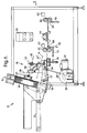
- the case forming apparatus 10 shown in figure 1 comprises an infeed belt conveyor 12 onto which batches of flat case blanks 14 are placed on end, to be carried into a feed hopper 16.
- the blanks 14 may be formed by any conventional means, for example die cutting.
- a pick-and-place mechanism 18 comprising a sucker head 20.
- Individual blanks 14 are pulled past spring fingers or other retaining means at the feed hopper mouth, the sucker head 20 being pivotably carried at the end of a swing arm 22 actuated by a motor 24, crank 26 and connecting rod 28.
- a guide rod indicated by line 30 is rigidly mounted to the sucker head 20 and slides in a linear bearing 32 itself rotatably mounted to the apparatus frame.
- the sucker head and the blank which it carries therefore rotate to the horizontal position indicated at 20'.
- the blank is then released by the sucker head 20 to lie on a horizontal table indicated at 34 and the sucker head 20 and swing arm 22 move back towards the hopper 16 to pick and place the next blank 14.
- Edges of the blank 14 on the table 34 are engaged by two sets of fingers 36 (only one set visible in figure 1) movable towards and away from each other perpendicularly to the plane of figure 1, i.e. in the y direction in figure 3, to centralise the blank at a datum position in the y direction.
- a pusher 38 then moves the blank 14 into the nip of a set of feed rollers 40 which carry it past glue heads 42 which apply hot melt adhesive at the hatched areas 44 shown in figure 3.
- a stop 46 is placed to intercept the blank as it leaves the rollers 40.
- a positioning finger 48 is moved upwardly behind the blank 14 by an actuator 50 and then forwardly in the x direction (figure 3) by an actuator 52 to push the blank 14 against the stop 46. In this way the blank is accurately positioned in the x and y directions for placement of the divisions.
- a feed mechanism 54 for divisions 56 comprises an infeed conveyor 58, a hopper 60, and a pick-and-place mechanism 62 including a sucker head 64, a swing arm 66, and a guide rod 70, whose construction and operation is similar to conveyor 12, hopper 60, sucker head 20, guide rod 30 and bearing 32 of figure 1.
- Individual divisions are thereby brought to a horizontal position above the glued regions 44 on the blank 14.
- the divisions are assembled from flat sheets of solid board, by conventional means such as by hand or using apparatus such as described in UK patent no. GB2236274. They are placed in batches flattened and on edge on the infeed conveyor 58.
- edges of each individual set of divisions are engaged by two sets of fingers 72 (only one set visible in figure 2) movable towards and away from each other perpendicularly to the plane of figure 2, i.e. in the x direction in figure 3, to centralise the blank at a datum position in the x direction.
- a pusher 74 then moves the blank to a datum position in the y direction set by a stop 76.
- the divisions are thus correctly positioned in the x and y directions for proper alignment with the blank 14 and its glued regions 44.
- the time interval between the application of adhesive by the heads 42 and placement of the divisions 56 on top of the blank 14 and glued regions 44 is very short, allowing the use of rapid setting hot melt adhesive.
- a strong adhesive bond develops between the blank and divisions in a short time interval during which the sucker head 64 is allowed to rest on top of the divisions 56 and blank 14.
- the sucker head 64 briefly presses lightly and directly against the divisions 54 to help form the glued joint.
- the stop 46 is then lowered by an actuator 78 and the blank 14 and secured divisions 56 are pushed into the nip of feed rollers 80 by actuator 52 and finger 48.
- the rollers 80 carry the blank and divisions past a glue head 82, figure 1, which applies for example PVA adhesive to an edge of the blank 83 opposite to a glue flap 84 (figure 3).
- the blank is then folded by conventional means (for example helical folding belts) to form a glued sleeve enfolding the divisions 56.
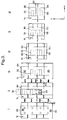
- Figure 3 illustrates the manufacturing sequence in plan view.
- the blank 14 is placed on the table 34.
- the divisions 56 are placed on the glued region 44 of the blank 14.
- adhesive is applied to the edge 83.
- end panels 86, 88 of the blank 14 are folded upwardly towards the vertical by folding belts (not shown).
- the end panels 86, 88 have been folded by the belts 90° through the vertical and are being folded through a further 90° towards the horizontal.
- the panels 86, 88 have been folded through 180° so that panel edge 83 overlies and is fastened to glue flap 84 to form the sleeve.
- Figures 4a-h are plan illustrations of various case and division combinations possible in accordance with the invention.
- Figure 4a shows a 2x2 cell case in which the division sheets are fastened to adjacent case panels which are not the blank end panels and therefore do not border the sleeve glued joint ("manufacturer's joint"). The free ends of the sheets terminate slightly more than half way across the adjacent cells, short of the opposite case wall.
- Figure 4b shows a 2x3 case in which all division sheets are fastened to two adjacent case panels not forming the sleeve joint. Two of the sheets are formed from a single U-shaped piece of board and the free ends of all three sheets terminate short of the adjacent case walls.
- Figure 4c is the same as figure 4b except that the longitudinal sheet is free at both ends and for stability of the divisions during case filling extends the entire length of the case.
- Figures 4d and 4e show 3x4 cases with the two longitudinal sheets fixed to the same panel with their free ends terminating short of the opposite panel.
- the longitudinal sheets are L-shaped, with the foot of the L secured to the case (like figure 4a).
- the longitudinal sheets are formed from a single U-shaped piece of board, with the base of the U secured to the case (like figure 4c).
- Figure 4f is like figure 4d, except that two of the transverse sheets terminate short of the adjacent case panels.
- the third transverse sheet extends the full width of the case.
- the joint forming the sleeve is also at a different corner compared to fig. 4d, but still does not border the panel to which the division sheets are fixed.
- two sheets of a set of 3x4 cell divisions are shortened and secured to respective adjacent case panels.
- Figure 4h is similar, except that all the division sheets are shortened.
- the two secured divisions are those lying furthest from the corner formed by the two panels to which the sheets are attached.
- the foot of the L is folded to lie adjacent to the remainder of the sheet in the flattened division, for securing to the case blank 14.
- the resulting double thickness of material ensures that the sucker head 64 rests more evenly on the division and this, together with the slight resiliency at the fold line defining the foot of the L, ensures that glued joints are reliably produced.
- the foot of the L points towards the foldline on the blank 14 defining the corner of the case opposite to the sleeve joint. This ensures that the divisions overlie the central panels of the blank before folding, allowing the outer panels to be readily folded and joined to enfold the divisions.
- the divisions are self erecting when the case lies in any orientation.
- the divisions are self erecting when their sheets are vertically orientated, or with gravity assistance when the panel to which the division is attached lies uppermost in the flattened assembly.
- the division sheets it is possible for the division sheets to be attached to panels which border the sleeve joint.
Landscapes
- Engineering & Computer Science (AREA)
- Mechanical Engineering (AREA)
- Making Paper Articles (AREA)
Priority Applications (1)
| Application Number | Priority Date | Filing Date | Title |
|---|---|---|---|
| EP98300601A EP0933192A1 (fr) | 1998-01-28 | 1998-01-28 | Cartons et cloisons |
Applications Claiming Priority (1)
| Application Number | Priority Date | Filing Date | Title |
|---|---|---|---|
| EP98300601A EP0933192A1 (fr) | 1998-01-28 | 1998-01-28 | Cartons et cloisons |
Publications (1)
| Publication Number | Publication Date |
|---|---|
| EP0933192A1 true EP0933192A1 (fr) | 1999-08-04 |
Family
ID=8234639
Family Applications (1)
| Application Number | Title | Priority Date | Filing Date |
|---|---|---|---|
| EP98300601A Withdrawn EP0933192A1 (fr) | 1998-01-28 | 1998-01-28 | Cartons et cloisons |
Country Status (1)
| Country | Link |
|---|---|
| EP (1) | EP0933192A1 (fr) |
Citations (2)
| Publication number | Priority date | Publication date | Assignee | Title |
|---|---|---|---|---|
| US3813999A (en) * | 1972-10-02 | 1974-06-04 | Union Camp Corp | Apparatus for combining partition and box blank |
| EP0042748A1 (fr) * | 1980-06-25 | 1981-12-30 | Despack Limited | Dispositif de fabrication d'un carton |
-
1998
- 1998-01-28 EP EP98300601A patent/EP0933192A1/fr not_active Withdrawn
Patent Citations (2)
| Publication number | Priority date | Publication date | Assignee | Title |
|---|---|---|---|---|
| US3813999A (en) * | 1972-10-02 | 1974-06-04 | Union Camp Corp | Apparatus for combining partition and box blank |
| EP0042748A1 (fr) * | 1980-06-25 | 1981-12-30 | Despack Limited | Dispositif de fabrication d'un carton |
Similar Documents
| Publication | Publication Date | Title |
|---|---|---|
| AU604411B2 (en) | Method and machine for forming cases with polygonal section made from a sheet material and cases thus obtained | |
| US11530058B2 (en) | System and method for automatically closing boxes with cardboard lids | |
| US6015084A (en) | Set of blanks, box, method and machine for making a box from said set of blanks | |
| US20050124478A1 (en) | Side wall flap folding mechanism for carton forming machine | |
| CA2431344C (fr) | Machine de montage de boites en carton | |
| JPH09314700A (ja) | 紙製折箱製函機 | |
| EP0685328B1 (fr) | Plieuse à poches | |
| JP3483471B2 (ja) | コーナー補強型トレーの製函機 | |
| JPH07102635B2 (ja) | 組み立て箱製造装置 | |
| US4189089A (en) | Bag having sides seamed by complementary bands of cohesive material | |
| JPH0769314A (ja) | タオル包装機 | |
| JP3213565B2 (ja) | 合成樹脂フィルム製ゴミ袋の製造方法および装置 | |
| US4785610A (en) | Automatic machine for packaging products of different kinds in boxes | |
| JPH08501034A (ja) | 書類挟みの製造方法および製造装置 | |
| US4636185A (en) | Apparatus for fabricating a box-like article | |
| US4342808A (en) | Roll stock for use in manufacture of bag | |
| JP2000506456A (ja) | 小冊子を製造する方法及び装置 | |
| US4184413A (en) | Apparatus for manufacturing a bag and delivering a bag in an open configuration to a check-out counter | |
| US4226172A (en) | Method for manufacturing a square bottom bag | |
| US2619275A (en) | Folding box employing nonscorable sheeting | |
| JPH05177744A (ja) | 製函方法及び装置 | |
| JP3396599B2 (ja) | 紙製ウエ−ブクッション入り封筒の製造方法及びその製造装置 | |
| JPS58116142A (ja) | 弁付紙袋製造装置 | |
| JP3641835B2 (ja) | カートンブランクの折りぐせ装置 | |
| JPS61241133A (ja) | 製函方法及び製函装置 |
Legal Events
| Date | Code | Title | Description |
|---|---|---|---|
| PUAI | Public reference made under article 153(3) epc to a published international application that has entered the european phase |
Free format text: ORIGINAL CODE: 0009012 |
|
| AK | Designated contracting states |
Kind code of ref document: A1 Designated state(s): AT BE CH DE DK ES FI FR GB GR IE IT LI LU MC NL PT SE |
|
| AX | Request for extension of the european patent |
Free format text: AL;LT;LV;MK;RO;SI |
|
| AKX | Designation fees paid | ||
| REG | Reference to a national code |
Ref country code: DE Ref legal event code: 8566 |
|
| STAA | Information on the status of an ep patent application or granted ep patent |
Free format text: STATUS: THE APPLICATION IS DEEMED TO BE WITHDRAWN |
|
| 18D | Application deemed to be withdrawn |
Effective date: 20000205 |