EP0933193B1 - Verfahren und Vorrichtung zur Herstellung eines mit einem Reissverschluss wiederverschliessbaren Beutels - Google Patents
Verfahren und Vorrichtung zur Herstellung eines mit einem Reissverschluss wiederverschliessbaren Beutels Download PDFInfo
- Publication number
- EP0933193B1 EP0933193B1 EP99300747A EP99300747A EP0933193B1 EP 0933193 B1 EP0933193 B1 EP 0933193B1 EP 99300747 A EP99300747 A EP 99300747A EP 99300747 A EP99300747 A EP 99300747A EP 0933193 B1 EP0933193 B1 EP 0933193B1
- Authority
- EP
- European Patent Office
- Prior art keywords
- zipper
- web
- placement head
- segment
- zipper segment
- Prior art date
- Legal status (The legal status is an assumption and is not a legal conclusion. Google has not performed a legal analysis and makes no representation as to the accuracy of the status listed.)
- Expired - Lifetime
Links
Images




Classifications
-
- B—PERFORMING OPERATIONS; TRANSPORTING
- B31—MAKING ARTICLES OF PAPER, CARDBOARD OR MATERIAL WORKED IN A MANNER ANALOGOUS TO PAPER; WORKING PAPER, CARDBOARD OR MATERIAL WORKED IN A MANNER ANALOGOUS TO PAPER
- B31B—MAKING CONTAINERS OF PAPER, CARDBOARD OR MATERIAL WORKED IN A MANNER ANALOGOUS TO PAPER
- B31B70/00—Making flexible containers, e.g. envelopes or bags
-
- B—PERFORMING OPERATIONS; TRANSPORTING
- B31—MAKING ARTICLES OF PAPER, CARDBOARD OR MATERIAL WORKED IN A MANNER ANALOGOUS TO PAPER; WORKING PAPER, CARDBOARD OR MATERIAL WORKED IN A MANNER ANALOGOUS TO PAPER
- B31B—MAKING CONTAINERS OF PAPER, CARDBOARD OR MATERIAL WORKED IN A MANNER ANALOGOUS TO PAPER
- B31B70/00—Making flexible containers, e.g. envelopes or bags
- B31B70/74—Auxiliary operations
- B31B70/81—Forming or attaching accessories, e.g. opening devices, closures or tear strings
- B31B70/813—Applying closures
-
- B—PERFORMING OPERATIONS; TRANSPORTING
- B31—MAKING ARTICLES OF PAPER, CARDBOARD OR MATERIAL WORKED IN A MANNER ANALOGOUS TO PAPER; WORKING PAPER, CARDBOARD OR MATERIAL WORKED IN A MANNER ANALOGOUS TO PAPER
- B31B—MAKING CONTAINERS OF PAPER, CARDBOARD OR MATERIAL WORKED IN A MANNER ANALOGOUS TO PAPER
- B31B2160/00—Shape of flexible containers
- B31B2160/10—Shape of flexible containers rectangular and flat, i.e. without structural provision for thickness of contents
-
- B—PERFORMING OPERATIONS; TRANSPORTING
- B31—MAKING ARTICLES OF PAPER, CARDBOARD OR MATERIAL WORKED IN A MANNER ANALOGOUS TO PAPER; WORKING PAPER, CARDBOARD OR MATERIAL WORKED IN A MANNER ANALOGOUS TO PAPER
- B31B—MAKING CONTAINERS OF PAPER, CARDBOARD OR MATERIAL WORKED IN A MANNER ANALOGOUS TO PAPER
- B31B70/00—Making flexible containers, e.g. envelopes or bags
- B31B70/74—Auxiliary operations
- B31B70/81—Forming or attaching accessories, e.g. opening devices, closures or tear strings
- B31B70/813—Applying closures
- B31B70/8131—Making bags having interengaging closure elements
- B31B70/8133—Applying the closure elements in the cross direction
Definitions
- the invention relates to a method and apparatus for manufacturing a bag with a reclosable zipper.
- United States Patent Number 4,909,017 issued to McMahon et al. is an example of a conventional resealable bag manufacturing apparatus, whereby fastener strips are secured to a continuous length of film which is then formed into a tube and into a series of completed resealable bags.
- the invention provides a method and apparatus in which an elongated web of bag film is fed under an in-line zipper applicator which includes a placement head.
- the invention provides a method of manufacturing a bag with a reclosable zipper, the method comprising the steps of:
- the web feed is stopped, and a zipper segment is placed on the web by the placement head so that the zipper segment extends perpendicular to the longitudinal axis of the web.
- the zipper placement head cooperates with a seal bar to seal the zipper segment to the web. After the zipper segment is sealed to the web, more web is fed under the placement head to receive the next zipper segment, and the attached zipper segment is carried away with the moving web.
- the invention also provides an apparatus for manufacturing a bag with a reclosable zipper from a continuous web of bag film having a longitudinal axis and a continuous length of zipper assembly having male and female strips of zipper engaged so that the zipper is in the closed condition, the apparatus comprising a placement head movable in a generally perpendicular direction with respect to the web, the placement head being adapted to support a segment of the zipper assembly, the zipper segment having male and female strips and having a length approximately one-half the width of the web, the placement head including a support strip adapted to extend between the male and female strips of the zipper segment, and a plurality of floating rollers adapted to hold the zipper segment against the support strip, the rollers being oriented such that rotation of the rollers maintains the zipper segment in the desired position in the placement head.
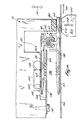
- FIG. 1 illustrates an apparatus 10 for manufacturing plastic bags with reclosable zippers.
- Each bag (not shown) has a width 14, a length 18, and a mouth with a resealable zipper.
- FIG. 2 illustrates a zipper assembly 22 that is fed into the apparatus 10.
- the zipper assembly 22 which is shown in the closed condition, includes a first flange or female strip 26 having a top surface 30 and a bottom surface 34, a second flange or male strip 38, and a zipper 42 between the first and second flanges 26, 38.
- the zipper 42 includes a female portion 46 attached to or formed integrally with the first flange 26, and a male portion 50 attached to or formed integrally with the second flange 38.
- the entire zipper assembly 22 is preferably made of extruded plastic.
- the second flange 38 includes first and second portions 62, 66.
- the first portion 62 of the second flange 38 is positioned opposite the first flange 26, and is substantially the same size as the first flange 26.
- the zipper assembly 22 is acted upon by a servo driven roller 70 and a tension roller 74, which feed the zipper assembly 22 through a guide and track 78.
- the zipper assembly 22 travels in a first direction 82 through a zipper knife assembly 86, shown in FIGS. 1 and 7.
- the zipper knife assembly 86 includes a shear plate 90 having a profiled slot 94 through which the zipper assembly 22 passes.
- the zipper knife assembly 86 also includes a zipper knife 98 that is held against the shear plate 90 by a disc spring 102 and fastener 106.
- the zipper placement head 110 is movable along a vertical line 114 as shown in FIG. 1 between an "up" position 118 (shown in solid lines) and a “down" position 122 (shown in broken lines).
- the zipper placement head 110 is in the up position when it receives the zipper assembly 22.
- the zipper placement head 110 best seen in FIGS. 3-6, has a width 126 that is substantially equal to the width 14 of the plastic bag produced by the manufacturing system 10.
- the placement head 110 includes a support strip 130 having a top surface 134.
- the support strip 130 is positioned along the entire width 126 of the placement head 110.
- the support strip 130 is preferably made of stainless steel.
- the placement head 110 also includes a cavity 138 along a bottom portion 142 of the placement head 110.
- the support strip 130 is attached to the placement head 110 by a plurality of screws 146, and extends horizontally into the cavity 138.
- each recess 150 housing a dowel pin or roller 154.
- Each dowel pin 154 has a diameter 158.
- Each dowel pin 154 is free-floating in its corresponding recess 150, such that the dowel pin 154 projects out of an open end 162 of the recess 150 and rests on the top surface 134 of the support strip 130.
- the dowel pin 154 projects from the recess 150 a distance less than half the diameter 158 of the dowel pin 154, and preferably as little as practical, to ensure that the dowel pin 154 will not come entirely out of the recess 150 unless the support strip 130 is removed from the placement head 110.
- the recesses 150 are oriented with respect to a second direction 166 (the direction of movement of the bag film, as explained below) such that the axis of rotation 170 of each dowel pin 154 is oriented at an angle 174 with respect to the second direction 166 as shown in FIG. 6.
- the second direction 166 is substantially perpendicular to the first direction 82.
- the bottom surface 34 of the first flange 26 slides along the top surface 134 of the support strip 130, and the top surface 30 of the first flange 26 moves beneath the dowel pins 154.
- the dowel pins 154 therefore, rest on the top surface 30 of the first flange 26.
- the weight of the dowel pins 154 helps to hold the first flange 26 against the support strip 130. Also, frictional forces between the top surface 30 of the first flange 26 and the dowel pins 154 cause the dowel pins 154 to rotate in a clockwise direction 178 as seen in FIG. 5. Because of the angle 174 of the axes 170 of the dowel pins 154, and because of the friction between the dowel pins 154 and the top surface 30 of the first flange 26, the dowel pins 154 also tend to urge the zipper assembly 22 in a direction 182 (Fig. 6) perpendicular to the axes of rotation 170 as the dowel pins 154 rotate, thereby ensuring that the zipper assembly 22 is held in the zipper placement head 110.
- the placement head 110 also includes a resilient strip 186 attached along the width of the placement head 110.
- the resilient strip 186 is preferably a silicone rubber strip.
- the rollers 70, 74 stop rotating, and the knife 98 operates on the zipper assembly 22.
- the placement head 110 is in the up position 118, it is positioned in close proximity to the shear plate 90. Again referring to FIG. 7, the spring action of the spring 102 holds the knife 98 against the shear plate 90, and thereby creates a shearing force on the zipper assembly 22 and severs the zipper assembly 22. In this manner, a zipper segment of a length substantially equal to the width 126 of the placement head 110 is created, and the zipper segment is held in the cavity 138 of the placement head 110.
- a web of plastic bag film 194 having a longitudinal axis 198 and a width 202 is fed in the second direction 166 along the longitudinal axis 198 by a drive mechanism (not shown).
- the length of the zipper segment and the width 126 of the placement head 110 are both approximately one half the width 202 of the web 194.
- the placement head 110 is substantially centered over the width 202 of the web 194.
- the width 202 of the plastic web 194 is substantially twice the width 14 of the plastic bag.
- a desired length of web 194 equal to approximately the length 18 of the plastic bag, travels beneath the zipper placement head 110, the drive mechanism stops feeding the web 194, and the web 194 comes to a stop. Then the placement head 110 is moved to the down position 122, where it is in close proximity to the web 194.
- a cylinder or seal bar 210 is positioned beneath the web 194, and extends a length (not shown) substantially equal to the width 126 of the placement head 110.
- the cylinder 210 has a hot surface 214.
- the cylinder 210 is aligned with the resilient strip 186 of the placement head 110, and is movable along a vertical line 218 between an engaging position (not shown) wherein the cylinder 210 compresses a portion of the web 194 against the resilient strip 186, and a disengaging position 222 (shown in FIG. 4), wherein the cylinder 210 allows the web 194 to pass between the cylinder 210 and the placement head 110.
- the hot surface 214 heats the web 194 and second portion 66 of the second flange 38, and the cylinder 210 presses the web 194 and second portion 66 against the resilient strip 186, thereby causing the web 194 to fuse to the second portion 66 of the second flange 38.
- the zipper segment is attached to the web 194 perpendicular to the web longitudinal axis 198.
- a resilient strip works best for ensuring a reliable seal along the entire length of the zipper segment between the web 194 and the second portion 66 of the second flange 38. It is also possible to obtain a good seal between the web 194 and the zipper segment using a non-resilient strip of metal or other hard substance, but such a seal cannot be obtained as reliably and consistently as when a resilient strip is used.
- the placement head 110 is raised to the up position 118, and the web 194 is advanced in the second direction 166 by the drive mechanism. As the placement head 110 is raised and the web 194 advanced, the zipper segment is pulled off the support strip 130 and under the resilient strip 186, and is carried away by the web 194.
- the process described above then repeats, with another length of zipper assembly 22 being fed into the placement head 110 and cut with the knife 98 to create a zipper segment held in the cavity 138 of the placement head 110.
- the web 194 is again advanced in the second direction 166 a distance equal to the length 18 of the plastic bag, and the placement head 110 is lowered to a position 122 closely proximate to the web 194.
- the cylinder 210 is again raised to the engaging position where heat and pressure are applied to the web 194, thereby fusing the zipper segment to the web 194.
- the placement head 110 again raises and the web 194 again carries the zipper segment away.
- the web 194 is moved by the drive mechanism to a conventional vertical form, fill, and seal machine (not shown), where the web 194 is folded over the zipper segment (partially shown in Fig. 8) and sealed to the first flange 26 to form the bag, which is then filled with product and the top of the bag sealed for shipping.
Landscapes
- Making Paper Articles (AREA)
Claims (9)
- Verfahren zur Herstellung eines Beutels mit einem wiederverschließbaren Reißverschluß (42), wobei das Verfahren die folgenden Schritte ausweist:(a) Bereitstellen einer länglichen Bahn der Beutelfolie (194) mit einer Längsachse (198) und mit einer Breite (202) in einer Richtung senkrecht zur Achse;(b) Bereitstellen eines Reißverschlußsegmentes (22), das einen mit Vorsprüngen versehenen und einen aufnehmenden Streifen (50, 46) des Reißverschlusses umfaßt, die so in Eingriff kommen, daß sich das Reißverschlußsegment im geschlossenen Zustand befindet, wobei das Reißverscblußsegment eine Länge aufweist, die annähernd die Hälfte der Breite der Bahn ist, wobei einer von dem mit Vorsprüngen versehenen und dem aufnehmenden Streifen einen Flansch (26) umfaßt;(c) Bereitstellen eines Reißverschlußeinbringungskopfes (110) mit einem Stützstreifen (130);(d) Einsetzen des Reißverschlußsegmentes in den Einsetzkopf, der den Reißverschlußsegmentflansch mit dem Stützstreifen zwischen dem mit Vorsprüngen versehenen und dem aufnehmenden Streifen des Reißverschlußsegmentes stützt, so daß sich das Reißverschlußsegment im allgemeinen senkrecht zur Achse erstreckt, und so, daß sich das Reißverschlußsegment nur teilweise über die Bahn erstreckt;(e) Bewegen des Einsetzkopfes und des Reißverschlußsegmentes im allgemeinen senkrecht zur und in Richtung der Bahn;(f) Abdichten von einem des mit Vorsprüngen versehenen und des aufnehmenden Streifens des Reißverschlußsegmentes mit der Bahn;(g) Entfernen des Reißverschlußsegmentes aus dem Einsetzkopf; und(h) Falten der Bahn über den anderen des mit Vorsprüngen versehenen und des aufnehmenden Streifens des Reißverschlußsegmentes und Abdichten der Bahn daran, um so einen Beutel mit dem Reißverschluß in der Öffnung des Beutels herzustellen.
- Verfahren nach Anspruch 1, bei dem
der Schritt (a) das Bereitstellen einer kontinuierlichen Zuführung einer länglichen Bahn der Beutelfolie in einer Richtung im allgemeinen parallel zur Längsachse umfaßt; und
der Schritt (b) das Bereitstellen einer kontinuierlichen Zuführung einer Reißverschlußeinheit in einer Richtung im allgemeinen senkrecht zur Längsachse umfaßt. - Verfahren nach Anspruch 1, bei dem der Schritt (g) das Bewegen der Bahn in einer Richtung parallel zur Längsachse umfaßt.
- Verfahren nach Anspruch 1, bei dem der Schritt (f) das Abdichten des einen von dem mit Vorsprüngen versehenen und dem aufnehmenden Streifen des Reißverschlußsegmentes in einer Position umfaßt, die im wesentlichen mit Bezugnahme auf die seitlichen Ränder der Bahn zentriert ist.
- Verfahren nach Anspruch 1, bei dem der Stützstreifen eine obere Fläche (134) aufweist, worin der Einsetzkopf darin über dem Stützstreifen eine Reihe von Aussparungen (150) aufweist, wobei eine jede Aussparung eine frei bewegliche Rolle (154) aufnimmt, die auf der oberen Fläche des Stützstreifens aufliegt, wenn sich das Reißverschlußsegment nicht im Einsetzkopf befindet, so daß, wenn sich das Reißverschlußsegment in den Einsetzkopf bewegt, ein Abschnitt des Reißverschlußsegmentes längs der oberen Fläche des Stützstreifens gleitet, und die obere Fläche (30) des Reißverschlußsegmentabschnittes bewegt sich unterhalb der Rollen, so daß Reibungskräfte zwischen dem Reißverschlußabschnitt und den Rollen bewirken, daß sich die Rollen drehen, und dadurch das Reißverschlußsegment in eine Richtung treiben, die das Reißverschlußsegment im Einsetzkopf hält.
- Verfahren nach Anspruch 5, bei dem der Schritt (g) das Bewegen des Einsetzkopfes weg von der Bahn und das Bewegen der Bahn so umfaßt, daß das Reißverschlußsegment vom Stützstreifen weggezogen und mittels der Bahn weggeführt wird.
- Verfahren nach Anspruch 6, bei dem der Einsetzkopf ebenfalls einen elastischen Streifen (186) umfaßt, der so positioniert ist, daß, wenn sich das Reißverschlußsegment in den Einsetzkopf bewegt, ein Abschnitt des Reißverschlußsegmentes unterhalb des elastischen Streifens positioniert wird, und bei dem der Schritt (f) das Zusammendrücken eines Abschnittes der Bahn gegen den elastischen Streifen umfaßt
- Verfahren nach Anspruch 1, bei dem der Schritt (c) das Bereitstellen von mindestens einer Rolle (154) umfaßt, die unter einem Winkel von weniger als 90° und größer als 0° relativ zum Reißverschlußsegment positioniert ist, und bei dem der Schritt (d) das Einsetzen des Reißverschlußsegmentes in den Einsetzkopf und das Drehen der Rolle umfaßt, um den Reißverschluß im Einsetzkopf zu halten.
- Vorrichtung (10) zum Herstellen eines Beutels mit einem wiederverschließbaren Reißverschluß (42) aus einer kontinuierlichen Bahn der Beutelfolie (194), die eine Längsachse (198) aufweist, und wobei eine kontinuierliche Länge der Reißverschlußeinheit (22) einen mit Vorsprüngen versehenen und einen aufnehmenden Streifen des Reißverschlusses (50, 46) aufweist, die so in Eingriff gebracht werden, daß sich der Reißverschluß im geschlossenen Zustand befindet, wobei die Vorrichtung einen Einsetzkopf (110) aufweist, der in einer im allgemeinen senkrechten Richtung mit Bezugnahme auf die Bahn beweglich ist, wobei der Einsetzkopf so angepaßt ist, daß er ein Segment der Reißverschlußeinheit trägt, wobei das Reißverschlußsegment einen mit Vorsprüngen versehenen und einen aufnehmenden Streifen (50, 46) und eine Länge aufweist, die annähernd eine Hälfte der Breite der Bahn (202) beträgt, wobei der Einsetzkopf einen Stützstreifen (130), der so ausgeführt ist, daß er sich zwischen dem mit Vorsprüngen versehenen und dem aufnehmenden Streifen des Reißverschlußsegmentes erstreckt, und eine Vielzahl von freibeweglichen Rollen (154) umfaßt, die so ausgeführt sind, daß sie das Reißverschlußsegment gegen den Stützstreifen halten, wobei die Rollen so ausgerichtet sind, daß die Drehung der Rollen das Reißverschlußsegment in der gewünschten Position im Einsetzkopf hält.
Applications Claiming Priority (2)
| Application Number | Priority Date | Filing Date | Title |
|---|---|---|---|
| US7334398P | 1998-02-02 | 1998-02-02 | |
| US73343P | 1998-02-02 |
Publications (3)
| Publication Number | Publication Date |
|---|---|
| EP0933193A2 EP0933193A2 (de) | 1999-08-04 |
| EP0933193A3 EP0933193A3 (de) | 2000-03-29 |
| EP0933193B1 true EP0933193B1 (de) | 2003-10-22 |
Family
ID=22113175
Family Applications (1)
| Application Number | Title | Priority Date | Filing Date |
|---|---|---|---|
| EP99300747A Expired - Lifetime EP0933193B1 (de) | 1998-02-02 | 1999-02-02 | Verfahren und Vorrichtung zur Herstellung eines mit einem Reissverschluss wiederverschliessbaren Beutels |
Country Status (3)
| Country | Link |
|---|---|
| US (1) | US6099451A (de) |
| EP (1) | EP0933193B1 (de) |
| DE (1) | DE69912167T2 (de) |
Families Citing this family (17)
| Publication number | Priority date | Publication date | Assignee | Title |
|---|---|---|---|---|
| US7182513B1 (en) * | 1996-05-21 | 2007-02-27 | Illinois Tool Works Inc. | Zipper strip and method of positioning the strip transverse longitudinal axis |
| JP2000334860A (ja) * | 1999-05-27 | 2000-12-05 | R:Kk | 圧縮保存袋の製造方法 |
| GB9922747D0 (en) * | 1999-09-24 | 1999-11-24 | Molins Plc | Method and apparatus for producing bags having a reclosable fastener |
| DK1106506T3 (da) * | 1999-12-03 | 2004-07-12 | Sig Pack Systems Ag | Fremgangsmåde og indretning til fremstilling af 3-seglrandposer med indsvejset lukkeprofil |
| US6530870B2 (en) * | 2000-04-27 | 2003-03-11 | Reynolds Consumer Products, Inc. | Methods of manufacturing reclosable packages; and packages made thereby |
| GB0017307D0 (en) * | 2000-07-15 | 2000-08-30 | Supreme Plastics Group Ltd | Methods of and apparatus for sealing zipper to a substrate |
| US6620087B1 (en) * | 2000-09-06 | 2003-09-16 | Illinois Tool Works Inc. | Zipper segment for transverse direction application to a bag film |
| US7413535B2 (en) * | 2001-07-27 | 2008-08-19 | Illinois Tool Works Inc. | Method for manufacturing tamper evident reclosable plastic bags |
| US6756097B2 (en) * | 2001-10-25 | 2004-06-29 | Ccl Label, Inc. | Re-sealable bag closure label and related method of manufacture |
| US6902091B2 (en) * | 2001-10-30 | 2005-06-07 | Illinois Tool Works Inc. | Method and apparatus for feeding slider-zipper tape to application station |
| US6820394B2 (en) * | 2002-03-25 | 2004-11-23 | Illinois Tool Works Inc. | Method for forming zippered thermoformed packages |
| US6709157B2 (en) * | 2002-04-25 | 2004-03-23 | Reynolds Consumer Products, Inc. | Closure arrangement with tear guide for allowing access to zipper flanges in a package |
| US7092942B2 (en) * | 2002-05-31 | 2006-08-15 | Bea Systems, Inc. | Managing secure resources in web resources that are accessed by multiple portals |
| US6840897B2 (en) * | 2002-07-18 | 2005-01-11 | Illinois Tool Works Inc. | Zipper applicator |
| US6810642B2 (en) * | 2002-08-05 | 2004-11-02 | Illinois Tool Works Inc. | Method and apparatus for sealing zippers to bag making film |
| US20090257686A1 (en) * | 2008-04-14 | 2009-10-15 | Illinois Tool Works Inc. | Flow-wrapper package with reclosure |
| ITRM20130322A1 (it) * | 2013-06-03 | 2014-12-04 | Bosshart & Neupack Emballagen Bne Ag | Chiusura a profili complementari e macchina per applicare la suddetta chiusura ad una pellicola sottile. |
Family Cites Families (12)
| Publication number | Priority date | Publication date | Assignee | Title |
|---|---|---|---|---|
| US4617683A (en) * | 1984-01-30 | 1986-10-14 | Minigrip, Inc. | Reclosable bag, material, and method of and means for making same |
| US4709398A (en) * | 1987-01-07 | 1987-11-24 | Minigrip, Inc. | Chain bags, method and apparatus |
| US4878987A (en) * | 1987-03-16 | 1989-11-07 | Minigrip, Inc. | Transverse zipper bag material and method of and means for making same |
| US4894975A (en) * | 1988-03-09 | 1990-01-23 | Minigrip, Inc. | Method and apparatus for making reclosable bags with fastener strips in a form fill and seal machine |
| US4909017B1 (en) * | 1989-07-28 | 1999-02-09 | Minigrip Inc | Reclosable bag material method and apparatus |
| US5573614A (en) * | 1993-12-28 | 1996-11-12 | Minigrip, Inc. | Method for stabilizing a plastic zipper during attachment to a film |
| US5529659A (en) * | 1994-11-25 | 1996-06-25 | Proven Designs, Inc. | Machine and associated apparatus for attaching zippers to plastic bags |
| US5557907A (en) * | 1995-02-24 | 1996-09-24 | Illinois Tool Works Inc. | Transverse zipper system |
| US5672234A (en) * | 1995-04-28 | 1997-09-30 | Park-Air Corporation | Zipper fusing machine for attaching zipper material to a plastic web |
| FI980288A7 (fi) * | 1995-08-09 | 1998-02-09 | James Worth Yeager | Vetoketjulla varustettu kalvo ja pussi |
| FR2745261B1 (fr) * | 1996-02-27 | 1998-05-07 | Flexico France Sarl | Machine de formation, remplissage et fermeture automatique de sacs, a profiles de fermeture transversaux |
| US5951453A (en) * | 1996-11-15 | 1999-09-14 | Innoflex Incorporated | Recloseable bag assembly and method of making same |
-
1999
- 1999-02-01 US US09/241,564 patent/US6099451A/en not_active Expired - Lifetime
- 1999-02-02 DE DE69912167T patent/DE69912167T2/de not_active Expired - Lifetime
- 1999-02-02 EP EP99300747A patent/EP0933193B1/de not_active Expired - Lifetime
Also Published As
| Publication number | Publication date |
|---|---|
| EP0933193A3 (de) | 2000-03-29 |
| EP0933193A2 (de) | 1999-08-04 |
| DE69912167T2 (de) | 2004-08-12 |
| DE69912167D1 (de) | 2003-11-27 |
| US6099451A (en) | 2000-08-08 |
Similar Documents
| Publication | Publication Date | Title |
|---|---|---|
| EP0933193B1 (de) | Verfahren und Vorrichtung zur Herstellung eines mit einem Reissverschluss wiederverschliessbaren Beutels | |
| US4094729A (en) | Apparatus for making open profile bags | |
| US7036987B2 (en) | Reclosable bag having wicket flap and slider-actuated string zipper | |
| US7552573B2 (en) | Method for placing a product in a flexible recloseable container | |
| US4878987A (en) | Transverse zipper bag material and method of and means for making same | |
| US6622353B2 (en) | Slider-operated fastener with spaced notches and associated preseals | |
| US6871473B1 (en) | Method and apparatus for making reclosable plastic bags using a pre-applied slider-operated fastener | |
| US6895725B2 (en) | Method and apparatus for sealing zippers to bag making film | |
| US6675558B2 (en) | Method for manufacturing flexible packages having slide closures | |
| US6526726B1 (en) | Method of applying a slider to a fastener-carrying plastic web | |
| WO1998003328B1 (en) | Fastener tape material, bag utilizing fastener tape material, and method of manufacture thereof | |
| US20050008266A1 (en) | Reclosable package having internal seal made of double-sided adhesive tape | |
| EP1447340A1 (de) | Beutel mit einer Aufhängevorrichtung und einem Reissverschluss mit Schieber | |
| US7229511B2 (en) | Method and apparatus for feeding slider-zipper assemblies | |
| US7114309B2 (en) | Method and apparatus for making reclosable packages having slider-actuated string zippers | |
| US6884208B2 (en) | Method and apparatus for making reclosable bags having slider-actuated string zippers | |
| US6929594B2 (en) | Belt drive assembly for feeding zipper tape | |
| US20060079386A1 (en) | Method and apparatus for making slider-operated string-zippered bag with transverse application of zipper | |
| AU2004264406B2 (en) | Method and apparatus for inserting sliders during automated manufacture of reclosable bags | |
| US20040007309A1 (en) | Tack knife |
Legal Events
| Date | Code | Title | Description |
|---|---|---|---|
| PUAI | Public reference made under article 153(3) epc to a published international application that has entered the european phase |
Free format text: ORIGINAL CODE: 0009012 |
|
| AK | Designated contracting states |
Kind code of ref document: A2 Designated state(s): DE GB NL |
|
| AX | Request for extension of the european patent |
Free format text: AL;LT;LV;MK;RO;SI |
|
| PUAL | Search report despatched |
Free format text: ORIGINAL CODE: 0009013 |
|
| AK | Designated contracting states |
Kind code of ref document: A3 Designated state(s): AT BE CH CY DE DK ES FI FR GB GR IE IT LI LU MC NL PT SE |
|
| AX | Request for extension of the european patent |
Free format text: AL;LT;LV;MK;RO;SI |
|
| 17P | Request for examination filed |
Effective date: 20000530 |
|
| AKX | Designation fees paid |
Free format text: DE GB NL |
|
| 17Q | First examination report despatched |
Effective date: 20020221 |
|
| RIC1 | Information provided on ipc code assigned before grant |
Ipc: 7B 31B 21/00 B Ipc: 7B 31B 1/90 A |
|
| GRAH | Despatch of communication of intention to grant a patent |
Free format text: ORIGINAL CODE: EPIDOS IGRA |
|
| GRAS | Grant fee paid |
Free format text: ORIGINAL CODE: EPIDOSNIGR3 |
|
| GRAA | (expected) grant |
Free format text: ORIGINAL CODE: 0009210 |
|
| AK | Designated contracting states |
Kind code of ref document: B1 Designated state(s): DE GB NL |
|
| REG | Reference to a national code |
Ref country code: GB Ref legal event code: FG4D |
|
| RIN1 | Information on inventor provided before grant (corrected) |
Inventor name: MULDER, STEVEN C. |
|
| REF | Corresponds to: |
Ref document number: 69912167 Country of ref document: DE Date of ref document: 20031127 Kind code of ref document: P |
|
| PLBE | No opposition filed within time limit |
Free format text: ORIGINAL CODE: 0009261 |
|
| STAA | Information on the status of an ep patent application or granted ep patent |
Free format text: STATUS: NO OPPOSITION FILED WITHIN TIME LIMIT |
|
| 26N | No opposition filed |
Effective date: 20040723 |
|
| REG | Reference to a national code |
Ref country code: DE Ref legal event code: R079 Ref document number: 69912167 Country of ref document: DE Free format text: PREVIOUS MAIN CLASS: B31B0001900000 Ipc: B31B0050810000 |
|
| PGFP | Annual fee paid to national office [announced via postgrant information from national office to epo] |
Ref country code: NL Payment date: 20180221 Year of fee payment: 20 |
|
| PGFP | Annual fee paid to national office [announced via postgrant information from national office to epo] |
Ref country code: GB Payment date: 20180221 Year of fee payment: 20 |
|
| PGFP | Annual fee paid to national office [announced via postgrant information from national office to epo] |
Ref country code: DE Payment date: 20180426 Year of fee payment: 20 |
|
| REG | Reference to a national code |
Ref country code: DE Ref legal event code: R071 Ref document number: 69912167 Country of ref document: DE |
|
| REG | Reference to a national code |
Ref country code: NL Ref legal event code: MK Effective date: 20190201 |
|
| REG | Reference to a national code |
Ref country code: GB Ref legal event code: PE20 Expiry date: 20190201 |
|
| PG25 | Lapsed in a contracting state [announced via postgrant information from national office to epo] |
Ref country code: GB Free format text: LAPSE BECAUSE OF EXPIRATION OF PROTECTION Effective date: 20190201 |