EP0933208A2 - Système de transport et procédé pour transporter des formes imprimantes - Google Patents
Système de transport et procédé pour transporter des formes imprimantes Download PDFInfo
- Publication number
- EP0933208A2 EP0933208A2 EP99101829A EP99101829A EP0933208A2 EP 0933208 A2 EP0933208 A2 EP 0933208A2 EP 99101829 A EP99101829 A EP 99101829A EP 99101829 A EP99101829 A EP 99101829A EP 0933208 A2 EP0933208 A2 EP 0933208A2
- Authority
- EP
- European Patent Office
- Prior art keywords
- printing
- transport system
- printing form
- forme cylinder
- conveyor
- Prior art date
- Legal status (The legal status is an assumption and is not a legal conclusion. Google has not performed a legal analysis and makes no representation as to the accuracy of the status listed.)
- Granted
Links
Images






Classifications
-
- B—PERFORMING OPERATIONS; TRANSPORTING
- B41—PRINTING; LINING MACHINES; TYPEWRITERS; STAMPS
- B41F—PRINTING MACHINES OR PRESSES
- B41F27/00—Devices for attaching printing elements or formes to supports
- B41F27/12—Devices for attaching printing elements or formes to supports for attaching flexible printing formes
- B41F27/1206—Feeding to or removing from the forme cylinder
-
- B—PERFORMING OPERATIONS; TRANSPORTING
- B41—PRINTING; LINING MACHINES; TYPEWRITERS; STAMPS
- B41P—INDEXING SCHEME RELATING TO PRINTING, LINING MACHINES, TYPEWRITERS, AND TO STAMPS
- B41P2227/00—Mounting or handling printing plates; Forming printing surfaces in situ
- B41P2227/60—Devices for transferring printing plates
- B41P2227/62—Devices for introducing printing plates
-
- B—PERFORMING OPERATIONS; TRANSPORTING
- B41—PRINTING; LINING MACHINES; TYPEWRITERS; STAMPS
- B41P—INDEXING SCHEME RELATING TO PRINTING, LINING MACHINES, TYPEWRITERS, AND TO STAMPS
- B41P2227/00—Mounting or handling printing plates; Forming printing surfaces in situ
- B41P2227/60—Devices for transferring printing plates
- B41P2227/63—Devices for removing printing plates
Definitions
- the invention relates to a transport system for conveying Printing forms from a printing form stock on the lateral surface of a Forme cylinder according to the preamble of claim 1.
- Such a conveyor system is known from DE 36 30 876 A1.
- the first printing plate transport carrier passes in a printing plate unloading device to a printing plate Printing plate transport auxiliary carrier, which is arranged such that it the Printing units of the rotary printing machine bypasses, and the printing plates too transported to their predetermined destination to place them in one place unload on which a printing plate assembly robot the printing plates takes over.
- the pressure plate assembly robot places the pressure plate on the predetermined position on a plate cylinder.
- a particular advantage of the transport system according to the invention is that it is very compact and compared to conventional Transport systems has only a small number of components.
- the Accessibility to the forme cylinders in the printing units is ensured by the Transport system not affected.
- Transport system can be both bottom and top printing units serve.
- the transport system according to the invention can be automated and enables a quick exchange of the production change Printing plates.
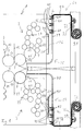
- a web-fed rotary printing press has a plurality of printing units or Printing units, with a printing unit being constructed, for example, like one Printing unit 1 (Fig. 1).
- the printing unit 1 has an overhead printing unit 2 and a printing unit 3 arranged underneath it and lying on it.
- Each of the two printing units 2, 3 has a forme cylinder 4 and 5 and a Transfer cylinder 6 or 7. This can be combined with another Transfer cylinder 8 and 9 cooperate, the one image to be printed each takes over from a forme cylinder 10 or 11.
- the printing units 2, 3 are used either for Printing on a single web of printing material or printing on two various printing material webs 12, 13, which can run, for example, as shown in FIGS. 1 to 10, with other path profiles also being conceivable; in particular, the printing units 2, 3 could also be used for direct printing with printing material webs 14, 15 (also shown in FIG. 1) between the forme cylinders 4 and 5 and the associated transfer cylinder 6 or 7 would run through. If the printing units 2 and 3 only for one-sided printing of the printing material webs 12, 13 are used instead of Transfer cylinders 8, 9 arranged corresponding printing cylinders.
- the forme cylinders 4, 5 each have two clamping channels 16, 17 and 18, 19.
- a transport system 24 which a first funding 25 to Conveying printing forms 26, 27 to the upper forme cylinder 4 and a lower one Conveying means 28 for conveying printing formes 29, 30 to the lower one Form cylinder 5 has.
- the funding 25, 28 each have a conveyor chain 37, 38 or a conveyor belt that is either finite or endless. In the event of Finite chains 37, 38 are chain stores 31, 32 for each conveyor 25, 28 and associated drive stations 33, 34 are provided. Since the forme cylinders 4, 5 Printing forms across their entire width, for example four adjacent printing forms, the transport system 24 is so wide like the printing unit 1.
- the conveying means 25, 28 are thus on a side wall attached, on the opposite side wall are corresponding Funding arranged.
- Conveyor belts or conveyor chains 37, 38 are available for the upper printing unit 2 and the lower printing unit 3 by a synchronous shaft 35 and 36, respectively be synchronized with each other.
- the conveyor chains 37, 38 or conveyor belts run in guide rails 39, 40.
- the printing units 2, 3 have only a small width, one only conveyor chain in one side wall should be sufficient. As a rule are however two conveyor chains on the opposite sides are necessary.
- To the Ends of the conveyor chains or conveyor belts 37, 38 are holding devices 41, 42 for receiving the printing forms 26, 27 and 29, 30, respectively Printing form stores 43, 44 and for delivery on the lateral surfaces of the Forme cylinders 4, 5 available.
- the receiving devices 41, 42 are as wide as the clear width of the printing unit side walls and in each of the conveyor chains 37, 38 fixed by two holding connections 60, 61 and 62, 63, respectively.
- the Retaining connections 60, 62 allow only one rotary movement and fix thus the position of the receiving devices 41, 42 on the conveyor chains 37, 38, while the holding connections 61, 64 a rotating and sliding movement allow so that when the conveyor chains 37, 38 move around an arc Length compensation can take place.
- Each of the receiving devices 41, 42 has Suction pad 45 and pressure or guide rollers 46a, 46b and 46c.
- the suction pads 45 are used to hold the receiving device 41, 42 initially lying printing form, here the printing forms 26, 29 from the Printing form memory 43 and 44, respectively.
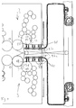
- the conveyor belts or conveyor chains 37, 38 by means of the Drive stations 33, 34 moves, so that the receiving devices 41, 42 den Printing form memories 43, 44 face each other at the same height (FIG. 2).
- the suction pads 45 move in the direction of them first lying printing forms 26 and 29 from the receiving devices 41, 42 out to suck the printing plates 26 and 29 by means of negative pressure.
- the Suction pads 45 are therefore connected to the compressed air system of the printing press connected, and by changing the air pressure, the printing plates 26, 29 are sucked down.
- printing forms that are a permanent magnetic material included, also by magnetization of the suction pads 45 corresponding Grippers are held by the receiving devices 41, 42.
- the printing forms 26, 27 and 29, 30 are each in front with their foot end the printing form memory 43 or 44 hooked. Serve for hanging Hook-in folds 47 and 48.
- the receiving device 41 then moves for the Printing form 26 a certain piece in the direction F, d. H. towards the Drive station 33 is moved. The same does not apply to Recording device 42, since the printing form 29 by movement in the direction of a Arrow G can be moved directly in the direction of the forme cylinder 5.
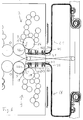
- both receiving devices 41, 42 move in the direction of an arrow F. or G into a position A (FIG. 3) or B below the forme cylinder 4 or above the forme cylinder 5, from which the printing formes 26 or 29 are raised in the direction of the forme cylinder 4 or lowered in the direction of the forme cylinder 5 can be.
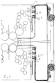
- FIG. 4 shows how the printing form 26 is raised below the forme cylinder 4 in such a way that its head-side hook-in bend 47 is received by the clamping channel 16 of the forme cylinder 4.
- the printing form 29 is lowered downwards by the receiving device 42, ie by its suction pads 45, to such an extent that the foot-side hooking fold 48 of the printing form 29 is received by the clamping channel 18 of the forme cylinder 5.
- the front pressure or guide rollers 46a on the holding devices 41, 42 each serve to press the head or foot part of the printing form 26 or the printing form 29 into the tensioning channel 16 or the tensioning channel 18.
- each of the front and middle suction pads 45 from the pressure plate 26 and 29 released and withdrawn.
- the rear suction pads 45c stay with reduced suction power on the pressure plates 26, 29 so that they too At the beginning of the pulling process, stay taut on the forme cylinders 4 or 5.
- the printing formes 26, 29 By turning the forme cylinders 4, 5, the printing formes 26, 29 in the direction of rotation C or C 'against the holding force H or H of the suction pad 45 and preferably with simultaneous pressing by the respective front pressing or guide roller 46a onto the forme cylinder 4 or 5.
- the receiving devices 41, 42 From the position of the receiving devices 41, 42 shown in FIG. 1, which is also suitable, for example, as a "parking position", the receiving devices 41, 42 move into the position shown in FIG. 5 by the printing plates 26 and 29 again from the lateral surfaces to remove the forme cylinder 4 or 5.
- the forme cylinders 4 and 5 are rotated into their respective unclamping positions by the angles ⁇ and ⁇ '(direction of rotation D and D, respectively ).
- the sequence of the receiving of the printing form 26 by the receiving device 41 from the upper printing unit 2 by the receiving device 41 differs from the receiving of the printing form 29 by the receiving device 42 from the lower printing unit 3.
- the overhead printing unit 2 runs when the forme cylinder 4 in the Unloading position has arrived, first the front of the pressing or Guide rollers 46, d. H. the roller 46a, and presses on the on the Forme cylinder circumference printing form 26. After the pressure roller 46a the printing plate 26 is placed, the rear plate clamping device, ie for example in the case of the printing form 26 that contained in the clamping channel 17 Clamping device for the rear hooking fold 47, opened. Through the The inherent rigidity of the printing form 26 springs its foot end out of the tensioning device the clamping channel 17. By turning the forme cylinder 4 in the direction of Arrow D, the printing form 26 is unwound from the circumference of the forme cylinder 4.
- the unwinding process corresponding to the above Receiving device 41 located piece of the printing form 26 the middle and the rear of the pressure or guide rollers 46, d. H. the pressure rollers 46b and 46c moved out so that the printing form 26 tangential to the circumference of the Forme cylinder 4 placed in a horizontal position on the receiving device 41 and is put off.
- the printing form 26 is then completely on the Cradle 41 on when the front plate chuck that the Printing form 26 has fixed in the clamping channel 17, the position of the rear Plate clamping device, which has fixed the printing form in the clamping channel 16, has taken.
- Printing form 29 can be when the forme cylinder 5 is rotated by the angle of rotation ⁇ ' has been so that the tensioning channel 19 of the front pressure roller 46a Opposite the receiving device 42, remove from the forme cylinder 5: initially only the pressure roller 46a is directed towards the tensioning channel 19 extended until it rests on the circumference of the forme cylinder 5. The remaining Pressure or guide rollers 46b and 46c remain retracted. after the Pressure roller 46a is employed on the forme cylinder 5, the Plate clamping device in the clamping channel 19 opened. Through the The rigidity of the pressure plate 29 springs its head part out of the Plate clamping device in the clamping channel 19 out.
- the printing form 29 is moved into the position shown in FIG. 8 transported in which the suction pads 45 and the pressure or guide rollers 46a to 46c are extended into the unloading position in order to attach the printing forme 26 to a Dispose of disposal device 50.
- the receiving device 41 moves back towards E.
- the receiving device 42 gives the printing form 29 to a disposal device 51 corresponding to disposal device 50, wherein after receiving the printing form 29 from the support plate 49 in the direction E 'drives.
- the disposal devices 50, 51 each have a slope 52, via which the printing form 26 or 29 can slide down into it.
- receiving devices 41, 42 the printing forms 26, 29 take over from automatic printing form feed devices 53, 54, as they are already known from DE 44 22 265 A1.
- the Printing forms for example printing forms 26 and 29, illustrated and with the Foot part hung up in register in the transport devices 53, 54.
- the Printing forms For example, four printing plates can be arranged side by side.
- the printing forms become corresponding printing units 2, 3 transported, where they are parallel to Printing unit 2, 3 are provided.
- the printing forms 26, 29 provided are there, as shown in FIG. 9, by the receiving devices 41, 42 added.
- Retracting devices can also be used as transport devices Use to pull in the beginning of a substrate. Such Retraction devices are known for example from DE 43 18 299 A1.
- one Conveyor belt can also be an endless chain or an endless conveyor belt 55, 56, as shown in FIG. 10.
- the conveyor chains 55, 56 are moved over pulleys 57 to 64 and by motors 65, 66 driven, which are preferably electronically synchronized with each other.
- motors 65, 66 driven which are preferably electronically synchronized with each other.
- Synchronization can also serve a synchronous shaft.
- the conveyor chains or Conveyor belts 37, 38, 55, 56 can also have a common mechanical Have drive.
- the invention provides a transport system 24 with conveying means 25, 28 created, each a conveyor chain or a conveyor belt 37, 38, 55, 56 has and for the transport of printing forms 26, 27, 29, 30 from Printing form stores 43, 44 to form cylinders 4, 5.
- suction pads 45 and pressure or guide rollers 46 become the printing formes 26, 27, 29, 30 clamped directly from the conveyor chains 37, 38 to the forme cylinders 4, 5 and, after they have been printed, also from the forme cylinders 4, 5 be removed again.
- the conveyor chains 37, 38 In order to convey the printing forms 26, 27, 29, 30 from the printing form stores 43, 44 and to transport used printing plates back to the disposal devices 50, 51, the conveyor chains 37, 38 must be stopped in four different positions according to the embodiment shown in FIGS. 1 to 9 , which are each represented by positions L, M, N and O or positions L , M , N and O of the beginning of the conveyor chain 37 or of the conveyor chain 38, which is connected to the receiving devices 41, 42.
- positions L, M, N and O or L , M , N and O there are sensors, for example electrical or optical sensors, which deliver a signal to a control device controlling the drive of the conveyor chains 37, 38 when the conveyor chains 37, 38 have the respective positions L, M, N and O or L , M , N and O reached so that they are stopped there according to the program sequence.
- Positions L, M, N and O and L, respectively , M , N and O can also be detected by pneumatically controlled stops. The same applies to the endless conveyor chains or conveyor belts 55, 56 (FIG. 10).
Landscapes
- Discharge By Other Means (AREA)
- Separation, Sorting, Adjustment, Or Bending Of Sheets To Be Conveyed (AREA)
Applications Claiming Priority (2)
| Application Number | Priority Date | Filing Date | Title |
|---|---|---|---|
| DE19804106A DE19804106C2 (de) | 1998-02-03 | 1998-02-03 | Transport- und Montagesystem sowie Verfahren zum Befördern von Druckformen |
| DE19804106 | 1998-02-03 |
Publications (3)
| Publication Number | Publication Date |
|---|---|
| EP0933208A2 true EP0933208A2 (fr) | 1999-08-04 |
| EP0933208A3 EP0933208A3 (fr) | 2000-03-29 |
| EP0933208B1 EP0933208B1 (fr) | 2002-10-16 |
Family
ID=7856450
Family Applications (1)
| Application Number | Title | Priority Date | Filing Date |
|---|---|---|---|
| EP99101829A Expired - Lifetime EP0933208B1 (fr) | 1998-02-03 | 1999-01-28 | Système de transport et procédé pour transporter des formes imprimantes |
Country Status (2)
| Country | Link |
|---|---|
| EP (1) | EP0933208B1 (fr) |
| DE (2) | DE19804106C2 (fr) |
Cited By (11)
| Publication number | Priority date | Publication date | Assignee | Title |
|---|---|---|---|---|
| EP1084836A1 (fr) * | 1999-09-14 | 2001-03-21 | Komori Corporation | Dispositif pour introduire des plaques dans une machine à imprimer rotative |
| EP1084834A3 (fr) * | 1999-09-14 | 2002-01-30 | Komori Corporation | Dispositif pour changer des plaques d'impression dans une presse rotative |
| WO2004085158A3 (fr) * | 2003-03-28 | 2005-06-02 | Koenig & Bauer Ag | Dispositif et procede de stockage d'au moins deux blanchets evacues successivement du meme cylindre d'une presse |
| WO2007135155A3 (fr) * | 2006-05-23 | 2008-01-10 | Koenig & Bauer Ag | Dispositifs disposés dans un groupe d'impression d'une presse rotative |
| DE102006032201A1 (de) * | 2006-07-12 | 2008-01-17 | Koenig & Bauer Aktiengesellschaft | Handhabungseinrichtung zum Handhaben von Druckplatten bei einer Druckmaschine |
| DE102007030174B3 (de) * | 2007-06-27 | 2008-10-23 | Koenig & Bauer Aktiengesellschaft | Verfahren zum Montieren einer biegsamen Druckform auf einem Formzylinder einer Rotationsdruckmaschine |
| EP2172341A1 (fr) * | 2008-10-01 | 2010-04-07 | manroland AG | Presse rotative |
| CN101448644B (zh) * | 2006-05-23 | 2011-06-08 | 柯尼格及包尔公开股份有限公司 | 轮转印刷机印刷机组中的组合装置 |
| WO2012045494A1 (fr) * | 2010-10-07 | 2012-04-12 | Koenig & Bauer Aktiengesellschaft | Système de transport et système de changement de clichés dans une unité d'impression, ainsi que système logistique dans une imprimerie |
| CN101973156B (zh) * | 2006-05-23 | 2012-09-05 | 柯尼格及包尔公开股份有限公司 | 轮转印刷机印刷机组中的组合装置 |
| DE102010042111B4 (de) * | 2010-10-07 | 2015-03-26 | Koenig & Bauer Aktiengesellschaft | Druckformwechselsystem einer Druckeinheit sowie Logistiksytem einer Druckerei umfassend ein Druckformwechselsystem |
Families Citing this family (14)
| Publication number | Priority date | Publication date | Assignee | Title |
|---|---|---|---|---|
| DE10220424A1 (de) * | 2001-12-11 | 2003-06-18 | Swisslog Telelift Gmbh | Verfahren und Vorrichtung zur automatischen Druckplattenübergabe |
| DE10314344B3 (de) | 2003-03-28 | 2004-08-26 | Koenig & Bauer Ag | Vorrichtung zum Speichern eines einem Zylinder einer Druckmaschine zuzuführenden Aufzugs |
| DE102006051219A1 (de) | 2006-01-31 | 2007-08-09 | Koenig & Bauer Aktiengesellschaft | Druckeinheit mit mehreren Druckwerken |
| DE202006020588U1 (de) | 2006-12-01 | 2009-02-19 | Koenig & Bauer Aktiengesellschaft | Neun-Zylinder-Satellitendruckeinheit und ein Druckturm |
| ATE523339T1 (de) | 2006-12-01 | 2011-09-15 | Koenig & Bauer Ag | Verfahren zum betreiben einer druckeinheit mit mindestens einem druckwerk |
| DE102007024607A1 (de) * | 2007-05-25 | 2008-11-27 | Manroland Ag | Verfahren zur Handhabung von Druckplatten sowie Rollendruckmaschine |
| DE102007024608A1 (de) * | 2007-05-25 | 2008-11-27 | Manroland Ag | Verfahren zur Handhabung von Druckplatten |
| DE102008045679A1 (de) * | 2008-04-29 | 2009-11-05 | Manroland Ag | Rollendruckmaschine, Verfahren zur Handhabung von Druckplatten an einer Rollendruckmaschine und Verfahren zum Betreiben einer Rollendruckmaschine |
| DE102013216664B4 (de) * | 2013-08-22 | 2017-05-18 | Koenig & Bauer Ag | Verfahren zur Durchführung eines Druckformwechsels sowie Druckmaschinen mit einem Druckturm und einer vertikalbeweglichen Speichereinrichtung |
| EP3036106B1 (fr) | 2013-08-22 | 2019-05-01 | Koenig & Bauer AG | Procédé de changement de clichés et presses à imprimer dotées d'une tour d'impression et d'un dispositif de stockage à mobilité verticale |
| DE102013216665A1 (de) * | 2013-08-22 | 2015-02-26 | Koenig & Bauer Aktiengesellschaft | Verfahren zum Fördern von Druckformen beim Druckformwechsel sowie Druckmaschine mit einem Druckturm und einer vertikalbeweglichen Speichereinrichtung |
| DE102013216661A1 (de) * | 2013-08-22 | 2015-02-26 | Koenig & Bauer Aktiengesellschaft | Verfahren zum Fördern von Druckformen beim Druckformwechsel sowie Druckmaschine mit einem Druckturm und einer vertikalbeweglichen Speichereinrichtung |
| DE102013216662B4 (de) * | 2013-08-22 | 2017-06-14 | Koenig & Bauer Ag | Verfahren zum Fördern von Druckformen beim Druckformwechsel sowie Druckmaschinen mit einem Druckturm und einer vertikalbeweglichen Speichereinrichtung |
| CN105473337B (zh) | 2013-08-22 | 2017-03-08 | 柯尼格及包尔公开股份有限公司 | 用于在更换印版时给送印版的方法以及具有印刷塔和能够沿竖向运动的储存装置的印刷机 |
Family Cites Families (10)
| Publication number | Priority date | Publication date | Assignee | Title |
|---|---|---|---|---|
| CH610241A5 (fr) * | 1977-02-07 | 1979-04-12 | Sisenca Sa | |
| JPS6262762A (ja) * | 1985-09-12 | 1987-03-19 | Tokyo Kikai Seisakusho:Kk | 新聞印刷における生産工程管理方式 |
| JPS62174157A (ja) * | 1986-01-29 | 1987-07-30 | Mitsubishi Heavy Ind Ltd | 多数枚の紙に孔をあけるパンチの穿孔深さ調節装置 |
| DE3614554A1 (de) * | 1986-04-29 | 1987-11-05 | Harald Gehle | Verfahren zum montieren von klischees auf druckzylindern sowie druckwerk |
| JPH0289646A (ja) * | 1988-09-27 | 1990-03-29 | Isowa Ind Co | 印刷シリンダー及び印版交換装置 |
| JPH0679542U (ja) * | 1993-04-16 | 1994-11-08 | 株式会社イソワ | 印刷装置の印版交換補助装置 |
| DE4318299A1 (de) * | 1993-06-02 | 1994-12-08 | Roland Man Druckmasch | Einziehvorrichtung und Verfahren zum Einzug von Materialbahnen in eine Druckmaschine |
| DE4424931C2 (de) * | 1994-01-17 | 1996-08-14 | Koenig & Bauer Albert Ag | Vorrichtung zur Montage, Demontage und Transport von leicht biegbaren, bogenförmigen Gegenständen mit Einhängeabkantungen |
| DE19531024B4 (de) * | 1994-11-16 | 2005-01-27 | Kabushiki Kaisha Tokyo Kikai Seisakusho | Vorrichtung und Verfahren zum Anbringen einer Druckplatte auf einem Plattenzylinder einer Rotationsdruckpresse |
| DE4442265A1 (de) * | 1994-11-28 | 1996-05-30 | Roland Man Druckmasch | Transportsystem zum Transport von Druckformen |
-
1998
- 1998-02-03 DE DE19804106A patent/DE19804106C2/de not_active Expired - Fee Related
-
1999
- 1999-01-28 DE DE59903068T patent/DE59903068D1/de not_active Expired - Fee Related
- 1999-01-28 EP EP99101829A patent/EP0933208B1/fr not_active Expired - Lifetime
Cited By (22)
| Publication number | Priority date | Publication date | Assignee | Title |
|---|---|---|---|---|
| EP1084834A3 (fr) * | 1999-09-14 | 2002-01-30 | Komori Corporation | Dispositif pour changer des plaques d'impression dans une presse rotative |
| US6526887B1 (en) | 1999-09-14 | 2003-03-04 | Komori Corporation | Plate inserting apparatus in rotary printing press |
| EP1595701A2 (fr) | 1999-09-14 | 2005-11-16 | Komori Corporation | Dispositif pour introduire des plaques dans une machine à imprimer rotative |
| EP1595701A3 (fr) * | 1999-09-14 | 2007-09-26 | Komori Corporation | Dispositif pour introduire des plaques dans une machine à imprimer rotative |
| EP1084836A1 (fr) * | 1999-09-14 | 2001-03-21 | Komori Corporation | Dispositif pour introduire des plaques dans une machine à imprimer rotative |
| US7530309B2 (en) | 2003-03-28 | 2009-05-12 | Koenig & Bauer Aktiengesellschaft | Device for storing at least two dressings that are drawn off from the same cylinder of a printing machine one after another |
| WO2004085158A3 (fr) * | 2003-03-28 | 2005-06-02 | Koenig & Bauer Ag | Dispositif et procede de stockage d'au moins deux blanchets evacues successivement du meme cylindre d'une presse |
| EP1862306A1 (fr) * | 2003-03-28 | 2007-12-05 | Koenig & Bauer Aktiengesellschaft | Procédé pour décharger un blanchet d'un cylindre d'une presse |
| US7806052B2 (en) | 2003-03-28 | 2010-10-05 | Koenig & Bauer Aktiengesellschaft | Printing forme magazine with a receiving arrangement for receiving a plurality of printing formes to be mounted on a forme cylinder of a printing press |
| EP1938986A1 (fr) * | 2003-03-28 | 2008-07-02 | Koenig & Bauer AG | Procédé pour stocker et pour décharger un revêtement d'un cylindre d'une presse |
| US8006617B2 (en) | 2006-05-23 | 2011-08-30 | Koenig & Bauer Aktiengesellschaft | Assemblies in a printing couple of a rotary printing press |
| CN101448644B (zh) * | 2006-05-23 | 2011-06-08 | 柯尼格及包尔公开股份有限公司 | 轮转印刷机印刷机组中的组合装置 |
| WO2007135155A3 (fr) * | 2006-05-23 | 2008-01-10 | Koenig & Bauer Ag | Dispositifs disposés dans un groupe d'impression d'une presse rotative |
| CN101973156B (zh) * | 2006-05-23 | 2012-09-05 | 柯尼格及包尔公开股份有限公司 | 轮转印刷机印刷机组中的组合装置 |
| DE102006032201A1 (de) * | 2006-07-12 | 2008-01-17 | Koenig & Bauer Aktiengesellschaft | Handhabungseinrichtung zum Handhaben von Druckplatten bei einer Druckmaschine |
| DE102006032201B4 (de) * | 2006-07-12 | 2013-07-18 | Koenig & Bauer Aktiengesellschaft | Handhabungseinrichtung zum Handhaben von Druckplatten bei einer Druckmaschine |
| DE102007030174B3 (de) * | 2007-06-27 | 2008-10-23 | Koenig & Bauer Aktiengesellschaft | Verfahren zum Montieren einer biegsamen Druckform auf einem Formzylinder einer Rotationsdruckmaschine |
| EP2172341A1 (fr) * | 2008-10-01 | 2010-04-07 | manroland AG | Presse rotative |
| WO2012045494A1 (fr) * | 2010-10-07 | 2012-04-12 | Koenig & Bauer Aktiengesellschaft | Système de transport et système de changement de clichés dans une unité d'impression, ainsi que système logistique dans une imprimerie |
| CN103260885A (zh) * | 2010-10-07 | 2013-08-21 | 柯尼格及包尔公开股份有限公司 | 印刷单元中的运输系统和印版更换系统以及印刷厂中的后勤系统 |
| CN103260885B (zh) * | 2010-10-07 | 2014-10-15 | 柯尼格及包尔公开股份有限公司 | 具有运输系统的印刷单元以及印刷厂中的后勤系统 |
| DE102010042111B4 (de) * | 2010-10-07 | 2015-03-26 | Koenig & Bauer Aktiengesellschaft | Druckformwechselsystem einer Druckeinheit sowie Logistiksytem einer Druckerei umfassend ein Druckformwechselsystem |
Also Published As
| Publication number | Publication date |
|---|---|
| DE59903068D1 (de) | 2002-11-21 |
| DE19804106A1 (de) | 1999-08-19 |
| DE19804106C2 (de) | 2002-10-31 |
| EP0933208A3 (fr) | 2000-03-29 |
| EP0933208B1 (fr) | 2002-10-16 |
Similar Documents
| Publication | Publication Date | Title |
|---|---|---|
| EP0933208B1 (fr) | Système de transport et procédé pour transporter des formes imprimantes | |
| EP0933206B1 (fr) | Procédé et dispositifs pour amener et/ou enlever automatiquement des plaques d'impression vers le/du cylindre porte-plaque d'une machine à imprimer | |
| DE4140413C2 (de) | Vorrichtung zum Wechseln von Druckplatten bei Offsetdruckmaschinen | |
| DE102004037253B4 (de) | Sleevewechselsystem | |
| EP2222472A1 (fr) | Unité de pelliculage modulaire | |
| DE69022822T2 (de) | Platteneinbringungseinrichtung für Druckpressen. | |
| DE19616322B4 (de) | Vertikale Klebepresse | |
| DE4424903C2 (de) | Vorrichtung zur Montage, Demontage und Transport von leicht biegbaren, bogenförmigen Gegenständen mit Einhängeabkantungen | |
| EP2552697A1 (fr) | Système de transport et système de changement de clichés dans une unité d'impression, ainsi que système logistique dans une imprimerie | |
| DE102010042117B4 (de) | Druckformwechselsystem einer Druckeinheit sowie Verfahren zum Aufbringen einer oder mehrerer Druckformen auf einem Formzylinder der Druckeinheit | |
| DE69303916T2 (de) | Vorrichtung zum Wechseln von Druckplatten in einer Druckmaschine | |
| EP0271800B1 (fr) | Convoyeur, en particulier pour des imprimés pliés | |
| EP3036106A1 (fr) | Procédé de changement de clichés et presses à imprimer dotées d'une tour d'impression et d'un dispositif de stockage à mobilité verticale | |
| DE102010042111B4 (de) | Druckformwechselsystem einer Druckeinheit sowie Logistiksytem einer Druckerei umfassend ein Druckformwechselsystem | |
| DE3308069A1 (de) | Vorrichtung zum zusammenfuehren von teilbahnen ueber umlenkwalzen in eine gemeinsame ebene | |
| DE102008005798A1 (de) | Druckmaschine mit einer Vorrichtung zum Wechseln von Druckplatten | |
| DE102010042100A1 (de) | Transportsystem in einer Druckeinheit für den Transport mindestens einer neu auf einem Formzylinder der Druckeinheit aufzubringenden Druckform sowie Druckeinheit mit einem Transportsystem | |
| DE4220011C2 (de) | Verfahren und Einrichtung zum automatischen Ein- und/oder Auszug von flexiblen Druckplatten | |
| DE102013216664B4 (de) | Verfahren zur Durchführung eines Druckformwechsels sowie Druckmaschinen mit einem Druckturm und einer vertikalbeweglichen Speichereinrichtung | |
| DE102012202533B3 (de) | Verfahren, Vorrichtung und System zur Bereitstellung eines Satzes von in einer Druckmaschine neu aufzulegender Druckformen | |
| DE102010042094B4 (de) | Trägerelement zur manuellen und/oder automatischen Beförderung mehrerer Druckformen, Transportsystem in einer Druckerei mit einem Trägerelement sowie Verwendung eines Trägerelementes in einem Transportsystem einer Druckerei | |
| DE2519662C2 (de) | Vorrichtung zum Einziehen der Werkstoffbahn in Rotationsdruckmaschinen | |
| EP0054973B1 (fr) | Dispositif de fabrication de rouleaux de bandes formées à partir de feuilles souples imbriqueés | |
| DE102013216662B4 (de) | Verfahren zum Fördern von Druckformen beim Druckformwechsel sowie Druckmaschinen mit einem Druckturm und einer vertikalbeweglichen Speichereinrichtung | |
| DE102010042114B4 (de) | Druckformwechselsystem einer Druckeinheit sowie Logistiksystem einer Druckerei umfassend ein Druckformwechselsystem |
Legal Events
| Date | Code | Title | Description |
|---|---|---|---|
| PUAI | Public reference made under article 153(3) epc to a published international application that has entered the european phase |
Free format text: ORIGINAL CODE: 0009012 |
|
| AK | Designated contracting states |
Kind code of ref document: A2 Designated state(s): CH DE FR GB LI |
|
| AX | Request for extension of the european patent |
Free format text: AL;LT;LV;MK;RO;SI |
|
| PUAL | Search report despatched |
Free format text: ORIGINAL CODE: 0009013 |
|
| AK | Designated contracting states |
Kind code of ref document: A3 Designated state(s): AT BE CH CY DE DK ES FI FR GB GR IE IT LI LU MC NL PT SE |
|
| AX | Request for extension of the european patent |
Free format text: AL;LT;LV;MK;RO;SI |
|
| 17P | Request for examination filed |
Effective date: 20000802 |
|
| 17Q | First examination report despatched |
Effective date: 20001019 |
|
| AKX | Designation fees paid |
Free format text: CH DE FR GB LI |
|
| GRAG | Despatch of communication of intention to grant |
Free format text: ORIGINAL CODE: EPIDOS AGRA |
|
| GRAG | Despatch of communication of intention to grant |
Free format text: ORIGINAL CODE: EPIDOS AGRA |
|
| GRAG | Despatch of communication of intention to grant |
Free format text: ORIGINAL CODE: EPIDOS AGRA |
|
| GRAH | Despatch of communication of intention to grant a patent |
Free format text: ORIGINAL CODE: EPIDOS IGRA |
|
| GRAH | Despatch of communication of intention to grant a patent |
Free format text: ORIGINAL CODE: EPIDOS IGRA |
|
| GRAA | (expected) grant |
Free format text: ORIGINAL CODE: 0009210 |
|
| AK | Designated contracting states |
Kind code of ref document: B1 Designated state(s): CH DE FR GB LI |
|
| REG | Reference to a national code |
Ref country code: GB Ref legal event code: FG4D Free format text: NOT ENGLISH |
|
| REG | Reference to a national code |
Ref country code: CH Ref legal event code: NV Representative=s name: E. BLUM & CO. PATENTANWAELTE Ref country code: CH Ref legal event code: EP |
|
| REF | Corresponds to: |
Ref document number: 59903068 Country of ref document: DE Date of ref document: 20021121 |
|
| GBT | Gb: translation of ep patent filed (gb section 77(6)(a)/1977) |
Effective date: 20030205 |
|
| ET | Fr: translation filed | ||
| PLBE | No opposition filed within time limit |
Free format text: ORIGINAL CODE: 0009261 |
|
| STAA | Information on the status of an ep patent application or granted ep patent |
Free format text: STATUS: NO OPPOSITION FILED WITHIN TIME LIMIT |
|
| 26N | No opposition filed |
Effective date: 20030717 |
|
| REG | Reference to a national code |
Ref country code: CH Ref legal event code: PFA Owner name: MAN ROLAND DRUCKMASCHINEN AG Free format text: MAN ROLAND DRUCKMASCHINEN AG#POSTFACH 10 12 64#63012 OFFENBACH (DE) -TRANSFER TO- MAN ROLAND DRUCKMASCHINEN AG#POSTFACH 10 12 64#63012 OFFENBACH (DE) |
|
| PGFP | Annual fee paid to national office [announced via postgrant information from national office to epo] |
Ref country code: CH Payment date: 20080115 Year of fee payment: 10 |
|
| PGFP | Annual fee paid to national office [announced via postgrant information from national office to epo] |
Ref country code: GB Payment date: 20080124 Year of fee payment: 10 Ref country code: DE Payment date: 20080122 Year of fee payment: 10 |
|
| PGFP | Annual fee paid to national office [announced via postgrant information from national office to epo] |
Ref country code: FR Payment date: 20080111 Year of fee payment: 10 |
|
| REG | Reference to a national code |
Ref country code: CH Ref legal event code: PFA Owner name: MANROLAND AG Free format text: MAN ROLAND DRUCKMASCHINEN AG#POSTFACH 10 12 64#63012 OFFENBACH (DE) -TRANSFER TO- MANROLAND AG#MUEHLHEIMER STRA?E 341#63075 OFFENBACH (DE) |
|
| REG | Reference to a national code |
Ref country code: CH Ref legal event code: PL |
|
| GBPC | Gb: european patent ceased through non-payment of renewal fee |
Effective date: 20090128 |
|
| PG25 | Lapsed in a contracting state [announced via postgrant information from national office to epo] |
Ref country code: LI Free format text: LAPSE BECAUSE OF NON-PAYMENT OF DUE FEES Effective date: 20090131 Ref country code: DE Free format text: LAPSE BECAUSE OF NON-PAYMENT OF DUE FEES Effective date: 20090801 Ref country code: CH Free format text: LAPSE BECAUSE OF NON-PAYMENT OF DUE FEES Effective date: 20090131 |
|
| REG | Reference to a national code |
Ref country code: FR Ref legal event code: ST Effective date: 20091030 |
|
| PG25 | Lapsed in a contracting state [announced via postgrant information from national office to epo] |
Ref country code: GB Free format text: LAPSE BECAUSE OF NON-PAYMENT OF DUE FEES Effective date: 20090128 |
|
| PG25 | Lapsed in a contracting state [announced via postgrant information from national office to epo] |
Ref country code: FR Free format text: LAPSE BECAUSE OF NON-PAYMENT OF DUE FEES Effective date: 20090202 |