EP0933260A2 - Citerne pour recevoir des liquides - Google Patents
Citerne pour recevoir des liquides Download PDFInfo
- Publication number
- EP0933260A2 EP0933260A2 EP19990101899 EP99101899A EP0933260A2 EP 0933260 A2 EP0933260 A2 EP 0933260A2 EP 19990101899 EP19990101899 EP 19990101899 EP 99101899 A EP99101899 A EP 99101899A EP 0933260 A2 EP0933260 A2 EP 0933260A2
- Authority
- EP
- European Patent Office
- Prior art keywords
- tank
- coupling element
- plug
- socket
- tank according
- Prior art date
- Legal status (The legal status is an assumption and is not a legal conclusion. Google has not performed a legal analysis and makes no representation as to the accuracy of the status listed.)
- Withdrawn
Links
- 239000007788 liquid Substances 0.000 title claims abstract description 29
- 230000008878 coupling Effects 0.000 claims abstract description 30
- 238000010168 coupling process Methods 0.000 claims abstract description 30
- 238000005859 coupling reaction Methods 0.000 claims abstract description 30
- 239000013505 freshwater Substances 0.000 claims description 45
- 239000002351 wastewater Substances 0.000 claims description 45
- XLYOFNOQVPJJNP-UHFFFAOYSA-N water Substances O XLYOFNOQVPJJNP-UHFFFAOYSA-N 0.000 claims description 18
- 238000007789 sealing Methods 0.000 claims description 4
- 239000000523 sample Substances 0.000 claims 1
- 238000009423 ventilation Methods 0.000 description 4
- 238000004519 manufacturing process Methods 0.000 description 2
- 239000010865 sewage Substances 0.000 description 2
- 239000004698 Polyethylene Substances 0.000 description 1
- 239000011324 bead Substances 0.000 description 1
- 230000005540 biological transmission Effects 0.000 description 1
- 230000000903 blocking effect Effects 0.000 description 1
- 239000004020 conductor Substances 0.000 description 1
- 239000013013 elastic material Substances 0.000 description 1
- 230000005611 electricity Effects 0.000 description 1
- 239000000945 filler Substances 0.000 description 1
- 238000003780 insertion Methods 0.000 description 1
- 230000037431 insertion Effects 0.000 description 1
- 238000000034 method Methods 0.000 description 1
- -1 polyethylene Polymers 0.000 description 1
- 229920000573 polyethylene Polymers 0.000 description 1
- 238000003825 pressing Methods 0.000 description 1
- 238000005245 sintering Methods 0.000 description 1
Images


Classifications
-
- B—PERFORMING OPERATIONS; TRANSPORTING
- B60—VEHICLES IN GENERAL
- B60R—VEHICLES, VEHICLE FITTINGS, OR VEHICLE PARTS, NOT OTHERWISE PROVIDED FOR
- B60R15/00—Arrangements or adaptations of sanitation devices
Definitions
- the invention relates to a tank for holding liquid according to the preamble of claim 1.
- Fresh and waste water tanks are used in numerous areas. Especially Such tanks are often used in caravans or caravans. They exist nowadays usually made of food-safe, recyclable polyethylene and are manufactured using the rotary sintering process.
- a disadvantage of most wastewater and fresh water tanks is that they do not display a fill level so that the owner of these tanks never knows exactly how much Liquid they still contain.
- a waste water tank for campers is already known Level can be checked from the inside of the camper and also does not overflow (DE-OS 26 50 315).
- This waste water tank has one Connection piece for the airtight connection of a waste water pipe of the camping car and a vent pipe with a vent. The vent opening protrudes here of the ventilation pipe at a distance from the upper edge of the waste water tank into the waste water tank.
- a water tank for fresh water in caravans is known, with a closable opening for the passage of a riser pipe is provided (DE-GM 84 16 257.0).
- This water tank has a further implementation for one Dirty water pipe on, the end of the dirty water pipe with a flexible Bladder is connected liquid-tight.
- a filler neck is provided which can be closed with a slide (DE-GM 89 12 117).
- slide closure is not a plug connection.
- a waste water tank which has two coupling elements, one of which the one coupling element can be connected to a coupling element of a carrier can while the other coupling element in connection with an outlet adapter stands (GB 2 310 244).
- a plug connection between the tank and a liquid hose is not provided here.
- a wastewater tank for the wastewater from campers etc. is also known, the one connecting piece for the airtight connection of a sewage pipe of a camping car and has a ventilation pipe with a ventilation opening (DE 26 50 315). However, there is between a hose and this waste water tank no plug connection provided.
- a flexible hose which has at both ends a coupling element is provided (GB 2 271 127).
- This is a coupling element inserted into a sewer pipe flange, with an O-ring providing a tight seal manufactures.
- the coupling element at the other end of the hose turns into a portable one Toilet connector inserted, which is screwed into the neck of the portable toilet is.
- Hose fittings and components for pressureless systems are also known (DE 34 00 290 C2, DE 34 48 441, DE 42 30 182). However, they show no solutions for the problem of water hoses on water tanks in a simple way to couple.
- a plug-in coupling system is known from German utility model 296 06 472, that is connected to a pump.
- a liquid tank with level indicator is also known, at least contains a closure (DE 44 45 474 A1).
- This closure acts it is a cover which can be attached to the tank and which has at least one fill level measuring rod is provided.
- the invention has for its object to provide a liquid tank that in a simple way from a waste water tank to a fresh water tank and vice versa can be transformed.
- the advantage achieved by the invention is in particular that by simple Connecting elements that are provided at a tank opening, the tank to one Fresh water or waste water tank can be converted.
- Another advantage is that two components, one of which is the Function of a socket and the other has the function of a plug, independently can be produced from the respective concrete tank. With these components not only the parts essential for the water inflow or outflow are provided, but also the parts that are important for a power supply.
- a conventional fresh water tank 1 is shown, which is essentially corresponds to the tank shown in FIG. 4 of DE 44 45 474.
- This fresh water tank has a first cover 2 and a second cover 3, with the second cover 3 with a projection on the top the fresh water tank 1 is screwed.
- the cover 2 is also with a Screwed projection on the top of the fresh water tank 1 and has in In contrast to the cover 3, two openings 4, 5, one of which is an opening 4 serves as a passage for a water hose, while the other opening 5 is a bushing for an electrical cable, via which one in the fresh water tank 1 located pump is supplied with electrical energy.
- the fresh water tank is easy to transport because it has two wheels 6, 7 and a hand strap 8.
- the hand strap 8 can be folded down so that its upper crosspiece 9 comes to rest in the folded state at the height of the wheels 6, 7.
- With 10, 11, 12 are depressions, which can be reached with the hands so that tank 1 is easier to lift or carry.
- Fig. 2a shows how the fresh water tank 1 from a niche 15 of a motor home 16, which was previously closed by a flap 17, 16 is removed.
- Hand strap 8 is folded down.
- the operator 18 grips with his hand 19 in the trough 12 and thus holds the fresh water tank 1.
- Above the cap 3 shows a water hose 20 and an electric cable 21, which with a Pump, not shown, are connected.
- FIG. 2b shows the fresh water tank 1 lying on the floor in front of the motor home 16.
- the operator 18 is taking an insert 22 out of the opening 23 of the tank.
- This insert 22 contains u. a. a water pump shown in Fig. 2b is not visible because it is still in the fresh water tank 1.
- the one on the Projection 24 located lid 3 is removed and then on the The projection 25 is screwed as soon as the insert 22 is removed.
- This insert 22 is put back into the niche 15 of the motor home.
- the opening 23 now screwed to the cover 3 allows that the fresh water tank 1 can now be rolled away by the operator 18. With 24 the projection on which the cover 3 was previously located.
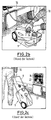
- FIG 3a shows a waste water tank 30 in a recess 31 of the motor home 16. This waste water tank 30 is held by a belt 33.
- the waste water tank 30 To receive waste water 34, the waste water tank 30 is placed under the mobile home 16 placed, as Fig. 3b shows. After a closure, not shown, on the floor the motorhome was opened, the waste water 34 through an opening 35 of the Waste water tanks 30 get into this.
- the waste water tank 30, in contrast to Fresh water tank 1 and an additional handle 36.
- Fig. 3c shows the state that the filled waste water tank 30 by the operator 18 is rolled away.
- FIG. 4 shows a universal tank 40 according to the invention, which is similar Like the fresh water or waste water tanks described above, it has a shape.
- FIG. 4 It has two wheels, of which only one wheel 41 can be seen in FIG. 4. He also has side troughs to better lift it. Of these Troughs only one trough 42 can be seen in FIG. 4.
- a bracket 43 On the bottom of the Universal tanks 40 can be seen a bracket 43, the function of the known Handle 8 corresponds.
- a handle 44 is provided over the visible end of the bracket 43, which is used for the manual transport of the universal tank 40.
- On the top this tank 40 shows a cover 46 and a connection 47.
- This connection 47 is removable from the tank 40 and has an opening 48 and a plurality of fitting openings 49 to 57 provided. These openings 49 to 57 are used for a plug can only be attached in a predetermined way.
- the one in FIG. 4 Not shown plug has as many pins as the connection 47 fitting openings owns. These pins can function as electrical connectors take.
- the universal tank 40 is shown in a side view, wherein he Function of a waste water tank fulfilled.
- the front connection can be seen here 47, which is designed as a waste water connection and therefore only two short level sensors 58, 59 with which it can be determined whether the tank is full.
- a waste water hose 60 is connected to the connection 47 by means of a Plug 61, which with the connection 67 bayonet or in the manner of a Snap lock can be connected.
- the sewage hose 60 as well as a tubular stub 62 of the plug 61 have a relatively large diameter on.
- the tubular nozzle 62 serves as a passage for liquids.
- the pin 61 pins 63, 64 which in corresponding holes of connection 47 fit.
- FIG. 6 shows the same universal tank 40 as FIG. 5, but in one use as a fresh water tank.
- a component 70 is inserted into the tank 40, which has an upper connection 71 and a lower pump area 72.
- the pump area 72 contains a motor pump 73 which is connected to the connection 71 a connecting hose 27 is connected.
- the connection 71 is with provided several sensor rods 74 to 78. With these sensor rods, different Fill levels are recorded.
- a plug With 79, a plug is designated, which has a nozzle 80 with a relatively small diameter having. Several pins 82, 83 ensure that the plug 79 only in one can be connected in a very specific way to the connection 71. At 81 is called a fresh water hose. Parallel to this fresh water hose 81 run several electrical lines.
- connection between the connectors 61, 79 and the associated connections 47, 71 is preferably produced by means of plug or snap closures. It the plug 61 is thus connected to the connection 47 by simply plugging it on, in order to fill the waste water tank with water, for example a caravan comes.
- the water in the fresh water tank can be removed be that the plug 79 with the terminal 71 by simply plugging in is connected.
- the connections 47, 71 can be removed from the tank 40, which has an opening 132 or 133 for this.
- the sockets 62 and 80 are at Waste water and fresh water tanks of different sizes designed to waste water and Freshwater components should not be confused. However, this does not have to be the case based on further embodiments is still shown.
- a special type of plug connection which is similar to the plug connections, that are used in garden hose systems are described in the following 7 to 12 are described.
- FIG. 7 is a first part 68 for the production of a plug or snap connection shown.
- a ring is designated, from the top of a liquid tube 85 protrudes.
- a nozzle 86 protrudes the lamellar elements 87 to 92, 94 are arranged.
- These lamellar Elements 87 to 92 enclose a liquid tube 93, which is an extension of the Represents liquid tube 85 down.
- hose shown are connected, similar to the hose 60 or 81 in the 5 and 6.
- FIG. 8 shows the same part 68 as FIG. 7, but in a longitudinal section. It can be seen here that the ring 84 has a recess 95 which is between an edge region 96 of the ring 84 and the nozzle 86.
- the liquid tubes 85, 93 provide a uniform Pipe that tapers 97 at its lower end.
- This tapered End can be elastic or with an elastic sealing ring (not shown) to be surrounded. It can also contain electrical contacts that are connected to Conductor tracks around or on the tube 85, 93 are connected.
- FIG. 9 shows a second part 100 for the production of a plug-in or snap connection.
- This part which is put into an opening of a tank can consists of a cylinder 101 and a cylinder 101 surrounding this Ring 102.
- a connecting piece 103 protrudes.
- This connector can be connected to a pump, similar to that Port 71 in Fig. 6.
- the second part 100 is shown again in longitudinal section.
- an annular recess 104 is provided in the cylinder 101 into which an annular projection 105 of the ring 102 projects. Between this annular projection 105 and the upper edge 106 of the recess 104 a coil spring 107 is arranged, which presses on the projection 105.
- Another coil spring 108 is provided on the other side of the recess 104, which is 109 is designated.
- Coil springs can also be provided with a uniform spring-elastic element, for example a highly elastic rubber ring.
- a circumferential locking lug 110 to which an annular Projection 111 connects with a conical opening 112 downwards.
- the connecting piece 103 according to FIG. 9 is omitted from FIG. 10. For example, it can by screwing with the recess in the lower region of the cylinder 101 in Connect.
- FIG 11 shows an overall connection consisting of the first part 68 and the second Part 100 is when the two parts 68, 100 are connected together.
- the part 68 can be connected with a hose, while the part 100 into a Opening of a water tank is fitted.
- connection between the two parts 68, 100 is established in such a way that the two parts 68, 100 correspond to one another in the direction of the arrows 130, 131 be moved until they lock together.
- the locking takes place in the way that the hooks 120, 121 engage behind the detent 110. They will be solved both parts 68, 100 in that the ring 102 in the direction of arrow 131 upwards is pushed.
- the parts 68 and 100 shown in FIGS. 8 and 10 additionally have mechanical ones Latching and electrical coupling elements on the individual for clarity because are not shown.
- Mechanical latching elements are understood to mean such elements which also prevent relative rotation between part 68 and part 100 can. Such twisting should be prevented because between the two parts 68 and 100 not only a mechanical but also an electrical one Connection should be made and it could cause problems if electrical connecting wires would be twisted.
- a mechanical catch in the sense described above can be done in a simple manner by that the part has a projection, which in a corresponding recess of the Part 100 intervenes or vice versa. For example, such a place could be the lower one End 97 of part 68 or the edge of part 101 opposite this part be. This area could also be used for the continuation of electrical lines, which would then have to be embedded in the tube 85, for example.
- the depression and the projection associated with it could function as Take over the plug and socket.
- the tight closure of the opening 112 is by an elastic end 97 or ensures a sealing ring arranged on the outside of this end 97.
- the sealing ring can also be located on the projections 111, 112, while the end 97 is inelastic.
- the ring 102 is countered the force of the springs 107, 108 shifted upward, so that the tip 122 of the Projection 105 presses against the lamella-like elements 87, 94. This will the hooks 120, 121 released from the annular projection 110, and the upper one Part 68 can be removed. It is understood that between the outer wall of the liquid tube 85 and the lamella-like elements 87, 94 are sufficient large distance must exist so that the elements 87, 94 from their snap connection can be solved.
- 13 and 14 is a variant of the connecting elements according to FIG. 7 to 12, in which the functions of the elements are interchanged.
- the element 8 is now in an opening of the tank while the element 10 is in a modified form on a hose.
- the plug-on 79 shown in FIG. 6 is very coarse and exaggerated shown large with dashed lines, with the pins 82, 83 omitted are.
- Part 100 is now located in it, specifically in relation to the representation of FIG 10 in a position rotated by 180 degrees.
- the fresh water hose 81 leads for example inside a motorhome.
- connection 71 shown in FIG. 6 is indicated with dashed lines.
- the holes for receiving pins are omitted here.
- Connection 71 and projecting into the tank 40 is that shown in FIG. 8 Part 68, but rotated 180 degrees.
- This part 68 forms - which is not closer is shown - with a pump and with liquid sensors that shown in FIG. 6 Component 70.
- the snap connection shown in FIGS. 13 and 14 can be used for both Fresh water tank as well as a waste water tank are used. It then only the snap connections according to FIGS. 13 and 14 to the Adjusted conditions of Fig. 5 and Fig. 6.
- fresh water tank z. B Several electrical cables can also be integrated into the connector. This Electrical lines are connected to the electrical connections via plug connections connected to the pump in the manner already described above. Vent lines can also be integrated in the plug.
- FIG. 15 shows the component 70 from FIG. 6, which is provided for a fresh water tank is shown again in more detail.
- the motor pump 73 which has an upper flange 200 and a lower flange 201.
- the top connector 71 has a cylindrical body 203, which has a thread 204 is provided. With this thread, the component 70 can be connected to a tank 40 are, the opening 35, 132, 133 provided with a corresponding internal thread is.
- a rubber ring 206 is provided below an end plate 205 rests on a bulge 207. Is on the top of this end plate a connector housing 214.
- a cylindrical connection piece 208 is flanged to the cylindrical body 203 is hollow on the inside and continues downwards by means of a narrower tube 209.
- an internally hollow connection piece 210 is provided, which is connected to the narrow tube 209 via a transparent spout 211.
- the electrical power supply to the motor pump 73 takes place via a cable 212, the one end in a socket 213 of the flange 200 and the other End in body 203 ends.
- the connector housing 214 comprises a total of seven electrical contact pins 215 to 221 and is open on one side. This opening is designated 114. Furthermore it has an inner part 222 and an outer ring 223 surrounding it. The inner part 222 is provided with a recess 224, one at its bottom Has opening 225. This inner part 222 also has one at two locations Notch 226, 227.
- FIG. 16 A perspective view of the upper connector 71 shown in FIG. 16 is shown in FIG.
- FIG. 18 shows a plug 230 for a fresh water tank, which has similarities with the plug-in shown in Fig. 6 and on the in Fig. 15 to 17 shown part 70 can be plugged.
- the fresh water hose is therefore also designated 81, while the nozzle is designated 80.
- the badge 230 is with an elastic hose and corrugated on the outside 231 provided in the fresh water hose 81 and seven electrical lines 232 to 238 run.
- the socket 80 is provided with two elastic rings 239, 240 and on a lower one cylindrical part 241 of the plug 230 arranged.
- the lower cylindrical Part 241 merges into an upper part 242 and forms a lower part with it Shell of the badge 230.
- Part of this lower shell is also a semi-cylindrical part 243, which comprises one half of the hose 231.
- an upper shell which consists of a domed lid 244 and a semi-cylindrical part 245. Will the Stub 80 inserted into the opening 224, due to the rings 239, 240 one Hermetically sealed and the nozzle held in the opening 224.
- this cover 244 and the semi-cylindrical part 245 are again to see.
- This nozzle 80 is in the opening 224 of part 71 (Fig. 16) inserted.
- the guide part 251 is a component of a valve which causes the flow or the blocking of the water flow.
- FIG. 19 shows the same plug 230 as in FIG. 19, but in a view the bottom 241.
- a multiple socket 252 in which the seven pins 215 to 221 (Fig. 16) can be inserted. It also sticks out Guide part 251 from the socket 80, being arranged in a star shape by six Bridges 253 to 258 surround the guide part hold in the middle.
- FIG. 21 Another view of the same part as in FIG. 20 is shown in FIG. 21.
- Man recognizes the semi-cylindrical part 243 that surrounds the hose 231. Furthermore the elastic rings 239, 240 are removed, so that two grooves 260, 261 sees.
- Fig. 22 shows the same object as Fig. 21, but rotated by 180 °, i. H. of the in Fig. 21 upward nozzle 80 now points downwards. This is the view into the interior of the lower shell 241, 242, 243 is released.
- the multiple socket 252 is located near hollow molded parts 262 to 265 from which z. B. the connecting elements 262, 263 can accommodate screws.
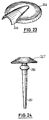
- the domed cover 244, with which the part 241, 242 is connected, is shown in FIG. 23 shown again as a single part.
- FIGS. 19 and 20 show, on a greatly enlarged scale, a valve with the guide part 251, that could already be seen in FIGS. 19 and 20.
- This guide part 251 widened towards the top to a bead 266, which is followed by a valve screen 267.
- the actual valve function is performed by the valve screen 267.
- the guide part The only function of 251 is to keep the valve screen in its horizontal position. If water presses on the valve screen from above or below, it moves in the vertical direction and opens or closes a flow.
- the same tank 40 can be used as a fresh water tank and once used as a waste water tank, the Differentiate coupling elements not only with regard to the pump, but also with regard to the size of the liquid passages 62, 80.
- the connection part 61 does not fit on the connection area 71, as the connector 79 does not fit on the connection area 47.
- FIGS. 15 to 24 Another variant is shown in FIGS. 15 to 24, in which the connecting part or the plug-on 230 for the waste water tank and the fresh water tank is the same and only the connection area 71 connected to the tank 40 is replaced becomes. Even this connection area 71 can in its upper part with the corresponding part of the waste water tank must be identical (see. Fig. 16, 17).
- the motor pump In this case, 73 can be coupled to part 71, which is also for a waste water tank Can be used.
- contact pins 80 to 82 of the plug 230 are in use only a few functions in a waste water tank.
Landscapes
- Health & Medical Sciences (AREA)
- Epidemiology (AREA)
- General Health & Medical Sciences (AREA)
- Public Health (AREA)
- Engineering & Computer Science (AREA)
- Mechanical Engineering (AREA)
- Quick-Acting Or Multi-Walled Pipe Joints (AREA)
Applications Claiming Priority (2)
| Application Number | Priority Date | Filing Date | Title |
|---|---|---|---|
| DE19803512 | 1998-01-30 | ||
| DE1998103512 DE19803512A1 (de) | 1998-01-30 | 1998-01-30 | Tank für die Aufnahme von Flüssigkeit |
Publications (1)
| Publication Number | Publication Date |
|---|---|
| EP0933260A2 true EP0933260A2 (fr) | 1999-08-04 |
Family
ID=7856074
Family Applications (1)
| Application Number | Title | Priority Date | Filing Date |
|---|---|---|---|
| EP19990101899 Withdrawn EP0933260A2 (fr) | 1998-01-30 | 1999-01-29 | Citerne pour recevoir des liquides |
Country Status (2)
| Country | Link |
|---|---|
| EP (1) | EP0933260A2 (fr) |
| DE (1) | DE19803512A1 (fr) |
Cited By (3)
| Publication number | Priority date | Publication date | Assignee | Title |
|---|---|---|---|---|
| DE19945066C1 (de) * | 1999-09-20 | 2001-04-05 | Fusion Kunststoff Gmbh | Wassertank |
| WO2006102871A1 (fr) | 2005-04-01 | 2006-10-05 | Pierre Biglari | Elimination de dechets dans des autocaravanes ou equivalent |
| WO2018037430A1 (fr) * | 2016-08-26 | 2018-03-01 | METALLARTE s.r.l. | Porte pour véhicules de plaisance à poubelle amovible intégrée |
Families Citing this family (3)
| Publication number | Priority date | Publication date | Assignee | Title |
|---|---|---|---|---|
| DE102013009043B4 (de) * | 2013-05-28 | 2025-01-23 | Diehl Aviation Hamburg Gmbh | Wasserversorgungsvorrichtung sowie Verfahren zur Versorgung einer Mischeinrichtung |
| DE102018006973B3 (de) | 2018-09-04 | 2019-12-19 | Herbert Schönmetzler | Vorrichtung zur Ver- und/oder Entsorgung von Flüssigkeiten in Wohnwagen und/oder Wohnmobilen |
| DE102020002557B3 (de) | 2020-04-28 | 2021-10-21 | Herbert Schönmetzler | Tankinstallation zum Befüllen, Lagern oder Entnehmen von Flüssigkeit für mobile Flüssigkeitstanks |
Citations (10)
| Publication number | Priority date | Publication date | Assignee | Title |
|---|---|---|---|---|
| DE2650315A1 (de) | 1976-11-02 | 1978-05-03 | Amtenbrink Paul | Abwasserbehaelter fuer campingwagen |
| DE8416257U1 (de) | 1984-05-29 | 1984-09-06 | Lyding, Peter, 5810 Witten | Wasserbehälter für Frischwasser in Wohnwagen |
| DE8912117U1 (de) | 1989-10-11 | 1990-05-23 | AL-KO Kober AG, 8871 Kötz | Vorrichtung zur Abwasserentsorgung sanitärer Anlagen bei Kraftfahrzeugen, insbesondere Wohnwagen oder dergleichen |
| DE4230182A1 (de) | 1991-09-11 | 1993-03-18 | Reich Kg Regel & Sicherheits | Wasserauslaufsteuerarmatur fuer drucklose wassersysteme |
| GB2271127A (en) | 1992-09-30 | 1994-04-06 | Emlyn Robert Miller | A device for connecting a portable toilet to a waste/sewage disposal system |
| DE3448441C2 (de) | 1984-01-05 | 1996-01-11 | Reich Kg Regel & Sicherheits | Wasserhahn für drucklose Systeme |
| DE4445474A1 (de) | 1994-12-20 | 1996-06-27 | Fusion Kunststoff Gmbh | Flüssigkeitstank mit Füllstandsanzeige |
| DE3400290C2 (de) | 1984-01-05 | 1996-07-11 | Reich Kg Regel & Sicherheits | Schlauchverschraubung an einem Zu- oder Auslaufteil von Komponenten druckloser Wasserversorgungssysteme |
| DE29606472U1 (de) | 1996-04-09 | 1996-07-11 | Cyanamid Agrar GmbH & Co. KG, 55218 Ingelheim | Großgebinde-Mehrwegsystem für Flüssigprodukte, insbesondere für Pflanzenschutzmittel |
| GB2310244A (en) | 1996-02-14 | 1997-08-20 | Superpitch Ltd | Waste water collection and storage system for vehicles |
Family Cites Families (4)
| Publication number | Priority date | Publication date | Assignee | Title |
|---|---|---|---|---|
| DE3410557A1 (de) * | 1984-03-22 | 1985-10-03 | Westfalia-Werke Franz Knöbel & Söhne KG, 4840 Rheda-Wiedenbrück | Fuellvorrichtung fuer einen fuer wasserversorgung von campingfahrzeugen, reisemobilen oder aehnlichen fahrzeugen dienenden tank |
| GB8624621D0 (en) * | 1986-10-14 | 1986-11-19 | Blagden Ind Plc | Fuel tank |
| DE9112492U1 (de) * | 1991-10-08 | 1993-02-04 | Wehalith Heinrich Wenigmann, 5657 Haan | Kunststoffkanister |
| DE4333454A1 (de) * | 1993-04-03 | 1994-10-06 | Fusion Kunststoff Gmbh | Träger-Behälter-Kombination |
-
1998
- 1998-01-30 DE DE1998103512 patent/DE19803512A1/de not_active Withdrawn
-
1999
- 1999-01-29 EP EP19990101899 patent/EP0933260A2/fr not_active Withdrawn
Patent Citations (10)
| Publication number | Priority date | Publication date | Assignee | Title |
|---|---|---|---|---|
| DE2650315A1 (de) | 1976-11-02 | 1978-05-03 | Amtenbrink Paul | Abwasserbehaelter fuer campingwagen |
| DE3448441C2 (de) | 1984-01-05 | 1996-01-11 | Reich Kg Regel & Sicherheits | Wasserhahn für drucklose Systeme |
| DE3400290C2 (de) | 1984-01-05 | 1996-07-11 | Reich Kg Regel & Sicherheits | Schlauchverschraubung an einem Zu- oder Auslaufteil von Komponenten druckloser Wasserversorgungssysteme |
| DE8416257U1 (de) | 1984-05-29 | 1984-09-06 | Lyding, Peter, 5810 Witten | Wasserbehälter für Frischwasser in Wohnwagen |
| DE8912117U1 (de) | 1989-10-11 | 1990-05-23 | AL-KO Kober AG, 8871 Kötz | Vorrichtung zur Abwasserentsorgung sanitärer Anlagen bei Kraftfahrzeugen, insbesondere Wohnwagen oder dergleichen |
| DE4230182A1 (de) | 1991-09-11 | 1993-03-18 | Reich Kg Regel & Sicherheits | Wasserauslaufsteuerarmatur fuer drucklose wassersysteme |
| GB2271127A (en) | 1992-09-30 | 1994-04-06 | Emlyn Robert Miller | A device for connecting a portable toilet to a waste/sewage disposal system |
| DE4445474A1 (de) | 1994-12-20 | 1996-06-27 | Fusion Kunststoff Gmbh | Flüssigkeitstank mit Füllstandsanzeige |
| GB2310244A (en) | 1996-02-14 | 1997-08-20 | Superpitch Ltd | Waste water collection and storage system for vehicles |
| DE29606472U1 (de) | 1996-04-09 | 1996-07-11 | Cyanamid Agrar GmbH & Co. KG, 55218 Ingelheim | Großgebinde-Mehrwegsystem für Flüssigprodukte, insbesondere für Pflanzenschutzmittel |
Cited By (5)
| Publication number | Priority date | Publication date | Assignee | Title |
|---|---|---|---|---|
| DE19945066C1 (de) * | 1999-09-20 | 2001-04-05 | Fusion Kunststoff Gmbh | Wassertank |
| WO2006102871A1 (fr) | 2005-04-01 | 2006-10-05 | Pierre Biglari | Elimination de dechets dans des autocaravanes ou equivalent |
| DE102005014931A1 (de) * | 2005-04-01 | 2006-10-05 | Pierre Biglari | Abfallbeseitigung in Wohnmobilen o. dgl. |
| DE102005014931B4 (de) * | 2005-04-01 | 2007-05-24 | Pierre Biglari | Abfallbeseitigung in Wohnmobilen o. dgl. |
| WO2018037430A1 (fr) * | 2016-08-26 | 2018-03-01 | METALLARTE s.r.l. | Porte pour véhicules de plaisance à poubelle amovible intégrée |
Also Published As
| Publication number | Publication date |
|---|---|
| DE19803512A1 (de) | 1999-08-05 |
Similar Documents
| Publication | Publication Date | Title |
|---|---|---|
| EP2037545B1 (fr) | Prise pour un dispositif de raccordement multipolaire | |
| DE2827847A1 (de) | Steckverbindung, insbesondere fuer sanitaergegenstaende | |
| EP2857733B1 (fr) | Combinaison comportant une pièce de raccordement, un embout de tuyau souple et un écrou | |
| DE4029792A1 (de) | Anordnung zur befestigung einer handbrause | |
| WO2022049129A1 (fr) | Filtre comportant un dispositif de centrage | |
| DE112022003878T5 (de) | Abflussreinigerwerkzeug | |
| EP0873890B1 (fr) | Sous-groupe | |
| DE102012212302C5 (de) | Sanitärarmatur | |
| EP0615922A1 (fr) | Cartouche multiple et assemblage | |
| EP0933260A2 (fr) | Citerne pour recevoir des liquides | |
| DE202007004832U1 (de) | Befestigungsvorrichtung für eine Wasserarmatur | |
| DE1671833A1 (de) | Fuell- und Belueftungsvorrichtung fuer Batterien | |
| DE20102420U1 (de) | Kupplung für die Verbindung eines Anhängers mit einem Kraftfahrzeug | |
| DE10335330A1 (de) | Frischwasser-Zulaufgarnitur für wasserführende Haushaltgeräte | |
| DE3510843C1 (en) | Apparatus for the confusion-free coupling of supply containers containing various liquids to supply container reception devices | |
| DE202006004768U1 (de) | Bajonettverschluss mit Selbstkontaktierung | |
| EP0074034A2 (fr) | Accessoire de montage pour élément à installer dans un réservoir pour eaux usées | |
| DE4445474A1 (de) | Flüssigkeitstank mit Füllstandsanzeige | |
| DE3320492A1 (de) | Tankgeraet | |
| DE19507640C1 (de) | Aufsteckbarer Wasserhahnadapter | |
| DE68906630T2 (de) | Leckfreie kupplungsvorrichtung von zwei behaeltern. | |
| DE2434544C2 (de) | Armatur zum Mischen mindestens zweier Flüssigkeiten | |
| DE202005020263U1 (de) | Mehrfachkupplung für Medienleitungen | |
| WO1991000428A1 (fr) | Pompe a moteur submersible | |
| AT395327B (de) | Anschlussvorrichtung mit einem doppelrohranschluss fuer eine wasserarmatur |
Legal Events
| Date | Code | Title | Description |
|---|---|---|---|
| PUAI | Public reference made under article 153(3) epc to a published international application that has entered the european phase |
Free format text: ORIGINAL CODE: 0009012 |
|
| AK | Designated contracting states |
Kind code of ref document: A2 Designated state(s): AT BE CH CY DE DK ES FI FR GB GR IE IT LI LU MC NL PT SE |
|
| AX | Request for extension of the european patent |
Free format text: AL;LT;LV;MK;RO;SI |
|
| STAA | Information on the status of an ep patent application or granted ep patent |
Free format text: STATUS: THE APPLICATION IS DEEMED TO BE WITHDRAWN |
|
| 18D | Application deemed to be withdrawn |
Effective date: 20010801 |