EP2857733B1 - Combinaison comportant une pièce de raccordement, un embout de tuyau souple et un écrou - Google Patents
Combinaison comportant une pièce de raccordement, un embout de tuyau souple et un écrou Download PDFInfo
- Publication number
- EP2857733B1 EP2857733B1 EP13187120.4A EP13187120A EP2857733B1 EP 2857733 B1 EP2857733 B1 EP 2857733B1 EP 13187120 A EP13187120 A EP 13187120A EP 2857733 B1 EP2857733 B1 EP 2857733B1
- Authority
- EP
- European Patent Office
- Prior art keywords
- nut
- hose
- attachment part
- clamping
- structural element
- Prior art date
- Legal status (The legal status is an assumption and is not a legal conclusion. Google has not performed a legal analysis and makes no representation as to the accuracy of the status listed.)
- Active
Links
Images



Classifications
-
- F—MECHANICAL ENGINEERING; LIGHTING; HEATING; WEAPONS; BLASTING
- F16—ENGINEERING ELEMENTS AND UNITS; GENERAL MEASURES FOR PRODUCING AND MAINTAINING EFFECTIVE FUNCTIONING OF MACHINES OR INSTALLATIONS; THERMAL INSULATION IN GENERAL
- F16L—PIPES; JOINTS OR FITTINGS FOR PIPES; SUPPORTS FOR PIPES, CABLES OR PROTECTIVE TUBING; MEANS FOR THERMAL INSULATION IN GENERAL
- F16L33/00—Arrangements for connecting hoses to rigid members; Rigid hose-connectors, i.e. single members engaging both hoses
- F16L33/22—Arrangements for connecting hoses to rigid members; Rigid hose-connectors, i.e. single members engaging both hoses with means not mentioned in the preceding groups for gripping the hose between inner and outer parts
- F16L33/225—Arrangements for connecting hoses to rigid members; Rigid hose-connectors, i.e. single members engaging both hoses with means not mentioned in the preceding groups for gripping the hose between inner and outer parts a sleeve being movable axially
- F16L33/226—Arrangements for connecting hoses to rigid members; Rigid hose-connectors, i.e. single members engaging both hoses with means not mentioned in the preceding groups for gripping the hose between inner and outer parts a sleeve being movable axially the sleeve being screwed over the hose
-
- F—MECHANICAL ENGINEERING; LIGHTING; HEATING; WEAPONS; BLASTING
- F16—ENGINEERING ELEMENTS AND UNITS; GENERAL MEASURES FOR PRODUCING AND MAINTAINING EFFECTIVE FUNCTIONING OF MACHINES OR INSTALLATIONS; THERMAL INSULATION IN GENERAL
- F16L—PIPES; JOINTS OR FITTINGS FOR PIPES; SUPPORTS FOR PIPES, CABLES OR PROTECTIVE TUBING; MEANS FOR THERMAL INSULATION IN GENERAL
- F16L19/00—Joints in which sealing surfaces are pressed together by means of a member, e.g. a swivel nut, screwed on, or into, one of the joint parts
- F16L19/005—Joints in which sealing surfaces are pressed together by means of a member, e.g. a swivel nut, screwed on, or into, one of the joint parts comprising locking means for the threaded member
-
- B—PERFORMING OPERATIONS; TRANSPORTING
- B67—OPENING, CLOSING OR CLEANING BOTTLES, JARS OR SIMILAR CONTAINERS; LIQUID HANDLING
- B67D—DISPENSING, DELIVERING OR TRANSFERRING LIQUIDS, NOT OTHERWISE PROVIDED FOR
- B67D7/00—Apparatus or devices for transferring liquids from bulk storage containers or reservoirs into vehicles or into portable containers, e.g. for retail sale purposes
- B67D7/06—Details or accessories
- B67D7/32—Arrangements of safety or warning devices; Means for preventing unauthorised delivery of liquid
- B67D7/3281—Details
-
- F—MECHANICAL ENGINEERING; LIGHTING; HEATING; WEAPONS; BLASTING
- F16—ENGINEERING ELEMENTS AND UNITS; GENERAL MEASURES FOR PRODUCING AND MAINTAINING EFFECTIVE FUNCTIONING OF MACHINES OR INSTALLATIONS; THERMAL INSULATION IN GENERAL
- F16L—PIPES; JOINTS OR FITTINGS FOR PIPES; SUPPORTS FOR PIPES, CABLES OR PROTECTIVE TUBING; MEANS FOR THERMAL INSULATION IN GENERAL
- F16L19/00—Joints in which sealing surfaces are pressed together by means of a member, e.g. a swivel nut, screwed on, or into, one of the joint parts
- F16L19/06—Joints in which sealing surfaces are pressed together by means of a member, e.g. a swivel nut, screwed on, or into, one of the joint parts in which radial clamping is obtained by wedging action on non-deformed pipe ends
- F16L19/065—Joints in which sealing surfaces are pressed together by means of a member, e.g. a swivel nut, screwed on, or into, one of the joint parts in which radial clamping is obtained by wedging action on non-deformed pipe ends the wedging action being effected by means of a ring
- F16L19/0656—Joints in which sealing surfaces are pressed together by means of a member, e.g. a swivel nut, screwed on, or into, one of the joint parts in which radial clamping is obtained by wedging action on non-deformed pipe ends the wedging action being effected by means of a ring integral with one of the connecting parts
-
- F—MECHANICAL ENGINEERING; LIGHTING; HEATING; WEAPONS; BLASTING
- F16—ENGINEERING ELEMENTS AND UNITS; GENERAL MEASURES FOR PRODUCING AND MAINTAINING EFFECTIVE FUNCTIONING OF MACHINES OR INSTALLATIONS; THERMAL INSULATION IN GENERAL
- F16L—PIPES; JOINTS OR FITTINGS FOR PIPES; SUPPORTS FOR PIPES, CABLES OR PROTECTIVE TUBING; MEANS FOR THERMAL INSULATION IN GENERAL
- F16L25/00—Construction or details of pipe joints not provided for in, or of interest apart from, groups F16L13/00 - F16L23/00
- F16L25/01—Construction or details of pipe joints not provided for in, or of interest apart from, groups F16L13/00 - F16L23/00 specially adapted for realising electrical conduction between the two pipe ends of the joint or between parts thereof
-
- F—MECHANICAL ENGINEERING; LIGHTING; HEATING; WEAPONS; BLASTING
- F16—ENGINEERING ELEMENTS AND UNITS; GENERAL MEASURES FOR PRODUCING AND MAINTAINING EFFECTIVE FUNCTIONING OF MACHINES OR INSTALLATIONS; THERMAL INSULATION IN GENERAL
- F16L—PIPES; JOINTS OR FITTINGS FOR PIPES; SUPPORTS FOR PIPES, CABLES OR PROTECTIVE TUBING; MEANS FOR THERMAL INSULATION IN GENERAL
- F16L33/00—Arrangements for connecting hoses to rigid members; Rigid hose-connectors, i.e. single members engaging both hoses
- F16L33/22—Arrangements for connecting hoses to rigid members; Rigid hose-connectors, i.e. single members engaging both hoses with means not mentioned in the preceding groups for gripping the hose between inner and outer parts
- F16L33/223—Arrangements for connecting hoses to rigid members; Rigid hose-connectors, i.e. single members engaging both hoses with means not mentioned in the preceding groups for gripping the hose between inner and outer parts the sealing surfaces being pressed together by means of a member, e.g. a swivel nut, screwed on or into one of the joint parts
-
- F—MECHANICAL ENGINEERING; LIGHTING; HEATING; WEAPONS; BLASTING
- F16—ENGINEERING ELEMENTS AND UNITS; GENERAL MEASURES FOR PRODUCING AND MAINTAINING EFFECTIVE FUNCTIONING OF MACHINES OR INSTALLATIONS; THERMAL INSULATION IN GENERAL
- F16L—PIPES; JOINTS OR FITTINGS FOR PIPES; SUPPORTS FOR PIPES, CABLES OR PROTECTIVE TUBING; MEANS FOR THERMAL INSULATION IN GENERAL
- F16L39/00—Joints or fittings for double-walled or multi-channel pipes or pipe assemblies
- F16L39/02—Joints or fittings for double-walled or multi-channel pipes or pipe assemblies for hoses
-
- B—PERFORMING OPERATIONS; TRANSPORTING
- B67—OPENING, CLOSING OR CLEANING BOTTLES, JARS OR SIMILAR CONTAINERS; LIQUID HANDLING
- B67D—DISPENSING, DELIVERING OR TRANSFERRING LIQUIDS, NOT OTHERWISE PROVIDED FOR
- B67D2210/00—Indexing scheme relating to aspects and details of apparatus or devices for dispensing beverages on draught or for controlling flow of liquids under gravity from storage containers for dispensing purposes
- B67D2210/00028—Constructional details
- B67D2210/00047—Piping
- B67D2210/00062—Pipe joints
-
- B—PERFORMING OPERATIONS; TRANSPORTING
- B67—OPENING, CLOSING OR CLEANING BOTTLES, JARS OR SIMILAR CONTAINERS; LIQUID HANDLING
- B67D—DISPENSING, DELIVERING OR TRANSFERRING LIQUIDS, NOT OTHERWISE PROVIDED FOR
- B67D7/00—Apparatus or devices for transferring liquids from bulk storage containers or reservoirs into vehicles or into portable containers, e.g. for retail sale purposes
- B67D7/04—Apparatus or devices for transferring liquids from bulk storage containers or reservoirs into vehicles or into portable containers, e.g. for retail sale purposes for transferring fuels, lubricants or mixed fuels and lubricants
- B67D7/0476—Vapour recovery systems
- B67D7/0478—Vapour recovery systems constructional features or components
-
- F—MECHANICAL ENGINEERING; LIGHTING; HEATING; WEAPONS; BLASTING
- F16—ENGINEERING ELEMENTS AND UNITS; GENERAL MEASURES FOR PRODUCING AND MAINTAINING EFFECTIVE FUNCTIONING OF MACHINES OR INSTALLATIONS; THERMAL INSULATION IN GENERAL
- F16B—DEVICES FOR FASTENING OR SECURING CONSTRUCTIONAL ELEMENTS OR MACHINE PARTS TOGETHER, e.g. NAILS, BOLTS, CIRCLIPS, CLAMPS, CLIPS OR WEDGES; JOINTS OR JOINTING
- F16B39/00—Locking of screws, bolts or nuts
- F16B39/22—Locking of screws, bolts or nuts in which the locking takes place during screwing down or tightening
- F16B39/28—Locking of screws, bolts or nuts in which the locking takes place during screwing down or tightening by special members on, or shape of, the nut or bolt
- F16B39/32—Locking by means of a pawl or pawl-like tongue
Definitions
- the invention relates to a combination according to the preamble of claim 1, comprising a hose nozzle for a fluid hose, a nut for placement on the hose nozzle and a hose connector for a fluid hose.
- the invention is in the field of hose connections.
- a typical hose connecting part has an internal thread, which can be liquid-tightly connected to a corresponding external thread of a hose nozzle.
- dispenser connections which have a fixed internal thread or a rotatable metal nut with internal thread. These can be connected to a hose nozzle with external thread liquid-tight.
- a disadvantage of a fixed internal thread is that the dispensing hose, which usually has a desired curvature, can not be aligned during assembly.
- the game of a rotatable nut with êtgwinde allows an orientation of the dispensing tube, but not its fixation in the desired orientation.
- the US 5,285,744 discloses a hose assembly for the fuel line to a fuel nozzle which allows complete rotation of the fuel nozzle relative to the connected hose.
- From the US Pat. No. 6,412,832 B1 is a fitting with a nut and a connection part known, between which a specially trained pipe end with a Groove can be pinched.
- the US Pat. No. 5,799,834 discloses a telescopic riser for connecting an electric submersible pump in a fuel storage tank with a distributor head.
- the EP 2 620 684 A1 relates to a device for connecting pipes and accessories, with a holding body with elastic radial elements and a cooperating with the holding body nut.
- GB 2 029 538 A discloses a tube fitting with an integrally molded lip, which simultaneously functions as a sealing joint and a mechanical anchoring ring.
- US 2012/001425 A1 relates to hydraulic connections with a male connection part and a female connection part, which have matched sealing surfaces.
- WO 89/10323 A1 discloses a hose assembly for a fuel line, with liquid and vapor recovery.
- document US 5,746,454 A discloses an underground piping system that interconnects coaxial tubes with a primary feed tube and a secondary containment tube such that the space between the two tubes can be connected to the space in other tube segments.
- the US 2011/0067779 A1 relates to vapor recovery valves.
- a nut according to the invention for placement on a hose nozzle has a connection device which can be connected to a hose connection part in a liquid-tight manner.
- This can be any suitable connection device known in the prior art.
- the connection device comprises an external thread which can be connected in a liquid-tight manner to a corresponding internal thread of the hose connection part.
- a nut according to the invention also has a receptacle for the hose nozzle, with a first end and a second end, wherein the receptacle is adapted to form-fit the hose nozzle in the circumferential direction, such that the nut and the hose nozzle are rotatable relative to each other in the circumferential direction.
- the terms circumferential direction, axial direction and radial direction refer in the context of the invention to the geometry of the nut, wherein the axial direction designates the direction parallel to the inner peripheral surface of the receptacle for the hose nozzle and transversely to the circumferential direction.
- the nut has an anti-rotation, which is designed so that by a structural element of the hose connection part of an open position in which the nut and the hose nozzle in the circumferential direction against each other are rotatable when the nut is arranged on the hose nozzle , Can be converted into a closed position in which a rotation of the nut in the circumferential direction relative to Hose nozzle is prevented when the nut is placed on the hose nozzle.
- open position and closed position are not limited to discrete states.
- the transition from the open position to the closed position can be fluid.
- the distinction between open position and closed position may depend on a certain torque required to cause the nut to rotate circumferentially relative to the hose nozzle.
- the term closed position also includes those embodiments of the invention in which rotation of the nut is prevented in the circumferential direction relative to the hose nozzle below a certain torque threshold, which is preferably chosen so that in normal use of the nut according to the invention, or of the hose nozzle according to the invention, a rotation of the nut in the circumferential direction is prevented relative to the hose nozzle.
- the torque threshold is preferably greater than 10 Nm, more preferably greater than 20 Nm, more preferably greater than 30 Nm, more preferably greater than 40 Nm.
- Further preferred torque threshold values in the context of the invention are in the range of 10 Nm to 50 Nm, more preferably in the range of 10 Nm to 40 Nm, more preferably in the range of 20 Nm to 30 Nm, particularly preferably in the range of 40 Nm to 50 Nm.
- the invention has recognized that a correspondingly designed anti-twist device allows easy alignment and fixing of the hose during assembly.
- a tube attached to the hose nozzle in the open position the torsion protection be aligned by the hose nozzle is rotated relative to the mother in the circumferential direction until the desired orientation is reached.
- the anti-twist protection can then be transferred from the open position to the closed position by cooperation of the nut with the hose connector part in order to fix the hose in the desired orientation.
- the nut is tuned to a hose connector as described above.
- the hose connection part can be a hose connection part for a fluid hose, preferably for a fluid hose, particularly preferably for a fuel nozzle, comprising a fluid channel at one end of which a connection device is arranged which allows a fluid-tight connection with the nut, the connection device each in the prior art, the connecting device preferably comprises an internal thread, which can be connected to a corresponding external thread of the nut, wherein the hose connecting part comprises a structural element which is adapted to the anti-rotation of the nut from an open position in to bring a closed position.
- the nut may in particular be adapted to a hose connector of the type described below. The statements below for the hose connector according to the invention express reference is made in the context of the mother to avoid repetition.
- the nut is tuned to a hose nozzle as described above.
- the hose nozzle may be a hose nozzle for a fluid hose, preferably for a liquid hose, particularly preferably for a fuel tap hose, with a pipe socket for attaching the fluid hose, wherein the outside of the hose nozzle has a support surface for the mother, wherein the dimensions of the hose nozzle are matched to the mother, that the hose nozzle of the nut form-fitting may be included, such that the hose nozzle and the nut are rotatable relative to each other in the circumferential direction.
- the mother may be particularly tuned to a hose nozzle of the type described below. In the context of the mother to avoid repetition, reference is expressly made to the below statements on the hose nozzle.
- the nut is preferably designed so that the anti-rotation is transferred at a certain point of the connection process between the nut and the hose connector by the structural element of the hose connector from the open position to the closed position when the mother is connected to the hose connector.
- This has the advantage that the fixation of the hose takes place at a certain point of the connection process. Preferably, this point is towards the end of the connection process.
- the nut is designed so that the anti-rotation device only then interacts with the structural element of the hose connection part in order to transfer the anti-rotation protection from the open position to the closed position when the nut is almost completely connected to the hose connection part.
- the connecting device of the nut is preferably arranged on the outside of the nut.
- the outer side of the nut designates that side of the nut which faces away from the hose nozzle when the nut is arranged on the hose nozzle.
- the inside of the nut in the invention refers to that side of the nut, which faces the hose nozzle when the nut is arranged on the hose nozzle.
- the anti-rotation is arranged on the inside of the nut. This facilitates the interaction of the anti-rotation with the hose nozzle. It is advantageous if the anti-rotation protection is arranged in the region of the connecting device. This facilitates the interaction of the nut with the hose connection part in order to transfer the twist protection from an open position into a closed position.
- both the anti-rotation and the connecting device of the nut are arranged in the region of the first end of the receptacle.
- the anti-rotation on the inside of the mother arranged in the region of the first end of the receptacle, wherein the anti-rotation protrude into the receptacle, and the connecting device is arranged on the outside of the nut in the region of the first end of the receptacle, wherein the connecting device is located outside of the receptacle.
- the interaction of the nut with the hose connection part may include the exertion of a force on the protection against rotation by the structural element of the hose connection part, in particular the exertion of a radial force.
- an advantageous embodiment of the invention provides that the anti-rotation at least one, preferably arranged on the inside of the nut, clamping element comprises, of an open position, which allows a rotational movement of the nut in the circumferential direction relative to the hose nozzle when the nut is arranged on the hose nozzle , Can be converted into a clamping position in which the clamping element, to prevent rotational movement of the nut in the circumferential direction relative to the hose nozzle, is pressed against the hose nozzle when the nut is arranged on the hose nozzle.
- open position and clamping position are not limited to discrete states.
- the transition from the open position to the clamping position can be fluid.
- the distinction between open position and clamping position may depend on a certain torque required to cause the nut to rotate in the circumferential direction relative to the hose nozzle.
- a certain torque threshold included in the frame the invention of the term clamping position and those embodiments of the invention in which rotation of the nut is prevented relative to the hose nozzle below a certain torque threshold, which is preferably selected so that in normal use of the nut according to the invention, or the hose nozzle according to the invention, a Turning the nut in the circumferential direction is prevented relative to the hose nozzle.
- the torque threshold is preferably greater than 10 Nm, more preferably greater than 20 Nm, more preferably greater than 30 Nm, more preferably greater than 40 Nm.
- Further preferred torque threshold values in the context of the invention are in the range of 10 Nm to 50 Nm, more preferably in the range of 10 Nm to 40 Nm, more preferably in the range of 20 Nm to 30 Nm, particularly preferably in the range of 40 Nm to 50 Nm.
- the at least one clamping element is dimensioned and arranged so that the structural element of the hose connection part can act directly on the clamping element. This allows a comparatively simple structural realization.
- the nut is designed so that the at least one clamping element is transferred at a certain point of the connection process between the nut and the hose connector by cooperating with the structural element of the hose connector from the open position to the clamping position when the nut is connected to the hose connector.
- This has the advantage that the fixation of the hose takes place at a certain point of the connection process. Preferably, this point is towards the end of the connection process.
- That at least a clamping element is preferably arranged and dimensioned such that it only then cooperates with the structural element of the hose connecting part, in order to transfer the clamping element from the clamping position into the open position, when the nut is almost completely connected to the hose connecting part.
- the latter has the advantage that the hose must be aligned only towards the end of the connection process and can be fixed with little effort in the desired orientation.
- the at least one clamping element is preferably designed to be held in the clamping position by means of a clamping force, preferably a radial clamping force.
- the at least one clamping element is adapted to be held by direct action of the structural element by means of a radial clamping force in the clamping position.
- the anti-rotation protection comprises at least two clamping elements.
- the clamping elements are spaced apart in the circumferential direction.
- the distances between the clamping elements can each be the same size.
- the anti-rotation device comprises 2 to 12, more preferably 4 to 8, most preferably 6 clamping elements, which may each be spaced apart in the circumferential direction.
- the connecting device comprises an external thread, which is liquid-tightly connectable to a corresponding internal thread of the hose connecting part, the clamping element or the clamping elements projecting beyond the external thread in the axial direction.
- the connecting device is arranged on the outside of the nut in the region of the first end of the receptacle and / or the clamping element or the clamping elements are arranged on the inside of the nut in the region of the first end of the receptacle.
- the clamping element or the clamping elements are arranged on the inside of the nut. This facilitates the interaction with the hose nozzle. It is advantageous if the clamping element or the clamping elements are arranged in the region of the connecting device. This facilitates the interaction of the clamping elements with the structural element of the hose connection part as a function of the connection process between the nut and the hose connection part.
- both the clamping element or the clamping elements and the connecting device of the nut are arranged in the region of the first end of the receptacle.
- the clamping element or the clamping elements is arranged on the inside of the nut in the region of the first end of the receptacle, wherein the clamping element or the clamping elements protrude into the receptacle, and the connecting device is arranged on the outside of the nut in the region of the first end of the receptacle , wherein the connecting device is located outside the receptacle.
- the nut may be made of plastic, preferably of an electrically conductive plastic, more preferably of an electrically conductive plastic having an electrical resistance according to EN 13617-2 less than 100 000 ohms, preferably with an electrical resistance according to EN 13617-2 between 200 and 1000 ohms ,
- the plastic is preferably selected from the group consisting of polyamides (PA) and polyetheretherketones (PEEK).
- the nut is preferably designed so that the connection between the nut and the hose connecting part withstands a tensile force of at least 2000 N for 2 minutes, preferably at least 2000 N for 5 minutes. Measure in accordance with EM 13483 Annex K, applying the force by pulling apart the terminals of the tester at a speed of (75 ⁇ 5) mm / min.
- the nut has reinforcing elements, wherein the reinforcing elements are preferably spaced apart in the circumferential direction and / or are preferably arranged on the inside of the nut, preferably in the region of the first end of the receptacle, and / or are preferably arranged in the vicinity of the connecting device.
- the arrangement of the reinforcing elements in the region of the connecting device serves to increase the tensile strength of the connection between the nut and the hose connecting part.
- the receptacle for the hose nozzle can advantageously extend over the entire axial extent of the nut.
- the nut is designed to be connected to a hose connection part for a fuel and / or gas hose, preferably with a dispenser connection, particularly preferably with a dispensing connection for a coaxial hose.
- the connecting device of the nut is designed such that it also allows a connection to a hose connecting part which does not have a structural element according to the invention.
- a connection allows only the alignment of the tube and not its fixation. But it allows a gradual retrofitting of existing hose connections by the hose connection is first retrofitted with a nut according to the invention and a hose nozzle according to the invention before retrofitting with a hose connection part according to the invention.
- the nut is used for placement on a hose nozzle and can be determined to this arrangement.
- the invention is not limited to any particular type of arrangement.
- the nut can be plugged onto a hose nozzle.
- the nut has at least one latching element which can cooperate with at least one retaining element of the hose nozzle to fix the nut on the hose nozzle in the axial direction and / or if at least one clamping element of the nut is designed as a latching element, so in that it can cooperate with at least one holding element of the hose nozzle in order to fix the nut on the hose nozzle in the axial direction.
- the nut can be designed as a polygonal nut, preferably as a triangular, square, hexagonal, octagonal or twelve-edged nut, particularly preferably as a hexagonal nut.
- the polygonal structure is arranged on the outside of the nut in the region of the second end of the receptacle.
- the invention also relates to a hose nozzle. This will be explained below.
- Hose sockets are known in the art. They have a passage for the fluid and usually a pipe socket for attaching the hose.
- the hose nozzle according to the invention is a hose nozzle for a fluid hose, preferably for a fluid hose, particularly preferably for a fuel nozzle, with a pipe socket for attaching the fluid hose, wherein the outside of the hose nozzle has a bearing surface for the nut, wherein the dimensions of the hose nozzle are matched to the mother that the hose nozzle can be positively enclosed by the mother, such that the hose nozzle and the nut are rotatable relative to each other in the circumferential direction.
- the hose nozzle is matched to a nut as described above. It may be a nut for placement on the hose nozzle, which comprises a connecting device which is liquid-tightly connectable to a hose connector, and a receptacle for the hose nozzle, having a first end and a second end, wherein the receptacle is adapted to the grommet in the circumferential direction to include a positive fit, such that the nut and the hose nozzle in the circumferential direction against each other are rotatable, wherein the nut has a Verwartik, which is designed so that it by a structural element of the hose connecting part of an open position in which the mother the hose nozzle is arranged, can be converted into a Closed position in which rotation of the nut in the circumferential direction is prevented relative to the hose nozzle when the nut is arranged on the hose nozzle.
- the hose nozzle can be matched in particular to a mother of the type described above.
- the hose nozzle on a holding device which is adapted to prevent axial movement of the nut relative to the hose nozzle
- the holding device preferably comprises two holding elements which define the support surface for the mother between them.
- at least one of the holding elements is designed as a flange.
- both holding elements are formed as flanges.
- the flange or flanges may be continuous in the circumferential direction. But it is also possible that the one or more flanges in the circumferential direction have one or more interruptions.
- the hose nozzle has on its outer side at least one section which is provided to at least partially serve as an abutment for the at least one clamping element of the nut.
- This section is preferably arranged in the region of the support surface.
- the hose nozzle is adapted to contact with its outside the hose connector to produce electrical continuity.
- the hose nozzle is designed to contact a hose connection part with one of its holding elements in order to generate electrical continuity.
- the hose nozzle is designed for use with a fuel hose, preferably a coaxial hose for fuels.
- the invention further relates to a hose connector. This will be explained below.
- the hose connection part according to the invention is a hose connection part for a fluid hose, preferably for a fluid hose, particularly preferably for a fuel tap hose, wherein the hose connection part comprises a fluid channel at one end of a connecting device is arranged, which allows a fluid-tight connection with a nut described above wherein the hose connecting part has a structural element, which is designed to convert the anti-rotation of the nut from an open position to a closed position.
- the terms open position and closed position are to be understood in the context of the invention has already been explained in the context of the mother according to the invention. These embodiments will be referred to in the context of the hose fitting.
- fluid channel in the context of the invention designates a channel designed for the passage of a fluid is.
- the fluid channel may preferably have a substantially cylindrical shape.
- the hose connector is matched to a nut as described above. It may be a nut for placement on a hose nozzle, which comprises a connecting device which is liquid-tightly connectable to the hose connector, and a receptacle for the hose nozzle, having a first end and a second end, wherein the receptacle is adapted to the grommet in the circumferential direction to include a positive fit, such that the nut and the hose nozzle in the circumferential direction against each other are rotatable, wherein the nut has a Verwartik, which is designed so that it by a structural element of the hose connecting part of an open position in which the mother the hose nozzle is arranged, can be converted into a closed position in which rotation of the nut in the circumferential direction is prevented relative to the hose nozzle when the nut is arranged on the hose nozzle.
- the hose connection part can in particular be matched to a nut of the type described above. In the context of the
- the connecting device of the hose connecting part comprises an internal thread, which can be connected to a corresponding external thread of the nut.
- the structural element is arranged and dimensioned such that the anti-rotation of the nut on a certain point of the connection process between the hose connector and the nut is transferred by the structural element of the hose connector from the open position to the closed position when the hose connector is connected to the mother.
- This has the advantage that the fixation of the hose takes place at a certain point of the connection process. Preferably, this point is towards the end of the connection process.
- the hose connecting part is preferably designed so that the structural element only then interacts with the nut, in order to transfer the twist protection from the open position to the closed position, when the hose connecting part is almost completely connected to the nut.
- the latter has the advantage that the hose must be aligned only towards the end of the connection process and can be fixed with little effort in the desired orientation.
- the structural element is adapted to make direct metallic contact with a hose nozzle, is particularly preferred for those countries in which electrical continuity is required.
- the hose nozzle may be a hose nozzle for a fluid hose, preferably for a fluid hose, particularly preferably for a Fuel tap hose, with a pipe socket for securing the fluid hose, wherein the outside of the hose nozzle has a bearing surface for a nut, preferably for the nut described above, wherein the dimensions of the hose nozzle are adapted to the mother that the hose nozzle from the mother can be positively included, such that the hose nozzle and the nut in the circumferential direction against each other are rotatable.
- the hose nozzle may be a hose nozzle of the type described above. In the context of the hose connection part to avoid repetition, reference is expressly made to the above statements on the hose connector.
- the structural element of the hose connecting part is designed to act directly on the at least one clamping element of the nut.
- the structural element is adapted to hold the at least one clamping element of the nut by means of a radial clamping force in the clamping position.
- the hose connection part is preferably a hose connection part for a fuel and / or gas hose, more preferably a dispenser connection, particularly preferably a dispensing connection for a coaxial hose.
- the hose connecting part is designed such that the connecting device also allows a connection with a counterpart that does not have a rotation protection according to the invention. This allows a gradual retrofitting of existing hose connections by the hose connection is first retrofitted with a hose connector according to the invention before retrofitting with a nut according to the invention and a hose nozzle according to the invention.
- the hose connection part has a plurality of connections, of which preferably at least one comprises a rotatably mounted nut, wherein the rotatably mounted nut preferably has an internal thread.
- the hose connection part preferably has at least two, particularly preferably at least three, connections, wherein one of the connections can be designed as a gas outlet nipple.
- the hose connecting part each has a connection at both ends of the fluid channel and optionally a third connection arranged between the ends of the fluid channel, wherein the optional third connection can be a gas outlet nipple.
- the hose connector may include a third channel conduit disposed in the fluid channel.
- the invention also relates to a kit for a hose connection comprising a nut described above, a hose nozzle described above and a hose connection part described above.
- the nut is arranged on the hose nozzle. In other advantageous embodiments the nut is not arranged on the hose nozzle.
- a mother suitable for the kit according to the invention, as well as a hose connection part suitable for the kit and a suitable hose connection have already been described above. These embodiments will be referred to in the context of the invention's repetitive avoidance kit.
- any combination of three components from the group consisting of a nut described above, a hose connection described above and a hose connection part described above are hereby explicitly disclosed.
- the invention further provides for the use of a nut as described above with a hose nozzle and a hose connector described above.
- any combination of a nut described above with a hose nozzle described above and a hose connector described above is hereby explicitly disclosed.
- the invention further provides for the use of a hose nozzle described above with a nut described above and a hose connector described above.
- any combination of a hose nozzle described above is herewith intended explicitly disclosed with a nut described above and a hose fitting described above.
- the invention further provides for the use of a hose fitting as described above having a nut as described above and a hose neck as described above.
- a hose connection part described above with a nut described above and a hose connection described above is hereby explicitly disclosed.
- the description also provides an assembly comprising a hose nozzle for a fluid hose, preferably for a fluid hose, more preferably for a fuel nozzle, and a nut, which will be described below.
- the rotation protection on the inside of the nut in the region of the connecting device is arranged and / or the connecting device is arranged on the outside of the nut.
- the anti-rotation comprises at least one, preferably arranged on the inside of the nut, clamping element, which is convertible from an open position, which allows a rotational movement of the nut in the circumferential direction relative to the hose nozzle when the nut is arranged on the hose nozzle in a clamping position, in which the clamping element, to prevent rotational movement of the nut in the circumferential direction relative to the hose nozzle, is pressed against the hose nozzle when the nut is arranged on the hose nozzle.
- open position and clamping position are to be understood within the scope of the invention has already been explained in the context of the nut according to the invention. These statements will be referred to in the context of the arrangement.
- the at least one clamping element is preferably designed to be held in the clamping position by means of a clamping force, preferably a radial clamping force.
- the anti-rotation protection comprises at least two clamping elements.
- the clamping elements are spaced apart in the circumferential direction.
- the distances between the clamping elements can each be the same size.
- the anti-rotation device comprises 2 to 12, more preferably 4 to 8, most preferably 6 clamping elements, which may each be spaced apart in the circumferential direction.
- the connecting device comprises an external thread, which is liquid-tightly connectable to a corresponding internal thread of a hose connecting part, the clamping element or the clamping elements projecting beyond the external thread in the axial direction.
- the connecting device is arranged on the outside of the nut and / or the clamping element or the clamping elements are arranged on the inside of the nut.
- the clamping element or the clamping elements are arranged on the inside of the nut. This facilitates the interaction with the hose nozzle. It is advantageous when the clamping element or the clamping elements, are arranged in the region of the connecting device. Particularly preferably, the clamping element or the clamping elements is arranged on the inside of the nut and the connecting device is arranged on the outside of the nut, wherein the connecting device is located outside of the receptacle.
- the nut may be made of plastic, preferably of an electrically conductive plastic, more preferably of an electrically conductive plastic having an electrical resistance according to EN 13617-2 less than 100 000 ohms, preferably with an electrical resistance according to EN 13617-2 between 200 and 1000 ohms ,
- the plastic is preferably selected from the group consisting of polyamides (PA) and polyetheretherketones (PEEK).
- the nut is preferably designed so that the connection between the nut and the hose connecting part withstands a tensile force of at least 2000 N for 2 minutes, preferably at least 2000 N for 5 minutes. Measure in accordance with EM 13483 Annex K, applying the force by pulling apart the terminals of the tester at a speed of (75 ⁇ 5) mm / min.
- the nut has reinforcing elements, wherein the reinforcing elements are preferably spaced apart in the circumferential direction and / or are preferably arranged on the inside of the nut, preferably in the region of the first end of the receptacle, and / or are preferably arranged in the vicinity of the connecting device.
- the arrangement of the reinforcing elements in the region of the connecting device serves to increase the Tensile strength of the connection between the nut and the hose connector.
- the nut is designed to be connected to a hose connection part for a fuel and / or gas hose, preferably with a dispenser connection, particularly preferably with a dispensing connection for a coaxial hose.
- the nut can be designed as a polygonal nut, preferably as a triangular, square, hexagonal, octagonal or twelve-edged nut, particularly preferably as a hexagonal nut.
- the polygonal structure is arranged on the outside of the nut in the region of the second end of the receptacle.
- the hose nozzle projects beyond the two ends of the nut in the axial direction.
- the hose nozzle of the arrangement is a hose nozzle for a fluid hose, preferably for a fluid hose, particularly preferably for a fuel nozzle.
- the hose nozzle on a holding device which is adapted to prevent axial movement of the nut relative to the hose nozzle, wherein the holding device preferably comprises two holding elements which define the support surface for the mother between them.
- the holding device preferably comprises two holding elements which define the support surface for the mother between them.
- at least one of the holding elements is designed as a flange.
- both holding elements are formed as flanges.
- the flange or flanges may be continuous in the circumferential direction.
- the one or more flanges in the circumferential direction have one or more interruptions.
- the hose nozzle has on its outer side at least one section which is provided to at least partially serve as an abutment for the at least one clamping element of the nut.
- This section is preferably arranged in the region of the support surface.
- the hose nozzle is adapted to contact with its outside the hose connector to produce electrical continuity.
- the hose nozzle is designed to contact a hose connection part with one of its holding elements in order to generate electrical continuity.
- the hose nozzle is designed for use with a fuel hose, preferably a coaxial hose for fuels.
- FIG. 1 shows an advantageous embodiment of a nut (1) according to the invention.
- the nut (1) has a connecting device (2), which is designed as an external thread, with a corresponding internal thread of the in Fig. 3 shown hose connection part is liquid-tight connectable.
- the mother also has a receptacle (3) for the in Fig. 2 shown hose nozzle (7), with a first end (3a) and a second end (3b), wherein the receptacle is adapted to the in Fig. 2 shown hose nozzle (7) in the circumferential direction to include a form fit, in such a way that the nut (1) and the hose nozzle (7) are rotatable relative to each other in the circumferential direction.
- the receptacle (3) extends over the entire axial extent of the nut (1).
- the nut (1) has a twist protection (4), which is formed so that by a structural element of the in Fig. 3 shown hose connection part of an open position in which the nut (1) and the in Fig. 2 shown hose nozzle (7) in the circumferential direction against each other are rotatable when the nut (1) is arranged on the hose nozzle (7), is convertible into a closed position, in which rotation of the nut (1) in the circumferential direction relative to the hose nozzle (7) is when the nut (1) on the hose nozzle (7) is arranged.
- the mother (1) in Fig. 1 is formed so that the anti-rotation (4) at a certain point of the connection between the nut (1) and in Fig. 3 shown hose connector is transferred by the structural element of the hose connector from the open position to the closed position when the nut (1) is connected to the hose connector, as in the FIGS. 4 and 5 shown. This point is near the end of the connection process.
- the torsion protection (4) is arranged on the inside of the nut (1) in the region of the first end (3a) of the receptacle (3), wherein the rotation protection (4) protrudes into the receptacle (3), and the connecting device (2) on the outside of the nut (1) in the region of the first end (3a) of the receptacle (3), wherein the connecting device (2) is located outside the receptacle (3).
- the anti-rotation device (4) has 6 mutually circumferentially spaced clamping elements (5), each of an open position, the rotational movement of the nut in the circumferential direction relative to the in Fig. 2 shown hose nozzle, when the nut (1) is arranged on the hose nozzle, can be converted into a clamping position in which the respective clamping element (5), to prevent rotational movement of the nut (1) in the circumferential direction relative to the hose nozzle, pressed against the hose nozzle is, when the nut (1) is arranged on the hose nozzle, as in the Fig. 4 and 5 shown.
- the clamping elements (5) are each dimensioned and arranged such that the structural element of the in Fig. 3 shown hose connection part can act directly on the clamping elements (5).
- the nut (1) is designed so that the respective clamping element (5) at a certain point of the connection process between the nut (1) and the in Fig. 3 shown hose connection part is converted by an interaction with the structural element of the hose connector from the open position to the clamping position when the nut (1) is connected to the hose connector. This point is near the end of the connection process.
- each of the clamping elements (5) is arranged and dimensioned so that it only then interacts with the structural element of the hose connection part to transfer the clamping element (5) from the clamping position to the open position, when the nut (1) with the hose connection part almost is fully connected. This is in the FIGS. 4 and 5 shown.
- the clamping elements (5) are designed by direct action of the structural element of in Fig. 3 shown hose connection part to be held by means of a radial clamping force in the clamping position.
- the nut (1) shown consists of an electrically conductive plastic (polyamide) with an electrical resistance according to EN 13617-2 between 200 and 1000 ohms.
- the nut (1) has reinforcing elements (6), wherein the reinforcing elements (6) are spaced apart in the circumferential direction and on the inside of the nut (1) in the region of the first end (3a) of the receptacle (3) are arranged. At the in Fig. 3 In the embodiment shown, the reinforcing elements (6) are thus arranged in the region of the connecting device (2).
- the connecting device (2) of the nut (1) is designed so that it also allows a connection with a hose connecting part, which has no inventive structural element.
- nut (1) is on the in Fig. 2 shown hose connector (7) attachable, wherein the clamping elements (5) of the nut are designed as locking elements, such that these with a holding element (11 a) of in FIG. 2 shown hose stub (7) can cooperate to fix the nut (1) on the hose nozzle (7) in the axial direction.
- the nut is designed as a hexagon nut, wherein the hexagonal structure on the outside of the nut (1) in the region of the second end (3b) of the receptacle (3) is arranged.
- FIG. 2 shows an advantageous embodiment of a hose nozzle (7) according to the invention which is designed for use with a coaxial hose for fuel (not shown).
- the hose nozzle (7) has a passage (8) for a fluid and a pipe socket (9) for attaching the hose.
- the outside of the hose nozzle (7) has a bearing surface (10) for in Fig. 1 shown nut (1), wherein the dimensions of the hose nozzle (7) so on the in Fig. 1 shown nut (1) are matched, that the hose nozzle (7) of the nut (1) can be positively enclosed, such that the hose nozzle (7) and the nut (1) in the circumferential direction against each other are rotatable.
- the hose nozzle (7) has a holding device (11), which is adapted to an axial movement of in Fig. 1 shown nut (1) relative to the hose nozzle (7) to prevent, wherein the holding device comprises two holding elements (11a, 11b) defining between them the support surface (10) for the nut (1). Both holding elements (11a, 11b) are formed as extending in the circumferential direction through flanges.
- the in Fig. 2 shown hose nozzle (7) has on its outer side at least a portion (12) which is intended to the clamping elements (5) of in Fig. 1 shown nut (1) to serve at least partially as an abutment. How out Fig. 2 can be seen, this section (12) in the region of the support surface (10) is arranged.
- FIG. 3 shows an advantageous embodiment of a hose connection part (13) according to the invention.
- the hose connection part (13) shown is a dispensing connection for a coaxial hose (not shown).
- the hose connection part (13) comprises a fluid channel (14) at one end (14a) of which a connecting device (15) is arranged, which is designed as an internal thread which engages with the corresponding external thread (2) of FIG Fig. 1 shown nut (1) can be connected liquid-tight.
- the hose connection part (13) has a structural element (16), which is designed to prevent the rotation protection (4) in Fig. 1 shown nut (1) from an open position to a closed position to transfer.
- the structural element (16) is arranged and dimensioned such that the twist protection (4) of the in Fig. 1 shown nut (1) at a certain point of the connection process between the hose connector (13) and the nut (1) by the structural element (16) of the hose connector (13) is transferred from the open position to the closed position, when the hose connector (13) the mother (1) is connected. This point is towards the end of the connection process, with the hose connector part (13) is designed such that the structural element (16) only then interacts with the nut (1) in order to transfer the twist protection (4) from the open position into the closed position, when the hose connection part (13) with the nut (1) is almost completely connected. This is in the FIGS. 4 and 5 graphically explained.
- FIG. 3 shows structural element (16) is circular and in the region of the connecting device (15) of the hose connecting part (13), wherein the structural element (16) adjacent to the end of the internal thread (15).
- the structural element (16) is designed to act on the clamping elements (5) of the Fig. 1 shown nut (1) by exerting a radial clamping force on the clamping elements (5), as in Fig. 5 shown.
- the structural element (16) causes a reduction in the inner diameter of the hose connecting part (13), such that on the clamping elements (5) of the in Fig. 1 shown nut (1) is applied a radial clamping force when the hose connecting part (13) with the nut (1) is connected as in Fig. 5 shown.
- the structural element (16) of the hose connection part (13) is designed to act directly on the clamping elements (5) of the nut (1).
- it is designed to hold the clamping elements (5) of the nut (1) by means of a radial clamping force in the clamping position, as from Fig. 5 seen.
- the hose connecting part (13) is designed so that the connecting device (15) also allows a connection with a counterpart that does not have anti-rotation protection according to the invention.
- the hose connection part (13) shown has in each case a connection (17a, 17b) at both ends (14a, 14b) of the fluid channel (14) and a third connection (17c) arranged between the ends (14a, 14b) of the fluid channel (14) , which is a gas outlet nipple. Also shown is a supply line (18) arranged within the fluid channel (14) to the third connection (17c).
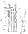
- FIGS. 4 and 5 show the interaction of in Fig. 1 shown nut (1, 41, 51) with the in Fig. 2 shown hose nozzle (7, 47, 57) and the in Fig. 3 shown hose connector (13, 413, 513).
- the upper figure shows the parts in their entirety, while the lower figure shows an enlarged detail showing the interaction of the clamping elements (5, 45, 55) with the structural element (16, 416, 516).
- Fig. 4 shows the clamping elements (45) in the open position
- Fig. 5 shows the clamping elements (55) in the closed position.
- the holding element 511 a has metallic contact with the structural element 516.
- Fig. 4 As can be seen, the nut (41) arranged on the hose stub (47) almost completely joins the hose connection part (413), for example by means of manual assembly are connected while the clamping elements (45) remain in the open position. This allows an alignment of the tube (419). Then, as in Fig. 5 shown, the structural element (516) at a certain point towards the end of the connection process, namely, when the nut (51) with the hose connector (513) is almost completely connected, for example by means of key assembly, the clamping elements (55) in the clamping position and transfer hold in the clamping position for the duration of the connection by means of a radial clamping force.
- FIG. 6 shows the interaction of a conventional hose connection 619 without positioning option and anti-rotation with a hose connection part 613 according to the invention, comprising structural element 616, which is designed so that the connection device also allows a connection with a counterpart, which has no inventive anti-rotation.
- This allows a gradual retrofitting of existing hose connections by the hose connection is first retrofitted with a hose connector according to the invention before retrofitting with a nut according to the invention and a hose nozzle according to the invention.
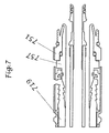
- FIG. 7 shows an embodiment comprising a hose nozzle (757) according to the invention and arranged on the hose nozzle nut (751).
Landscapes
- Engineering & Computer Science (AREA)
- General Engineering & Computer Science (AREA)
- Mechanical Engineering (AREA)
- Joints That Cut Off Fluids, And Hose Joints (AREA)
- Loading And Unloading Of Fuel Tanks Or Ships (AREA)
- Joints With Pressure Members (AREA)
- Quick-Acting Or Multi-Walled Pipe Joints (AREA)
Claims (13)
- Combinaison comprenant :a) une pièce de raccordement de flexible (13) pour un flexible hydraulique ;b) un embout de flexible (7) pour un autre flexible hydraulique ; etc) un écrou (1) destiné à être disposé sur l'embout de flexible (7) ;dans laquellei) l'écrou comporte un dispositif d'assemblage (2) qui peut être relié à la pièce de raccordement de flexible (13) de manière étanche aux liquides ; l'écrou comporte un réceptacle (3) pour l'embout de flexible (7), le réceptacle (3) comportant une première extrémité (3a) et une seconde extrémité (3b), le réceptacle (3) étant configuré pour entourer l'embout de flexible (7) selon une liaison par coopération de formes dans le sens de la circonférence de telle sorte que l'écrou (1) et l'embout de flexible (7) peuvent tourner l'un par rapport à l'autre dans le sens de la circonférence ; l'écrou comporte en outre une protection antitorsion (4) configurée de telle sorte qu'elle peut être déplacée par un élément structurel (16) de la pièce de raccordement de flexible (13) d'une position ouverte, dans laquelle l'écrou (1) et l'embout de flexible (7) peuvent tourner l'un par rapport à l'autre dans le sens de la circonférence lorsque l'écrou (1) est disposé sur l'embout de flexible (7), dans une position fermée dans laquelle une rotation de l'écrou (1) dans le sens de la circonférence par rapport à l'embout de flexible (7) est empêchée lorsque l'écrou (1) est disposé sur l'embout de flexible (7) ;ii) l'embout de flexible (7) comporte un manchon tubulaire (9) servant à fixer l'autre flexible hydraulique, la face extérieure de l'embout de flexible comportant une surface d'appui (10) pour l'écrou (1), les dimensions de l'embout de flexible (7) étant adaptées à celles de l'écrou (1) de façon que l'embout de flexible (7) peut être entouré par l'écrou (1) par coopération de formes dans le sens de la circonférence de telle sorte que l'embout de flexible (7) et l'écrou (1) peuvent tourner l'un par rapport à l'autre dans le sens de la circonférence ;iii) et la pièce de raccordement de flexible (13) comprend un conduit hydraulique (14) à une extrémité (14a) duquel est disposé un dispositif d'assemblage (15) qui permet un assemblage étanche aux liquides avec l'écrou (1), le dispositif d'assemblage (15) comprenant de préférence un filetage intérieur qui peut être relié à un filetage extérieur correspondant de l'écrou (1), la pièce de raccordement de flexible (13) comportant l'élément structurel (16) configuré pour déplacer la protection antitorsion (4) de l'écrou (1) de la position ouverte dans la position fermée.
- Combinaison selon la revendication 1, caractérisée en ce que l'écrou (1) est configuré de telle sorte que, à un certain point du processus d'assemblage entre l'écrou (1) et la pièce de raccordement de flexible (13), la protection antitorsion (4) est déplacée par l'élément structurel (16) de la pièce de raccordement de flexible (13) de la position ouverte dans la position fermée lorsque l'écrou (1) est relié à la pièce de raccordement de flexible (13) ; le point se situe de préférence vers la fin du processus d'assemblage, l'écrou (1) étant de préférence configuré de telle sorte que la protection antitorsion (4) coopère seulement à ce moment-là avec l'élément structurel (16) de la pièce de raccordement de flexible (13) pour déplacer la protection antitorsion (4) de la position ouverte dans la position fermée lorsque l'écrou (1) est presque entièrement relié à la pièce de raccordement de flexible (13).
- Combinaison selon l'une des revendications 1 ou 2, caractérisée en ce que la protection antitorsion (4) de l'écrou (1) comprend au moins un élément de serrage (5), de préférence disposé sur la face interne de l'écrou (1), qui peut être déplacé de la position ouverte, laquelle permet un mouvement de rotation de l'écrou (1) dans le sens de la circonférence par rapport à l'embout de flexible (7) lorsque l'écrou (1) est disposé sur l'embout de flexible (7), dans une position de serrage, dans laquelle ledit au moins un élément de serrage (5) est comprimé contre l'embout de flexible (7) afin d'empêcher un mouvement de rotation de l'écrou (1 par rapport à l'embout de flexible (7) dans le sens de la circonférence, lorsque l'écrou (1) est disposé sur l'embout de flexible (7), ledit au moins un élément de serrage (5) étant de préférence prévu pour être maintenu dans la position de serrage au moyen d'une force de serrage, de préférence une force de serrage radiale.
- Combinaison selon la revendication 3, dans laquellea) la protection antitorsion (4) de l'écrou (1) comprend au moins deux éléments de serrage (5), de préférence 2 à 12 éléments de serrage (5) de préférence espacés les uns des autres dans le sens de la circonférence, de préférence 4 à 8 éléments de serrage (5) de préférence espacés les uns des autres dans le sens de la circonférence, de manière particulièrement préférée 6 éléments de serrage (5) de préférence espacés les uns des autres dans le sens de la circonférence, et/oub) le dispositif d'assemblage (2) de l'écrou (1) comprend un filetage extérieur qui peut être relié de manière étanche aux liquides à un filetage intérieur correspondant de la pièce de raccordement de flexible (13), le ou les éléments de serrage (5) dépassant de préférence du filetage extérieur dans la direction axiale, et/ouc) le dispositif d'assemblage (2) de l'écrou (1) est disposé sur la face extérieure de l'écrou (1) dans la zone de la première extrémité (3a) du réceptacle (3) et/ou le ou les éléments de serrage (5) sont disposés sur la face interne de l'écrou (1) dans la zone de la première extrémité (3a) du réceptacle (3), et/oud) le réceptacle (3) pour l'embout de flexible (7) s'étend sur toute l'étendue axiale de l'écrou (1).
- Combinaison selon l'une des revendications 1 à 4, caractérisée en ce que l'écrou (1) est fait d'une matière synthétique, de préférence d'une matière synthétique électroconductrice, de manière particulièrement préférée d'une matière synthétique électroconductrice ayant une résistance électrique de 200 à 1000 ohms suivant la norme EN 13617-2, la matière synthétique étant de préférence choisie dans le groupe constitué par des polyamides (PA) et des polyétheréthercétones (PEEK).
- Combinaison selon l'une des revendications 1 à 5, dans laquelle l'écrou (1) est configuré de telle sorte que l'assemblage entre l'écrou (1) et la pièce de raccordement de flexible (13) résiste à des forces de traction (mesurées suivant la norme EN 13483 Annexe K) d'au moins 2000 N pendant 2 minutes, de préférence d'au moins 2000 N pendant 5 minutes.
- Combinaison selon l'une des revendications 1 à 6, caractérisée en ce que l'écrou (1) comporte des éléments de renforcement (6), les éléments de renforcement (6) étant de préférence espacés les uns des autres dans le sens de la circonférence et/ou de préférence disposés sur la face interne de l'écrou (1), de préférence dans la zone de la première extrémité (3a) du réceptacle (3), et/ou de préférence disposés dans la zone du dispositif d'assemblage (2).
- Combinaison selon l'une des revendications 1 à 7, caractérisée en ce que l'embout de flexible (7) comporte un dispositif de retenue (11) configuré pour empêcher un mouvement axial de l'écrou (1) par rapport à l'embout de flexible (7), le dispositif de retenue (11) comprenant de préférence deux éléments de retenue (11a, 11b) qui définissent entre eux la surface d'appui (10) pour l'écrou (1), de préférence au moins un des éléments de retenue (11a, 11b), de manière particulièrement préférée les deux éléments de retenue (11a, 11b) étant réalisé(s) en forme de collerette(s), la ou les collerettes s'étendant de préférence sans interruption dans le sens de la circonférence, l'embout de flexible (7) étant de préférence également configuré pour venir en contact par sa face extérieure avec une pièce de raccordement de flexible (13) afin de créer une continuité électrique, l'embout de flexible (7) étant de manière particulièrement préférée configuré pour venir en contact par un de ses éléments de retenue (11a) avec une pièce de raccordement de flexible (13) afin de créer une continuité électrique.
- Combinaison selon la revendication 3, caractérisée en ce que l'embout de flexible (7) comporte sur sa face extérieure au moins un segment (12) prévu pour servir de contre-appui, du moins en partie, audit au moins un élément de serrage (5) de l'écrou (1), ledit au moins un segment (12) prévu pour servir de contre-appui, du moins en partie, audit au moins un élément de serrage (5) de l'écrou (1) étant disposé de préférence dans la zone de la surface d'appui (10).
- Combinaison selon l'une des revendications 1 à 9, caractérisée en ce que l'élément structurel (16) de la pièce de raccordement de flexible (13) est disposé et dimensionné de telle sorte que, à un certain point du processus d'assemblage entre la pièce de raccordement de flexible (13) et l'écrou (1), la protection antitorsion (4) de l'écrou (1) est déplacée par l'élément structurel (16) de la pièce de raccordement de flexible (13) de la position ouverte dans la position fermée lorsque la pièce de raccordement de flexible (13) est reliée à l'écrou (1) ; dans laquelle le point se situe de préférence vers la fin du processus d'assemblage, la pièce de raccordement de flexible (13) étant de préférence configurée de telle façon que l'élément structurel (16) coopère seulement à ce moment-là avec l'écrou (1) pour déplacer la protection antitorsion (4) de la position ouverte dans la position fermée lorsque la pièce de raccordement de flexible (13) est presque entièrement reliée à l'écrou (1).
- Combinaison selon l'une des revendications 1 à 10, caractérisée en ce quea) l'élément structurel (16) de la pièce de raccordement de flexible (13) possède au moins une caractéristique, de préférence les deux caractéristiques, choisies dans le groupe des caractéristiques suivantes :- l'élément structurel (16) est de forme annulaire, de préférence circulaire,- l'élément structurel (16) est disposé dans la zone du dispositif d'assemblage (15) de la pièce de raccordement de flexible (13) dans laquelle l'élément structurel (16) est de préférence adjacent à la fin du filetage intérieur ;et/oub) l'élément structurel (16) de la pièce de raccordement de flexible (13) est configuré pour coopérer avec l'écrou (1), l'élément structurel possédant au moins une caractéristique, de préférence au moins deux caractéristiques, de manière particulièrement préférée l'ensemble des trois caractéristiques choisies dans le groupe des caractéristiques suivantes :- l'élément structurel (16) est configuré pour agir sur au moins un élément de serrage (5) de l'écrou (1),- l'élément structurel (16) est configuré pour exercer une force de serrage, de préférence une force de serrage radiale, sur ledit au moins un élément de serrage (5),- l'élément structurel (16) entraîne un rétrécissement du diamètre intérieur de la pièce de raccordement de flexible (13) de telle sorte qu'une force de serrage, de préférence une force de serrage radiale, est exercée sur ledit au moins un élément de serrage (5) de l'écrou (1) lorsque la pièce de raccordement de flexible (13) est reliée à l'écrou (1), l'élément structurel (16) étant de préférence configuré pour établir un contact métallique direct avec l'embout de flexible (7).
- Combinaison selon l'une des revendications 1 à 11, caractérisée en ce que la pièce de raccordement de flexible est une pièce de raccordement destinée à un flexible pour carburant et/ou pour gaz, plus préférentiellement un raccord de distributeur de carburant, de manière particulièrement préférée un raccord de distributeur de carburant pour flexible coaxial.
- Combinaison selon l'une des revendications 1 à 12, caractérisée en ce que l'écrou (1) est disposé sur l'embout de flexible (7).
Priority Applications (11)
| Application Number | Priority Date | Filing Date | Title |
|---|---|---|---|
| PL13187120T PL2857733T3 (pl) | 2013-10-02 | 2013-10-02 | Kombinacja, zawierająca część przyłączeniową węża, króciec węża i nakrętkę |
| DK13187120.4T DK2857733T3 (en) | 2013-10-02 | 2013-10-02 | Combination comprising a hose connector, hose connector and nut |
| ES13187120.4T ES2607123T3 (es) | 2013-10-02 | 2013-10-02 | Combinación que comprende una pieza de conexión de manguera, un racor de manguera y una tuerca |
| EP13187120.4A EP2857733B1 (fr) | 2013-10-02 | 2013-10-02 | Combinaison comportant une pièce de raccordement, un embout de tuyau souple et un écrou |
| PT131871204T PT2857733T (pt) | 2013-10-02 | 2013-10-02 | Combinação que compreende uma parte de ligação de mangueira, um bocal de mangueira e uma porca |
| CN201410493997.9A CN104514935B (zh) | 2013-10-02 | 2014-09-24 | 用于流体软管的螺母、软管接头和软管连接部件 |
| NZ700527A NZ700527A (en) | 2013-10-02 | 2014-09-30 | Nut, socket and adapter for a fluid nozzle |
| CA2866805A CA2866805C (fr) | 2013-10-02 | 2014-09-30 | Ecrou, douille et adaptateur pour buse de fluide |
| AU2014240198A AU2014240198B2 (en) | 2013-10-02 | 2014-09-30 | Nut, socket and adapter for a fluid nozzle |
| US14/504,897 US9494267B2 (en) | 2013-10-02 | 2014-10-02 | Nut, socket and adapter for a fluid nozzle |
| HK15109798.8A HK1209170B (en) | 2013-10-02 | 2015-10-07 | Nut, socket and adapter for a fluid nozzle |
Applications Claiming Priority (1)
| Application Number | Priority Date | Filing Date | Title |
|---|---|---|---|
| EP13187120.4A EP2857733B1 (fr) | 2013-10-02 | 2013-10-02 | Combinaison comportant une pièce de raccordement, un embout de tuyau souple et un écrou |
Publications (2)
| Publication Number | Publication Date |
|---|---|
| EP2857733A1 EP2857733A1 (fr) | 2015-04-08 |
| EP2857733B1 true EP2857733B1 (fr) | 2016-09-14 |
Family
ID=49304747
Family Applications (1)
| Application Number | Title | Priority Date | Filing Date |
|---|---|---|---|
| EP13187120.4A Active EP2857733B1 (fr) | 2013-10-02 | 2013-10-02 | Combinaison comportant une pièce de raccordement, un embout de tuyau souple et un écrou |
Country Status (10)
| Country | Link |
|---|---|
| US (1) | US9494267B2 (fr) |
| EP (1) | EP2857733B1 (fr) |
| CN (1) | CN104514935B (fr) |
| AU (1) | AU2014240198B2 (fr) |
| CA (1) | CA2866805C (fr) |
| DK (1) | DK2857733T3 (fr) |
| ES (1) | ES2607123T3 (fr) |
| NZ (1) | NZ700527A (fr) |
| PL (1) | PL2857733T3 (fr) |
| PT (1) | PT2857733T (fr) |
Cited By (1)
| Publication number | Priority date | Publication date | Assignee | Title |
|---|---|---|---|---|
| DE102023203559A1 (de) | 2023-04-19 | 2024-10-24 | Robert Bosch Gesellschaft mit beschränkter Haftung | Elektrochemische Zelleneinheit |
Families Citing this family (7)
| Publication number | Priority date | Publication date | Assignee | Title |
|---|---|---|---|---|
| EP2857733B1 (fr) | 2013-10-02 | 2016-09-14 | Elaflex Hiby Tanktechnik GmbH & Co. | Combinaison comportant une pièce de raccordement, un embout de tuyau souple et un écrou |
| WO2015068120A1 (fr) * | 2013-11-05 | 2015-05-14 | Plascon Group | Revêtement pour une cuve |
| US10561272B2 (en) * | 2013-11-05 | 2020-02-18 | Plascon Packaging, Inc. | Selectively sealable liner for a vessel |
| CN106247051B (zh) * | 2016-08-22 | 2018-04-24 | 开平市沃特卫浴有限公司 | 一种软管快接装置 |
| USD921855S1 (en) * | 2019-10-23 | 2021-06-08 | J.Juan S.A.U. | Connector for fluids |
| CN111365546A (zh) * | 2020-04-20 | 2020-07-03 | 嘉兴新亚科技股份有限公司 | 一种风电用不锈钢液压连接帽 |
| CN113803548A (zh) * | 2021-10-22 | 2021-12-17 | 安徽江淮汽车集团股份有限公司 | 软管连接接头 |
Family Cites Families (13)
| Publication number | Priority date | Publication date | Assignee | Title |
|---|---|---|---|---|
| US3895832A (en) * | 1974-05-13 | 1975-07-22 | Mueller Co | Collet compression connection |
| FR2435654A1 (fr) * | 1978-09-05 | 1980-04-04 | Martelli Louis | Raccords pour tuyaux souples ou tubes en un materiau ductile |
| US4951720A (en) * | 1987-09-18 | 1990-08-28 | Dayco Products, Inc. | Hose assembly and method of making the same |
| JPH0439492A (ja) * | 1990-05-31 | 1992-02-10 | Tokai Rubber Ind Ltd | クイックコネクタ |
| US5285744A (en) * | 1992-09-04 | 1994-02-15 | Vapor Systems Technologies, Inc. | Coaxial hose assembly |
| TW309581B (fr) * | 1994-09-15 | 1997-07-01 | Environ Prod Inc | |
| US5799834A (en) * | 1996-10-21 | 1998-09-01 | Marley Pump | Telescoping column pipe assembly for fuel dispensing pumping systems |
| US6412832B1 (en) * | 2000-06-08 | 2002-07-02 | Entegris, Inc. | Self-flaring plastic fittings |
| GB0504899D0 (en) * | 2005-03-09 | 2005-04-13 | Guest John Int Ltd | Improvements in or relating to tube couplings |
| US8371341B2 (en) * | 2009-09-24 | 2013-02-12 | Deleware Capital Formation, Inc. | Magnetically actuated vapor recovery valve |
| US20120001425A1 (en) * | 2010-07-02 | 2012-01-05 | Frank Ching King Lee | Fluid Line Connecting Fitting |
| EP2620684A1 (fr) * | 2012-01-24 | 2013-07-31 | Horacio Francisco Testa | Dispositif de couplage de tubes et accessoires tels que des bouchons, extensions et ergots |
| EP2857733B1 (fr) | 2013-10-02 | 2016-09-14 | Elaflex Hiby Tanktechnik GmbH & Co. | Combinaison comportant une pièce de raccordement, un embout de tuyau souple et un écrou |
-
2013
- 2013-10-02 EP EP13187120.4A patent/EP2857733B1/fr active Active
- 2013-10-02 DK DK13187120.4T patent/DK2857733T3/en active
- 2013-10-02 PL PL13187120T patent/PL2857733T3/pl unknown
- 2013-10-02 ES ES13187120.4T patent/ES2607123T3/es active Active
- 2013-10-02 PT PT131871204T patent/PT2857733T/pt unknown
-
2014
- 2014-09-24 CN CN201410493997.9A patent/CN104514935B/zh active Active
- 2014-09-30 AU AU2014240198A patent/AU2014240198B2/en active Active
- 2014-09-30 CA CA2866805A patent/CA2866805C/fr active Active
- 2014-09-30 NZ NZ700527A patent/NZ700527A/en unknown
- 2014-10-02 US US14/504,897 patent/US9494267B2/en active Active
Cited By (1)
| Publication number | Priority date | Publication date | Assignee | Title |
|---|---|---|---|---|
| DE102023203559A1 (de) | 2023-04-19 | 2024-10-24 | Robert Bosch Gesellschaft mit beschränkter Haftung | Elektrochemische Zelleneinheit |
Also Published As
| Publication number | Publication date |
|---|---|
| CA2866805C (fr) | 2021-03-30 |
| CN104514935B (zh) | 2017-06-06 |
| CN104514935A (zh) | 2015-04-15 |
| PT2857733T (pt) | 2016-12-29 |
| DK2857733T3 (en) | 2017-01-09 |
| AU2014240198B2 (en) | 2019-02-14 |
| HK1209170A1 (en) | 2016-03-24 |
| AU2014240198A1 (en) | 2015-04-16 |
| US20150091295A1 (en) | 2015-04-02 |
| PL2857733T3 (pl) | 2017-07-31 |
| CA2866805A1 (fr) | 2015-04-02 |
| EP2857733A1 (fr) | 2015-04-08 |
| NZ700527A (en) | 2016-08-26 |
| ES2607123T3 (es) | 2017-03-29 |
| US9494267B2 (en) | 2016-11-15 |
Similar Documents
| Publication | Publication Date | Title |
|---|---|---|
| EP2857733B1 (fr) | Combinaison comportant une pièce de raccordement, un embout de tuyau souple et un écrou | |
| EP2025280B1 (fr) | Dispositif de prise sur un flexible d'aspirateur | |
| EP2957681A2 (fr) | Robinetterie sanitaire a systeme de tuyau interne | |
| EP2685012A1 (fr) | Robinet comprenant un bec rotateur | |
| DE4029792A1 (de) | Anordnung zur befestigung einer handbrause | |
| WO2015062678A1 (fr) | Tuyau flexible et son procédé de fabrication | |
| EP2453157B1 (fr) | Système de raccord pour l'installation d'un appareil de conduite de l'eau | |
| WO2013030102A1 (fr) | Appareil de montage préalable de bague coupante pour raccords filetés pour tube | |
| EP1496164B1 (fr) | Raccordement du raccord d'un conduit par correspondance de forme | |
| DE102010051581A1 (de) | Steckdose für eine Steckverbindung | |
| EP1484544B1 (fr) | Traversée de conduite pour l'installation d'un tube sanitaire à travers un mur | |
| EP2460943B1 (fr) | Réservoir de chasse d'eau | |
| DE19936413C1 (de) | Schlauchanschluß | |
| EP3012502B1 (fr) | Dispositif de raccordement pour un tuyau et tuyau avec un tel dispositif | |
| DE102014012335A1 (de) | Elektrisches Gerät | |
| DE9017255U1 (de) | Wasserkasten mit einer Ablaßschraube | |
| EP0804970A2 (fr) | Pistolet de pulvérisation à main pour appareil de nettoyage haute pression | |
| DE4039663C2 (fr) | ||
| EP0933260A2 (fr) | Citerne pour recevoir des liquides | |
| DE20303522U1 (de) | Absperrventil | |
| EP4001724B1 (fr) | Dispositif de raccordement pour composants guidant des milieux | |
| EP2194308B1 (fr) | Pièce de couplage pour pièces de raccordement de tuyau annelé | |
| DE102013020652A1 (de) | Sanitärarmatur mit Anschlussadapter | |
| DE10326300A1 (de) | Sanitärschlauch mit drehbarer Kupplung für ein Anschlussstück | |
| AT527312B1 (de) | Vorrichtung zur Verbindung einer Sanitärarmatur mit einer Fluidleitung |
Legal Events
| Date | Code | Title | Description |
|---|---|---|---|
| PUAI | Public reference made under article 153(3) epc to a published international application that has entered the european phase |
Free format text: ORIGINAL CODE: 0009012 |
|
| 17P | Request for examination filed |
Effective date: 20131002 |
|
| AK | Designated contracting states |
Kind code of ref document: A1 Designated state(s): AL AT BE BG CH CY CZ DE DK EE ES FI FR GB GR HR HU IE IS IT LI LT LU LV MC MK MT NL NO PL PT RO RS SE SI SK SM TR |
|
| AX | Request for extension of the european patent |
Extension state: BA ME |
|
| R17P | Request for examination filed (corrected) |
Effective date: 20151008 |
|
| RBV | Designated contracting states (corrected) |
Designated state(s): AL AT BE BG CH CY CZ DE DK EE ES FI FR GB GR HR HU IE IS IT LI LT LU LV MC MK MT NL NO PL PT RO RS SE SI SK SM TR |
|
| RIC1 | Information provided on ipc code assigned before grant |
Ipc: F16B 39/32 20060101ALN20160229BHEP Ipc: F16L 33/22 20060101ALI20160229BHEP Ipc: F16L 19/00 20060101ALI20160229BHEP Ipc: F16L 39/02 20060101ALI20160229BHEP Ipc: F16L 25/01 20060101ALI20160229BHEP Ipc: B67D 7/32 20100101ALI20160229BHEP Ipc: B67D 7/04 20100101ALN20160229BHEP Ipc: F16L 19/065 20060101AFI20160229BHEP |
|
| GRAP | Despatch of communication of intention to grant a patent |
Free format text: ORIGINAL CODE: EPIDOSNIGR1 |
|
| RIC1 | Information provided on ipc code assigned before grant |
Ipc: B67D 7/04 20100101ALN20160307BHEP Ipc: B67D 7/32 20100101ALI20160307BHEP Ipc: F16L 39/02 20060101ALI20160307BHEP Ipc: F16B 39/32 20060101ALN20160307BHEP Ipc: F16L 33/22 20060101ALI20160307BHEP Ipc: F16L 19/065 20060101AFI20160307BHEP Ipc: F16L 19/00 20060101ALI20160307BHEP Ipc: F16L 25/01 20060101ALI20160307BHEP |
|
| INTG | Intention to grant announced |
Effective date: 20160408 |
|
| GRAS | Grant fee paid |
Free format text: ORIGINAL CODE: EPIDOSNIGR3 |
|
| GRAA | (expected) grant |
Free format text: ORIGINAL CODE: 0009210 |
|
| AK | Designated contracting states |
Kind code of ref document: B1 Designated state(s): AL AT BE BG CH CY CZ DE DK EE ES FI FR GB GR HR HU IE IS IT LI LT LU LV MC MK MT NL NO PL PT RO RS SE SI SK SM TR |
|
| REG | Reference to a national code |
Ref country code: GB Ref legal event code: FG4D Free format text: NOT ENGLISH |
|
| REG | Reference to a national code |
Ref country code: CH Ref legal event code: EP |
|
| REG | Reference to a national code |
Ref country code: IE Ref legal event code: FG4D Free format text: LANGUAGE OF EP DOCUMENT: GERMAN |
|
| REG | Reference to a national code |
Ref country code: AT Ref legal event code: REF Ref document number: 829392 Country of ref document: AT Kind code of ref document: T Effective date: 20161015 |
|
| REG | Reference to a national code |
Ref country code: DE Ref legal event code: R096 Ref document number: 502013004479 Country of ref document: DE |
|
| REG | Reference to a national code |
Ref country code: FR Ref legal event code: PLFP Year of fee payment: 4 |
|
| REG | Reference to a national code |
Ref country code: NL Ref legal event code: FP |
|
| REG | Reference to a national code |
Ref country code: PT Ref legal event code: SC4A Ref document number: 2857733 Country of ref document: PT Date of ref document: 20161229 Kind code of ref document: T Free format text: AVAILABILITY OF NATIONAL TRANSLATION Effective date: 20161212 |
|
| REG | Reference to a national code |
Ref country code: SE Ref legal event code: TRGR |
|
| REG | Reference to a national code |
Ref country code: DK Ref legal event code: T3 Effective date: 20170104 |
|
| REG | Reference to a national code |
Ref country code: LT Ref legal event code: MG4D |
|
| PG25 | Lapsed in a contracting state [announced via postgrant information from national office to epo] |
Ref country code: FI Free format text: LAPSE BECAUSE OF FAILURE TO SUBMIT A TRANSLATION OF THE DESCRIPTION OR TO PAY THE FEE WITHIN THE PRESCRIBED TIME-LIMIT Effective date: 20160914 Ref country code: RS Free format text: LAPSE BECAUSE OF FAILURE TO SUBMIT A TRANSLATION OF THE DESCRIPTION OR TO PAY THE FEE WITHIN THE PRESCRIBED TIME-LIMIT Effective date: 20160914 Ref country code: HR Free format text: LAPSE BECAUSE OF FAILURE TO SUBMIT A TRANSLATION OF THE DESCRIPTION OR TO PAY THE FEE WITHIN THE PRESCRIBED TIME-LIMIT Effective date: 20160914 Ref country code: NO Free format text: LAPSE BECAUSE OF FAILURE TO SUBMIT A TRANSLATION OF THE DESCRIPTION OR TO PAY THE FEE WITHIN THE PRESCRIBED TIME-LIMIT Effective date: 20161214 Ref country code: LT Free format text: LAPSE BECAUSE OF FAILURE TO SUBMIT A TRANSLATION OF THE DESCRIPTION OR TO PAY THE FEE WITHIN THE PRESCRIBED TIME-LIMIT Effective date: 20160914 |
|
| PG25 | Lapsed in a contracting state [announced via postgrant information from national office to epo] |
Ref country code: LV Free format text: LAPSE BECAUSE OF FAILURE TO SUBMIT A TRANSLATION OF THE DESCRIPTION OR TO PAY THE FEE WITHIN THE PRESCRIBED TIME-LIMIT Effective date: 20160914 Ref country code: BE Free format text: LAPSE BECAUSE OF NON-PAYMENT OF DUE FEES Effective date: 20161031 |
|
| PG25 | Lapsed in a contracting state [announced via postgrant information from national office to epo] |
Ref country code: RO Free format text: LAPSE BECAUSE OF FAILURE TO SUBMIT A TRANSLATION OF THE DESCRIPTION OR TO PAY THE FEE WITHIN THE PRESCRIBED TIME-LIMIT Effective date: 20160914 Ref country code: EE Free format text: LAPSE BECAUSE OF FAILURE TO SUBMIT A TRANSLATION OF THE DESCRIPTION OR TO PAY THE FEE WITHIN THE PRESCRIBED TIME-LIMIT Effective date: 20160914 |
|
| PG25 | Lapsed in a contracting state [announced via postgrant information from national office to epo] |
Ref country code: SM Free format text: LAPSE BECAUSE OF FAILURE TO SUBMIT A TRANSLATION OF THE DESCRIPTION OR TO PAY THE FEE WITHIN THE PRESCRIBED TIME-LIMIT Effective date: 20160914 Ref country code: IS Free format text: LAPSE BECAUSE OF FAILURE TO SUBMIT A TRANSLATION OF THE DESCRIPTION OR TO PAY THE FEE WITHIN THE PRESCRIBED TIME-LIMIT Effective date: 20170114 Ref country code: CZ Free format text: LAPSE BECAUSE OF FAILURE TO SUBMIT A TRANSLATION OF THE DESCRIPTION OR TO PAY THE FEE WITHIN THE PRESCRIBED TIME-LIMIT Effective date: 20160914 Ref country code: BG Free format text: LAPSE BECAUSE OF FAILURE TO SUBMIT A TRANSLATION OF THE DESCRIPTION OR TO PAY THE FEE WITHIN THE PRESCRIBED TIME-LIMIT Effective date: 20161214 Ref country code: SK Free format text: LAPSE BECAUSE OF FAILURE TO SUBMIT A TRANSLATION OF THE DESCRIPTION OR TO PAY THE FEE WITHIN THE PRESCRIBED TIME-LIMIT Effective date: 20160914 |
|
| REG | Reference to a national code |
Ref country code: CH Ref legal event code: PL |
|
| REG | Reference to a national code |
Ref country code: DE Ref legal event code: R097 Ref document number: 502013004479 Country of ref document: DE |
|
| REG | Reference to a national code |
Ref country code: GR Ref legal event code: EP Ref document number: 20160403101 Country of ref document: GR Effective date: 20170410 |
|
| PLBE | No opposition filed within time limit |
Free format text: ORIGINAL CODE: 0009261 |
|
| STAA | Information on the status of an ep patent application or granted ep patent |
Free format text: STATUS: NO OPPOSITION FILED WITHIN TIME LIMIT |
|
| REG | Reference to a national code |
Ref country code: IE Ref legal event code: MM4A |
|
| PG25 | Lapsed in a contracting state [announced via postgrant information from national office to epo] |
Ref country code: LI Free format text: LAPSE BECAUSE OF NON-PAYMENT OF DUE FEES Effective date: 20161031 Ref country code: CH Free format text: LAPSE BECAUSE OF NON-PAYMENT OF DUE FEES Effective date: 20161031 |
|
| 26N | No opposition filed |
Effective date: 20170615 |
|
| PG25 | Lapsed in a contracting state [announced via postgrant information from national office to epo] |
Ref country code: LU Free format text: LAPSE BECAUSE OF NON-PAYMENT OF DUE FEES Effective date: 20161002 |
|
| REG | Reference to a national code |
Ref country code: FR Ref legal event code: PLFP Year of fee payment: 5 |
|
| PG25 | Lapsed in a contracting state [announced via postgrant information from national office to epo] |
Ref country code: SI Free format text: LAPSE BECAUSE OF FAILURE TO SUBMIT A TRANSLATION OF THE DESCRIPTION OR TO PAY THE FEE WITHIN THE PRESCRIBED TIME-LIMIT Effective date: 20160914 Ref country code: IE Free format text: LAPSE BECAUSE OF NON-PAYMENT OF DUE FEES Effective date: 20161002 |
|
| REG | Reference to a national code |
Ref country code: BE Ref legal event code: MM Effective date: 20161031 |
|
| PG25 | Lapsed in a contracting state [announced via postgrant information from national office to epo] |
Ref country code: HU Free format text: LAPSE BECAUSE OF FAILURE TO SUBMIT A TRANSLATION OF THE DESCRIPTION OR TO PAY THE FEE WITHIN THE PRESCRIBED TIME-LIMIT; INVALID AB INITIO Effective date: 20131002 |
|
| PG25 | Lapsed in a contracting state [announced via postgrant information from national office to epo] |
Ref country code: MC Free format text: LAPSE BECAUSE OF FAILURE TO SUBMIT A TRANSLATION OF THE DESCRIPTION OR TO PAY THE FEE WITHIN THE PRESCRIBED TIME-LIMIT Effective date: 20160914 Ref country code: MK Free format text: LAPSE BECAUSE OF FAILURE TO SUBMIT A TRANSLATION OF THE DESCRIPTION OR TO PAY THE FEE WITHIN THE PRESCRIBED TIME-LIMIT Effective date: 20160914 Ref country code: CY Free format text: LAPSE BECAUSE OF FAILURE TO SUBMIT A TRANSLATION OF THE DESCRIPTION OR TO PAY THE FEE WITHIN THE PRESCRIBED TIME-LIMIT Effective date: 20160914 Ref country code: MT Free format text: LAPSE BECAUSE OF FAILURE TO SUBMIT A TRANSLATION OF THE DESCRIPTION OR TO PAY THE FEE WITHIN THE PRESCRIBED TIME-LIMIT Effective date: 20160914 |
|
| REG | Reference to a national code |
Ref country code: FR Ref legal event code: PLFP Year of fee payment: 6 |
|
| PG25 | Lapsed in a contracting state [announced via postgrant information from national office to epo] |
Ref country code: AL Free format text: LAPSE BECAUSE OF FAILURE TO SUBMIT A TRANSLATION OF THE DESCRIPTION OR TO PAY THE FEE WITHIN THE PRESCRIBED TIME-LIMIT Effective date: 20160914 |
|
| P01 | Opt-out of the competence of the unified patent court (upc) registered |
Effective date: 20230516 |
|
| PGFP | Annual fee paid to national office [announced via postgrant information from national office to epo] |
Ref country code: PT Payment date: 20250924 Year of fee payment: 13 |
|
| PGFP | Annual fee paid to national office [announced via postgrant information from national office to epo] |
Ref country code: TR Payment date: 20250925 Year of fee payment: 13 Ref country code: PL Payment date: 20250908 Year of fee payment: 13 |
|
| PGFP | Annual fee paid to national office [announced via postgrant information from national office to epo] |
Ref country code: NL Payment date: 20251023 Year of fee payment: 13 |
|
| PGFP | Annual fee paid to national office [announced via postgrant information from national office to epo] |
Ref country code: DE Payment date: 20251028 Year of fee payment: 13 |
|
| PGFP | Annual fee paid to national office [announced via postgrant information from national office to epo] |
Ref country code: GB Payment date: 20251024 Year of fee payment: 13 |
|
| PGFP | Annual fee paid to national office [announced via postgrant information from national office to epo] |
Ref country code: AT Payment date: 20251021 Year of fee payment: 13 |
|
| PGFP | Annual fee paid to national office [announced via postgrant information from national office to epo] |
Ref country code: DK Payment date: 20251023 Year of fee payment: 13 Ref country code: IT Payment date: 20251031 Year of fee payment: 13 |
|
| PGFP | Annual fee paid to national office [announced via postgrant information from national office to epo] |
Ref country code: FR Payment date: 20251022 Year of fee payment: 13 |
|
| PGFP | Annual fee paid to national office [announced via postgrant information from national office to epo] |
Ref country code: GR Payment date: 20251021 Year of fee payment: 13 |
|
| PGFP | Annual fee paid to national office [announced via postgrant information from national office to epo] |
Ref country code: SE Payment date: 20251023 Year of fee payment: 13 |
|
| PGFP | Annual fee paid to national office [announced via postgrant information from national office to epo] |
Ref country code: ES Payment date: 20251114 Year of fee payment: 13 |