EP0933436A1 - Vorrichtung und Verfahren zum Schmelzen von direkt-reduziertem Eisen - Google Patents
Vorrichtung und Verfahren zum Schmelzen von direkt-reduziertem Eisen Download PDFInfo
- Publication number
- EP0933436A1 EP0933436A1 EP98870023A EP98870023A EP0933436A1 EP 0933436 A1 EP0933436 A1 EP 0933436A1 EP 98870023 A EP98870023 A EP 98870023A EP 98870023 A EP98870023 A EP 98870023A EP 0933436 A1 EP0933436 A1 EP 0933436A1
- Authority
- EP
- European Patent Office
- Prior art keywords
- installation according
- unit
- installation
- slag
- iron
- Prior art date
- Legal status (The legal status is an assumption and is not a legal conclusion. Google has not performed a legal analysis and makes no representation as to the accuracy of the status listed.)
- Withdrawn
Links
- 238000009434 installation Methods 0.000 title claims abstract description 45
- XEEYBQQBJWHFJM-UHFFFAOYSA-N Iron Chemical compound [Fe] XEEYBQQBJWHFJM-UHFFFAOYSA-N 0.000 title claims abstract description 26
- 238000000034 method Methods 0.000 title claims abstract description 10
- 238000002844 melting Methods 0.000 title claims abstract description 9
- 230000008018 melting Effects 0.000 title claims abstract description 9
- 230000008569 process Effects 0.000 title claims description 9
- 239000007789 gas Substances 0.000 claims abstract description 22
- 239000002893 slag Substances 0.000 claims abstract description 18
- 239000000463 material Substances 0.000 claims abstract description 15
- 229910001018 Cast iron Inorganic materials 0.000 claims abstract description 13
- 229910052742 iron Inorganic materials 0.000 claims abstract description 13
- 239000007788 liquid Substances 0.000 claims abstract description 11
- 238000006477 desulfuration reaction Methods 0.000 claims abstract description 4
- 230000023556 desulfurization Effects 0.000 claims abstract description 4
- 238000004519 manufacturing process Methods 0.000 claims description 10
- 230000009467 reduction Effects 0.000 claims description 9
- 230000004927 fusion Effects 0.000 claims description 8
- 239000003245 coal Substances 0.000 claims description 6
- 238000011144 upstream manufacturing Methods 0.000 claims description 6
- 229910000805 Pig iron Inorganic materials 0.000 claims description 5
- OKTJSMMVPCPJKN-UHFFFAOYSA-N Carbon Chemical compound [C] OKTJSMMVPCPJKN-UHFFFAOYSA-N 0.000 claims description 4
- 229910052799 carbon Inorganic materials 0.000 claims description 4
- 238000002485 combustion reaction Methods 0.000 claims description 3
- 235000013365 dairy product Nutrition 0.000 claims description 3
- 238000006073 displacement reaction Methods 0.000 claims description 3
- 238000010405 reoxidation reaction Methods 0.000 claims description 3
- 230000000284 resting effect Effects 0.000 claims description 3
- 238000000926 separation method Methods 0.000 claims description 3
- 239000007787 solid Substances 0.000 claims description 3
- 230000005540 biological transmission Effects 0.000 claims description 2
- 239000000470 constituent Substances 0.000 claims description 2
- 239000011261 inert gas Substances 0.000 claims description 2
- 230000000750 progressive effect Effects 0.000 claims description 2
- 238000010992 reflux Methods 0.000 claims description 2
- 238000007789 sealing Methods 0.000 claims description 2
- 239000002699 waste material Substances 0.000 claims description 2
- 238000009749 continuous casting Methods 0.000 claims 1
- 238000000605 extraction Methods 0.000 claims 1
- 239000000155 melt Substances 0.000 claims 1
- 239000000779 smoke Substances 0.000 claims 1
- 238000002347 injection Methods 0.000 abstract description 4
- 239000007924 injection Substances 0.000 abstract description 4
- 238000007599 discharging Methods 0.000 abstract 1
- 238000005266 casting Methods 0.000 description 3
- 239000011248 coating agent Substances 0.000 description 3
- 238000000576 coating method Methods 0.000 description 3
- IJGRMHOSHXDMSA-UHFFFAOYSA-N Atomic nitrogen Chemical compound N#N IJGRMHOSHXDMSA-UHFFFAOYSA-N 0.000 description 2
- 239000000446 fuel Substances 0.000 description 2
- VNWKTOKETHGBQD-UHFFFAOYSA-N methane Chemical compound C VNWKTOKETHGBQD-UHFFFAOYSA-N 0.000 description 2
- 238000011084 recovery Methods 0.000 description 2
- 238000004064 recycling Methods 0.000 description 2
- 229910000831 Steel Inorganic materials 0.000 description 1
- QVGXLLKOCUKJST-UHFFFAOYSA-N atomic oxygen Chemical compound [O] QVGXLLKOCUKJST-UHFFFAOYSA-N 0.000 description 1
- 230000008859 change Effects 0.000 description 1
- 239000000571 coke Substances 0.000 description 1
- 239000000567 combustion gas Substances 0.000 description 1
- 230000001143 conditioned effect Effects 0.000 description 1
- 238000005553 drilling Methods 0.000 description 1
- 238000005265 energy consumption Methods 0.000 description 1
- 230000003628 erosive effect Effects 0.000 description 1
- 239000003546 flue gas Substances 0.000 description 1
- 230000006698 induction Effects 0.000 description 1
- -1 iron carbides Chemical class 0.000 description 1
- UQSXHKLRYXJYBZ-UHFFFAOYSA-N iron oxide Inorganic materials [Fe]=O UQSXHKLRYXJYBZ-UHFFFAOYSA-N 0.000 description 1
- 235000013980 iron oxide Nutrition 0.000 description 1
- VBMVTYDPPZVILR-UHFFFAOYSA-N iron(2+);oxygen(2-) Chemical class [O-2].[Fe+2] VBMVTYDPPZVILR-UHFFFAOYSA-N 0.000 description 1
- 239000003345 natural gas Substances 0.000 description 1
- 229910052757 nitrogen Inorganic materials 0.000 description 1
- 239000003921 oil Substances 0.000 description 1
- 239000001301 oxygen Substances 0.000 description 1
- 229910052760 oxygen Inorganic materials 0.000 description 1
- 230000035515 penetration Effects 0.000 description 1
- 239000004033 plastic Substances 0.000 description 1
- 229920003023 plastic Polymers 0.000 description 1
- 230000005855 radiation Effects 0.000 description 1
- 238000011946 reduction process Methods 0.000 description 1
- 239000011819 refractory material Substances 0.000 description 1
- 230000008439 repair process Effects 0.000 description 1
- 239000010959 steel Substances 0.000 description 1
- 238000009628 steelmaking Methods 0.000 description 1
- 239000000126 substance Substances 0.000 description 1
- 230000008685 targeting Effects 0.000 description 1
Images


Classifications
-
- F—MECHANICAL ENGINEERING; LIGHTING; HEATING; WEAPONS; BLASTING
- F27—FURNACES; KILNS; OVENS; RETORTS
- F27B—FURNACES, KILNS, OVENS OR RETORTS IN GENERAL; OPEN SINTERING OR LIKE APPARATUS
- F27B7/00—Rotary-drum furnaces, i.e. horizontal or slightly inclined
- F27B7/20—Details, accessories or equipment specially adapted for rotary-drum furnaces
- F27B7/2083—Arrangements for the melting of metals or the treatment of molten metals
-
- C—CHEMISTRY; METALLURGY
- C21—METALLURGY OF IRON
- C21B—MANUFACTURE OF IRON OR STEEL
- C21B11/00—Making pig-iron other than in blast furnaces
- C21B11/06—Making pig-iron other than in blast furnaces in rotary kilns
-
- C—CHEMISTRY; METALLURGY
- C21—METALLURGY OF IRON
- C21B—MANUFACTURE OF IRON OR STEEL
- C21B13/00—Making spongy iron or liquid steel, by direct processes
- C21B13/08—Making spongy iron or liquid steel, by direct processes in rotary furnaces
- C21B13/085—Making spongy iron or liquid steel, by direct processes in rotary furnaces wherein iron or steel is obtained in a molten state
-
- C—CHEMISTRY; METALLURGY
- C21—METALLURGY OF IRON
- C21B—MANUFACTURE OF IRON OR STEEL
- C21B13/00—Making spongy iron or liquid steel, by direct processes
- C21B13/14—Multi-stage processes processes carried out in different vessels or furnaces
-
- C—CHEMISTRY; METALLURGY
- C21—METALLURGY OF IRON
- C21C—PROCESSING OF PIG-IRON, e.g. REFINING, MANUFACTURE OF WROUGHT-IRON OR STEEL; TREATMENT IN MOLTEN STATE OF FERROUS ALLOYS
- C21C5/00—Manufacture of carbon-steel, e.g. plain mild steel, medium carbon steel or cast steel or stainless steel
- C21C5/56—Manufacture of steel by other methods
-
- F—MECHANICAL ENGINEERING; LIGHTING; HEATING; WEAPONS; BLASTING
- F27—FURNACES; KILNS; OVENS; RETORTS
- F27B—FURNACES, KILNS, OVENS OR RETORTS IN GENERAL; OPEN SINTERING OR LIKE APPARATUS
- F27B7/00—Rotary-drum furnaces, i.e. horizontal or slightly inclined
- F27B7/20—Details, accessories or equipment specially adapted for rotary-drum furnaces
- F27B7/34—Arrangements of heating devices
-
- F—MECHANICAL ENGINEERING; LIGHTING; HEATING; WEAPONS; BLASTING
- F27—FURNACES; KILNS; OVENS; RETORTS
- F27D—DETAILS OR ACCESSORIES OF FURNACES, KILNS, OVENS OR RETORTS, IN SO FAR AS THEY ARE OF KINDS OCCURRING IN MORE THAN ONE KIND OF FURNACE
- F27D17/00—Arrangements for using waste heat; Arrangements for using, or disposing of, waste gases
- F27D17/30—Arrangements for extraction or collection of waste gases; Hoods therefor
-
- F—MECHANICAL ENGINEERING; LIGHTING; HEATING; WEAPONS; BLASTING
- F27—FURNACES; KILNS; OVENS; RETORTS
- F27B—FURNACES, KILNS, OVENS OR RETORTS IN GENERAL; OPEN SINTERING OR LIKE APPARATUS
- F27B7/00—Rotary-drum furnaces, i.e. horizontal or slightly inclined
- F27B7/20—Details, accessories or equipment specially adapted for rotary-drum furnaces
- F27B7/32—Arrangement of devices for charging
- F27B7/3205—Charging
- F27B2007/3211—Charging at the open end of the drum
-
- F—MECHANICAL ENGINEERING; LIGHTING; HEATING; WEAPONS; BLASTING
- F27—FURNACES; KILNS; OVENS; RETORTS
- F27B—FURNACES, KILNS, OVENS OR RETORTS IN GENERAL; OPEN SINTERING OR LIKE APPARATUS
- F27B7/00—Rotary-drum furnaces, i.e. horizontal or slightly inclined
- F27B7/20—Details, accessories or equipment specially adapted for rotary-drum furnaces
- F27B7/22—Rotary drums; Supports therefor
- F27B7/24—Seals between rotary and stationary parts
Definitions
- the present invention relates to a liquid iron production facility, allowing carry out the final DRI merger and reduction, which are iron sponges or iron carbides produced at the outset of iron oxides by a direct reduction process, in a rotary melting furnace with horizontal axis of rotation.
- DRIs are obtained in particular for example by gas reduction (HYL, Midrex process) or by reduction from carbon sources as in SL-RN, Fastmet, Inmetco or Circofer, Comet or according to the patent application filed by the plaintiff on 01/28/1998.
- the DRI is directly, after its production, implemented in the melting furnace, for reduce latent heat loss.
- the invention relates also on a process using the installation described.
- the invention aims to produce cast iron liquid, preferably desulfurized, for processing steels from eg electric ovens or BOF type converters, in order to reduce the duration of the development cycle of these compared to the cycles to charging of DRI.
- the invention aims to achieve a design constructive that is simple, compact and inexpensive.
- the installation of the invention also aims to obtain an increased service life of the refractory lining that the typical phenomena of erosion and attack chemical appearing in the slag, for example in an electric oven, are avoided due to the continuous rotation of the melting furnace around its axis of horizontal rotation.
- the equipment in the casting area is particularly simple and safe, no capping machine and drilling for casting is only required as in the case of a blast furnace casting floor.
- the process produces a slag, characteristics close to that of blast furnaces, can be easily valued which is not the case for dairy produced by direct loading of DRI into a steel making process.
- the installation according to the invention is essentially constituted by the power supply unit of the material to be treated, preferably coming directly of a DRI production unit, at a temperature also as high as possible.
- This feed element leads to one end of a rotary tubular oven whose end opposite is open and connected on the one hand to a unit removal of pig iron and slag, preferably in funnel-shaped, and secondly to an evacuation unit gases.
- a burner located on the supply side ensures the heat input necessary for the melting of the material to be treated while an injection lance, located at the other end of the oven, performs the desulfurization of the bath.
- the burner can be placed on the drain side or even split if the behavior of the merger requires it.
- the constituent elements of the installation are mounted on a chassis common so that you can tilt the whole.
- conventional oven is preferably mounted on crowns resting on rollers driven by motors and adequate transmissions.
- the exhaust gas unit collects basically hot flue gases, and it's preferably connected directly to the installation of production of DRI which provides the material to be treated in the installation.
- the supply unit is consisting of a feed chute or any other adequate supply system such as an Archimedes screw, which is mounted on a disc into which also opens the universal burner.
- a powdered coal injector in order to on the one hand to avoid reoxidation of the charge, and on the other hand to carry out the final reduction of the iron sponge and to add to the bath the carbon necessary to obtain a quality cast iron.
- This disc is fixed and connects to a end of the rotary kiln, for example through double seals mounted on a compensator, the intermediate chamber of the seal which can preferably be pressurization of inert gas, preferably nitrogen, the assembly allowing the relative movement between the disc fixed and the rotary kiln and taking up the expansions thermal.
- the power unit is itself connected to a duct or a trough connected to the unit of DRI production.
- the pivot point of the chassis view of adjusting the inclination of the axis of rotation of the oven fusion, is ideally located at the center of the connection surface of the supply duct. This device makes it possible to adjust the flow rate of cast iron to be removed or even interrupt the payment, for example to change the liquid iron discharge device.
- a valve preferably a double valve, which allows the passage of solids but prevents gas reflux to the furnace for producing DRI, can be planned, preferably upstream of the point of aforementioned rotation.
- the evacuation unit for gas is connected by a compensator of the same type as above to a fixed external duct.
- the whole installation is of course provided with a coating of refractory material.
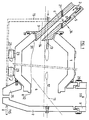
- FIG. 1 The installation shown in Figure 1 is essentially consisting on the one hand by a rotary kiln 1 provided at one end (upstream end taking into account the direction of material movement) by one unit supply 3 of DRI 2 and at the other end (side downstream) of an opening 4 connected to a discharge unit 7 of liquid iron and slag and one unit gas exhaust 9.
- FIG. 2 shows the power unit 3 composed inter alia of a disk 3, forming a buffer, provided with an inclined feed chute 6.
- a burner 13 opens into an oven.
- the length of penetration of the burner into the oven is adjustable in order to optimize the fusion of the heap of DRI 31 to the inlet of the oven 1.
- This burner can be mounted on the side opposite, it can also be split by having a burner on each side.
- Disc 3 can also be provided with an injector 14 of powdered coal.
- a joint sealing device 19 allows the rotation of the oven by compared to fixed disk.
- the other end of the oven is open and leads on the one hand to unit 35 and on the other hand to unit 9.
- Suitable seals 20 are again designed to allow the oven to rotate.
- the assembly constituted by the oven 1 and the units 3, 7 and 35 (or 37) is carried by a chassis 15. It is on this chassis that rollers are mounted 25 supporting the rotary kiln 1. This kiln is itself provided of crowns 23 resting on the rollers. The rollers 25 are driven directly or indirectly by a motor.
- Connecting the ends of the trunking 6 to the duct 5 is produced by a compressible element 21.
- the entire chassis, with the rotary 1 and stationary equipment 3, 7 and 35 (or 37) that supports, can be tilted from the horizontal on the pivot point 34 located at this connection.
- connection to the gas 7 to a recycling duct 9 to the DRI oven and its tightness is achieved by a compensator 29.
- a second work situation is that in which the oven must undergo a major overhaul. In this case, it suffices to separate the chute 6 from the conduit 5 to be able to move the chassis with the unit integrated.
- the installation can also be dismantled by separating the oven 1 from the unit 3 at one end and units 7 and 35 (or 37) at the other end (with disassembly, of course, of the various seals and compensators).
- the installation of the invention is designed so that it can be very quickly be dismantled and replaced by a complete reserve installation, partially dismantled and replaced by one of its components constitutive.
- Both oven 1 and units 3, 7, 9 and 35 (or 37) are provided with a refractory lining adequate capable of withstanding temperatures and charge.
- the liquid iron discharge unit which preferably affects the shape of a funnel 35 as represented in figure 1, can be provided with a siphon 37 as for example shown in FIG. 3, a dam 43 ensuring the separation of the slag 41 and the cast iron produced 39.
- the geometry of the disc 3 as well as that of the oven liner 1 where they join is chosen in a timely manner to ensure the best possible operation of the installation.
- the material to process in addition to its merger, undergoes a final reduction in the furnace and carburetion up to a content of 4% carbon through the injection of powdered coal.
- the heat necessary for the fusion is ensured essentially by radiation from the burner flame above of the load and by that of the walls of the furnace.
- the hot refractory lining of the rotary kiln heats the bath by direct contact.
- the burner mounted on disc 3 can advantageously be moved longitudinally relative to the axis of rotation of the oven for adjustments that allow in particular to avoid reoxidation of the material powered.
- a double non-return valve 17 for gases which nevertheless allows the passage of solids fed into the oven.
- This check valve is intended to prevent backflow of gases from combustion of the burner.
Landscapes
- Engineering & Computer Science (AREA)
- Chemical & Material Sciences (AREA)
- Manufacturing & Machinery (AREA)
- Materials Engineering (AREA)
- Metallurgy (AREA)
- Organic Chemistry (AREA)
- Mechanical Engineering (AREA)
- General Engineering & Computer Science (AREA)
- Environmental & Geological Engineering (AREA)
- Muffle Furnaces And Rotary Kilns (AREA)
Priority Applications (14)
| Application Number | Priority Date | Filing Date | Title |
|---|---|---|---|
| EP98870023A EP0933436A1 (de) | 1998-02-02 | 1998-02-06 | Vorrichtung und Verfahren zum Schmelzen von direkt-reduziertem Eisen |
| ES98963502T ES2170547T3 (es) | 1997-12-03 | 1998-11-20 | Instalacion de reduccion de oxidos de hierro y de fusion de hierro. |
| DE69803224T DE69803224T2 (de) | 1997-12-03 | 1998-11-20 | Anlage zur reduktion von eisenoxiden und schmelzen von eisen |
| BR9815151-7A BR9815151A (pt) | 1997-12-03 | 1998-11-20 | Instalação para produção de ferro fundido lìquido |
| AU18749/99A AU747093B2 (en) | 1997-12-03 | 1998-11-20 | Method for reducing iron oxides and smelting iron and installations therefor |
| CA002312035A CA2312035A1 (fr) | 1997-12-03 | 1998-11-20 | Procede de reduction d'oxydes de fer et de fusion du fer et installations a cet effet |
| CN98811778A CN1083889C (zh) | 1997-12-03 | 1998-11-20 | 生产液体生铁的装置 |
| PCT/EP1998/007550 WO1999028512A1 (fr) | 1997-12-03 | 1998-11-20 | Procede de reduction d'oxydes de fer et de fusion du fer et installations a cet effet |
| AT98963502T ATE212068T1 (de) | 1997-12-03 | 1998-11-20 | Anlage zur reduktion von eisenoxiden und schmelzen von eisen |
| JP2000523386A JP2001525487A (ja) | 1997-12-03 | 1998-11-20 | 酸化鉄を還元し鉄を精錬する方法及び装置 |
| KR1020007006019A KR20010032730A (ko) | 1997-12-03 | 1998-11-20 | 산화철 환원 및 철 용융 방법과 그 설비 |
| EP98963502A EP1034312B1 (de) | 1997-12-03 | 1998-11-20 | Anlage zur reduktion von eisenoxiden und schmelzen von eisen |
| PL98340798A PL340798A1 (en) | 1997-12-03 | 1998-11-20 | Method of and apparatus for reducing iron oxides and smelting iron |
| US09/586,765 US6419724B1 (en) | 1997-12-03 | 2000-06-05 | Method for reducing iron oxides and for melting iron and installations therefor |
Applications Claiming Priority (3)
| Application Number | Priority Date | Filing Date | Title |
|---|---|---|---|
| EP98870018 | 1998-02-02 | ||
| EP98870018 | 1998-02-02 | ||
| EP98870023A EP0933436A1 (de) | 1998-02-02 | 1998-02-06 | Vorrichtung und Verfahren zum Schmelzen von direkt-reduziertem Eisen |
Publications (1)
| Publication Number | Publication Date |
|---|---|
| EP0933436A1 true EP0933436A1 (de) | 1999-08-04 |
Family
ID=26152225
Family Applications (1)
| Application Number | Title | Priority Date | Filing Date |
|---|---|---|---|
| EP98870023A Withdrawn EP0933436A1 (de) | 1997-12-03 | 1998-02-06 | Vorrichtung und Verfahren zum Schmelzen von direkt-reduziertem Eisen |
Country Status (1)
| Country | Link |
|---|---|
| EP (1) | EP0933436A1 (de) |
Cited By (2)
| Publication number | Priority date | Publication date | Assignee | Title |
|---|---|---|---|---|
| CN1073628C (zh) * | 1999-10-27 | 2001-10-24 | 冶金工业部钢铁研究总院 | 熔融还原炼铁的终还原装置及其方法 |
| EP2216419A2 (de) | 2009-02-10 | 2010-08-11 | Milan Adelt | Technologie zur Raffinierung von Metallabfällen mit Zink in einem Drehbrennofen |
Citations (3)
| Publication number | Priority date | Publication date | Assignee | Title |
|---|---|---|---|---|
| GB1134901A (en) * | 1965-03-11 | 1968-11-27 | Soc Metallurgique Imphy | Process for the reductive melting and refining of partly reduced iron |
| US3746533A (en) * | 1972-03-22 | 1973-07-17 | L Moussoulos | Process of producing ferro-nickel in a rotary furnace including pelletizing and pre-reducing ore |
| FR2666816A1 (fr) * | 1990-09-13 | 1992-03-20 | Air Liquide | Installation de fonderie a fours rotatifs et procede d'exploitation. |
-
1998
- 1998-02-06 EP EP98870023A patent/EP0933436A1/de not_active Withdrawn
Patent Citations (3)
| Publication number | Priority date | Publication date | Assignee | Title |
|---|---|---|---|---|
| GB1134901A (en) * | 1965-03-11 | 1968-11-27 | Soc Metallurgique Imphy | Process for the reductive melting and refining of partly reduced iron |
| US3746533A (en) * | 1972-03-22 | 1973-07-17 | L Moussoulos | Process of producing ferro-nickel in a rotary furnace including pelletizing and pre-reducing ore |
| FR2666816A1 (fr) * | 1990-09-13 | 1992-03-20 | Air Liquide | Installation de fonderie a fours rotatifs et procede d'exploitation. |
Non-Patent Citations (1)
| Title |
|---|
| GROSS G ET AL: "OPTIMIERTES SCHMELZEN VON EISEN IN DREHTROMMELOEFEN", GIESSEREI, vol. 79, no. 12, 8 June 1992 (1992-06-08), pages 510 - 514, XP000276625 * |
Cited By (2)
| Publication number | Priority date | Publication date | Assignee | Title |
|---|---|---|---|---|
| CN1073628C (zh) * | 1999-10-27 | 2001-10-24 | 冶金工业部钢铁研究总院 | 熔融还原炼铁的终还原装置及其方法 |
| EP2216419A2 (de) | 2009-02-10 | 2010-08-11 | Milan Adelt | Technologie zur Raffinierung von Metallabfällen mit Zink in einem Drehbrennofen |
Similar Documents
| Publication | Publication Date | Title |
|---|---|---|
| EP1034312B1 (de) | Anlage zur reduktion von eisenoxiden und schmelzen von eisen | |
| CN110923394A (zh) | 炼钢设备及炼钢方法 | |
| FR2520754A1 (fr) | Procede et appareil pour l'elaboration de fer en reacteur | |
| EP2176178A2 (de) | Ofen und sauerstoffbrennverfahren zur schmelzung verglasungsfähiger materialien | |
| JP3564012B2 (ja) | ロータリキルン | |
| SU923373A3 (ru) | Газификатор угл | |
| WO2000079012A1 (fr) | Procede de production de fonte liquide | |
| WO1997030320A1 (en) | Iron-base scrap preheating apparatus and method | |
| JP5860064B2 (ja) | 溶鉄及び鋼を製造する方法及び装置 | |
| KR20040056270A (ko) | 복합형 제강장치 및 방법 | |
| CA2315920A1 (fr) | Procede de reduction d'oxydes de fer et installation a cet effet | |
| RU2583558C2 (ru) | Способ повышения глубины проникновения кислородной струи | |
| BE1008579A6 (fr) | Dispositif pour la fabrication d'une eponge de fer a basse teneur en soufre. | |
| BE1004481A6 (fr) | Procede et dispositif pour le traitement pyrometallurgique d'une matiere pulverulente contenant un compose d'un ou de plusieurs metaux. | |
| CN121994020A (zh) | 一种具有侧烟道的转炉 | |
| CN103994654B (zh) | 一种可连续生产的回转炉及其生产方法 | |
| JP3213322B2 (ja) | 高生産性回転炉製鋼法 | |
| CN100529109C (zh) | 直接熔炼设备及方法 | |
| KR20010032730A (ko) | 산화철 환원 및 철 용융 방법과 그 설비 | |
| FR2551674A1 (fr) | Reacteur pour la production de gaz de reaction | |
| RU2044243C1 (ru) | Устройство для получения чугуна, ферросплавов и передельных шлаков | |
| OA20744A (fr) | Four de fusion d'alliages ferreux de recyclage fonctionnant aux résidus agricoles et son procédé de fabrication. | |
| WO2012085444A1 (fr) | Procede de fusion a chargement discontinu | |
| BE441611A (de) | ||
| CN105157418B (zh) | 一种可连续投料的燃气回转熔炼炉及其生产方法 |
Legal Events
| Date | Code | Title | Description |
|---|---|---|---|
| PUAI | Public reference made under article 153(3) epc to a published international application that has entered the european phase |
Free format text: ORIGINAL CODE: 0009012 |
|
| 17P | Request for examination filed |
Effective date: 19980226 |
|
| AK | Designated contracting states |
Kind code of ref document: A1 Designated state(s): AT BE CH DE DK ES FI FR GB GR IE IT LI LU MC NL PT SE |
|
| AX | Request for extension of the european patent |
Free format text: AL;LT;LV;MK;RO;SI |
|
| AKX | Designation fees paid | ||
| STAA | Information on the status of an ep patent application or granted ep patent |
Free format text: STATUS: THE APPLICATION IS DEEMED TO BE WITHDRAWN |
|
| 18D | Application deemed to be withdrawn |
Effective date: 20000205 |