EP0933437B1 - Procédé de traitement thermique d'une pièce cylindrique creuse. - Google Patents
Procédé de traitement thermique d'une pièce cylindrique creuse. Download PDFInfo
- Publication number
- EP0933437B1 EP0933437B1 EP99300696A EP99300696A EP0933437B1 EP 0933437 B1 EP0933437 B1 EP 0933437B1 EP 99300696 A EP99300696 A EP 99300696A EP 99300696 A EP99300696 A EP 99300696A EP 0933437 B1 EP0933437 B1 EP 0933437B1
- Authority
- EP
- European Patent Office
- Prior art keywords
- workpiece
- heating
- temperature
- hardness
- wall
- Prior art date
- Legal status (The legal status is an assumption and is not a legal conclusion. Google has not performed a legal analysis and makes no representation as to the accuracy of the status listed.)
- Expired - Lifetime
Links
- 238000000034 method Methods 0.000 title claims description 43
- 238000010438 heat treatment Methods 0.000 claims description 96
- 229910052799 carbon Inorganic materials 0.000 claims description 47
- 238000005496 tempering Methods 0.000 claims description 45
- 238000001816 cooling Methods 0.000 claims description 36
- 229910000851 Alloy steel Inorganic materials 0.000 claims description 28
- 230000009466 transformation Effects 0.000 claims description 25
- OKTJSMMVPCPJKN-UHFFFAOYSA-N Carbon Chemical compound [C] OKTJSMMVPCPJKN-UHFFFAOYSA-N 0.000 claims description 17
- 229910001209 Low-carbon steel Inorganic materials 0.000 claims description 12
- 229910000975 Carbon steel Inorganic materials 0.000 claims description 7
- 239000010962 carbon steel Substances 0.000 claims description 7
- 239000011203 carbon fibre reinforced carbon Substances 0.000 claims description 5
- 229910000712 Boron steel Inorganic materials 0.000 claims description 4
- 238000007796 conventional method Methods 0.000 description 10
- 230000003247 decreasing effect Effects 0.000 description 10
- PXHVJJICTQNCMI-UHFFFAOYSA-N Nickel Chemical compound [Ni] PXHVJJICTQNCMI-UHFFFAOYSA-N 0.000 description 7
- 229910000734 martensite Inorganic materials 0.000 description 7
- 229910000831 Steel Inorganic materials 0.000 description 6
- 239000002184 metal Substances 0.000 description 6
- 229910052751 metal Inorganic materials 0.000 description 6
- 239000010959 steel Substances 0.000 description 6
- 229910000677 High-carbon steel Inorganic materials 0.000 description 5
- 229910000954 Medium-carbon steel Inorganic materials 0.000 description 5
- 239000000463 material Substances 0.000 description 5
- 229910045601 alloy Inorganic materials 0.000 description 4
- 239000000956 alloy Substances 0.000 description 4
- 239000011572 manganese Substances 0.000 description 4
- 239000013078 crystal Substances 0.000 description 3
- OAICVXFJPJFONN-UHFFFAOYSA-N Phosphorus Chemical compound [P] OAICVXFJPJFONN-UHFFFAOYSA-N 0.000 description 2
- XUIMIQQOPSSXEZ-UHFFFAOYSA-N Silicon Chemical compound [Si] XUIMIQQOPSSXEZ-UHFFFAOYSA-N 0.000 description 2
- 239000011651 chromium Substances 0.000 description 2
- 238000010276 construction Methods 0.000 description 2
- 239000002826 coolant Substances 0.000 description 2
- 239000010949 copper Substances 0.000 description 2
- 230000006698 induction Effects 0.000 description 2
- 239000000203 mixture Substances 0.000 description 2
- 229910052759 nickel Inorganic materials 0.000 description 2
- 229910052698 phosphorus Inorganic materials 0.000 description 2
- 239000011574 phosphorus Substances 0.000 description 2
- 230000005855 radiation Effects 0.000 description 2
- 239000010703 silicon Substances 0.000 description 2
- 229910052710 silicon Inorganic materials 0.000 description 2
- 239000000126 substance Substances 0.000 description 2
- 239000010936 titanium Substances 0.000 description 2
- XLYOFNOQVPJJNP-UHFFFAOYSA-N water Substances O XLYOFNOQVPJJNP-UHFFFAOYSA-N 0.000 description 2
- ZOXJGFHDIHLPTG-UHFFFAOYSA-N Boron Chemical compound [B] ZOXJGFHDIHLPTG-UHFFFAOYSA-N 0.000 description 1
- VYZAMTAEIAYCRO-UHFFFAOYSA-N Chromium Chemical compound [Cr] VYZAMTAEIAYCRO-UHFFFAOYSA-N 0.000 description 1
- RYGMFSIKBFXOCR-UHFFFAOYSA-N Copper Chemical compound [Cu] RYGMFSIKBFXOCR-UHFFFAOYSA-N 0.000 description 1
- FBPFZTCFMRRESA-JGWLITMVSA-N D-glucitol Chemical compound OC[C@H](O)[C@@H](O)[C@H](O)[C@H](O)CO FBPFZTCFMRRESA-JGWLITMVSA-N 0.000 description 1
- PWHULOQIROXLJO-UHFFFAOYSA-N Manganese Chemical compound [Mn] PWHULOQIROXLJO-UHFFFAOYSA-N 0.000 description 1
- NINIDFKCEFEMDL-UHFFFAOYSA-N Sulfur Chemical compound [S] NINIDFKCEFEMDL-UHFFFAOYSA-N 0.000 description 1
- RTAQQCXQSZGOHL-UHFFFAOYSA-N Titanium Chemical compound [Ti] RTAQQCXQSZGOHL-UHFFFAOYSA-N 0.000 description 1
- 229910052782 aluminium Inorganic materials 0.000 description 1
- XAGFODPZIPBFFR-UHFFFAOYSA-N aluminium Chemical compound [Al] XAGFODPZIPBFFR-UHFFFAOYSA-N 0.000 description 1
- 238000010923 batch production Methods 0.000 description 1
- 229910052796 boron Inorganic materials 0.000 description 1
- 229910052804 chromium Inorganic materials 0.000 description 1
- 229910052802 copper Inorganic materials 0.000 description 1
- 230000007423 decrease Effects 0.000 description 1
- 230000008030 elimination Effects 0.000 description 1
- 238000003379 elimination reaction Methods 0.000 description 1
- 229910052748 manganese Inorganic materials 0.000 description 1
- WPBNNNQJVZRUHP-UHFFFAOYSA-L manganese(2+);methyl n-[[2-(methoxycarbonylcarbamothioylamino)phenyl]carbamothioyl]carbamate;n-[2-(sulfidocarbothioylamino)ethyl]carbamodithioate Chemical compound [Mn+2].[S-]C(=S)NCCNC([S-])=S.COC(=O)NC(=S)NC1=CC=CC=C1NC(=S)NC(=O)OC WPBNNNQJVZRUHP-UHFFFAOYSA-L 0.000 description 1
- 230000000644 propagated effect Effects 0.000 description 1
- 230000001902 propagating effect Effects 0.000 description 1
- 229910052717 sulfur Inorganic materials 0.000 description 1
- 239000011593 sulfur Substances 0.000 description 1
- 230000002123 temporal effect Effects 0.000 description 1
- 229910052719 titanium Inorganic materials 0.000 description 1
Images


Classifications
-
- C—CHEMISTRY; METALLURGY
- C21—METALLURGY OF IRON
- C21D—MODIFYING THE PHYSICAL STRUCTURE OF FERROUS METALS; GENERAL DEVICES FOR HEAT TREATMENT OF FERROUS OR NON-FERROUS METALS OR ALLOYS; MAKING METAL MALLEABLE, e.g. BY DECARBURISATION OR TEMPERING
- C21D1/00—General methods or devices for heat treatment, e.g. annealing, hardening, quenching or tempering
- C21D1/18—Hardening; Quenching with or without subsequent tempering
-
- C—CHEMISTRY; METALLURGY
- C21—METALLURGY OF IRON
- C21D—MODIFYING THE PHYSICAL STRUCTURE OF FERROUS METALS; GENERAL DEVICES FOR HEAT TREATMENT OF FERROUS OR NON-FERROUS METALS OR ALLOYS; MAKING METAL MALLEABLE, e.g. BY DECARBURISATION OR TEMPERING
- C21D9/00—Heat treatment, e.g. annealing, hardening, quenching or tempering, adapted for particular articles; Furnaces therefor
- C21D9/08—Heat treatment, e.g. annealing, hardening, quenching or tempering, adapted for particular articles; Furnaces therefor for tubular bodies or pipes
-
- C—CHEMISTRY; METALLURGY
- C21—METALLURGY OF IRON
- C21D—MODIFYING THE PHYSICAL STRUCTURE OF FERROUS METALS; GENERAL DEVICES FOR HEAT TREATMENT OF FERROUS OR NON-FERROUS METALS OR ALLOYS; MAKING METAL MALLEABLE, e.g. BY DECARBURISATION OR TEMPERING
- C21D1/00—General methods or devices for heat treatment, e.g. annealing, hardening, quenching or tempering
- C21D1/06—Surface hardening
- C21D1/09—Surface hardening by direct application of electrical or wave energy; by particle radiation
- C21D1/10—Surface hardening by direct application of electrical or wave energy; by particle radiation by electric induction
-
- C—CHEMISTRY; METALLURGY
- C21—METALLURGY OF IRON
- C21D—MODIFYING THE PHYSICAL STRUCTURE OF FERROUS METALS; GENERAL DEVICES FOR HEAT TREATMENT OF FERROUS OR NON-FERROUS METALS OR ALLOYS; MAKING METAL MALLEABLE, e.g. BY DECARBURISATION OR TEMPERING
- C21D1/00—General methods or devices for heat treatment, e.g. annealing, hardening, quenching or tempering
- C21D1/78—Combined heat-treatments not provided for above
-
- Y—GENERAL TAGGING OF NEW TECHNOLOGICAL DEVELOPMENTS; GENERAL TAGGING OF CROSS-SECTIONAL TECHNOLOGIES SPANNING OVER SEVERAL SECTIONS OF THE IPC; TECHNICAL SUBJECTS COVERED BY FORMER USPC CROSS-REFERENCE ART COLLECTIONS [XRACs] AND DIGESTS
- Y02—TECHNOLOGIES OR APPLICATIONS FOR MITIGATION OR ADAPTATION AGAINST CLIMATE CHANGE
- Y02P—CLIMATE CHANGE MITIGATION TECHNOLOGIES IN THE PRODUCTION OR PROCESSING OF GOODS
- Y02P10/00—Technologies related to metal processing
- Y02P10/25—Process efficiency
Definitions
- the present invention relates to a method for heat-treating a hollow cylindrical workpiece.
- the hollow cylindrical workpiece includes, for example, a bushing which is one of members used for an endless track mounted to construction vehicles, but the hollow cylindrical workpiece is not limited to the bushing only.
- hardness is required at an inside surface, an outside surface, and portions adjacent thereto so as to ensure a high wear resistance, and toughness is required at a core portion of a wall so as to prevent cracks from propagating from the surfaces.
- a cooling jacket is inserted within an inside surface of the workpiece so as to cool the inside portion of the workpiece.
- the workpiece in the first step, the workpiece is conveyed in a horizontal direction, which enables a continuous heat-treatment in the first step.
- heat-treating the workpieces is conducted intermittently one by one in the second step.
- An object of the present invention is to provide a method for heat-treating a hollow cylindrical workpiece which enables continuous heat-treatment conducted in an integrated line.
- the hollow cylindrical workpiece has an outside surface and an inside surface, which jointly define the outer and inner surface of a wall.
- the wall has an outside portion defined between the outside surface and a position spaced from the outside surface by a distance greater than one fourth of a thickness of the wall and less than one half of a thickness of the wall.
- An inside portion is defined between the inside surface and a position spaced from the inside surface by a distance less than one half of a thickness of the wall, and a core portion defined between the outside portion and the inside portion.
- a first step of quench-hardening workpieces are continuously conveyed, one workpiece after another in a substantially horizontal direction without a space between adjacent workpieces. While the workpieces are being continuously conveyed one after the other, they are simultaneously induction-heated across an entire cross-section of the wall of the workpiece to a temperature equal to or higher than an Ac 3 transformation temperature and equal to or lower than a temperature 200°C higher than the Ac 3 transformation temperature, but only from the outside surface of the workpiece.
- the temperature of the workpiece is made substantially uniform in a longitudinal direction and in a thickness direction of the workpiece by using the time required to move the workpiece to a cooling portion spaced from the heating portion. Before the temperature of the workpiece falls to an Ar 3 temperature, cooling of the workpiece from only the outside surface is initiated, so that the entire cross-section of the wall of the workpiece is quench-hardened.
- the workpiece which has the entire cross-section of the wall quench-hardened, is again conveyed one after another without a space between adjacent workpieces in a horizontal direction. While the workpiece is being conveyed, only the outside portion of the wall is induction-heated to a temperature equal to or higher than the Ac 3 transformation temperature and equal to or lower than a temperature 200°C higher than the Ac 3 transformation temperature from the outside surface of the workpiece only.
- the workpiece is cooled from the outside surface of the workpiece only and without cooling said inside portion directly from the inside surface, so that the workpiece has an effective hardness at a first position located within the outside portion.
- a portion located between the first position having the effective hardness and the outside surface has a hardness greater than the effective hardness, and a portion located closer to the core portion than the first position having the effective hardness has a hardness less than the effective hardness.
- the workpiece also has the effective hardness at a second position located within the inside portion.
- a portion between the second position having the effective hardness and the inside surface has a hardness greater than the effective hardness, and a portion located closer to the core portion than the second position having the effective hardness has a hardness less than the effective hardness.
- tempering may be conducted after the second step involving conveying, heating and cooling.
- the workpiece is tempered, the hardness at the surface of the workpiece is decreased, but the toughness at the entirety of the workpiece is increased, so that the workpiece may be put to practical use.
- the tempering may include heating within a furnace. Heating within a furnace during tempering allows for the entire cross-section of the wall of the workpiece to be heated to a uniform temperature.
- the heating temperature during heating within the furnace may be in the range of 150 - 250°C or may be in the range of 400 - 700°C.
- the workpiece is tempered in the lower range temperature of 150 - 250°C, the hardness obtained during the quench-hardening is hardly decreased and a necessary wear resistance is ensured.
- the workpiece is tempered in the higher range temperature of 400 - 700°C, a good toughness can be ensured.
- the workpiece may be made from either carbon steel and carbon low-alloy steel.
- the tempering may include induction-heating from the outside surface only; this results in a shorter heat-treatment time and allows for compact equipment to be used.
- the tempering includes induction-heating, the heating temperature may be in the range of 150 - 250°C or in the range of 400 - 700°C.
- the temperature is in the lower range of 150 - 250°C, the hardness obtained during quench-hardening is hardly decreased and a necessary wear resistance is ensured.
- the temperature is in the higher range of 400 - 700°C, a good toughness can be ensured.
- the workpiece may also be made from low-carbon steel or low-carbon low-alloy steel.
- the low-carbon low-alloy steel may be made from low-carbon boron steel containing 0.05 - 0.30% carbon by weight. When low-carbon boron steel is used, a good toughness is ensured.
- the step of tempering may be entirely omitted.
- the elimination of this entire step is advantageous in that it reduces the overall time period required for heat treatment of the workpiece.
- the reason why the step of tempering can be eliminated is that when the workpiece is made from low-carbon steel or low-carbon low-alloy steel, the metal microstructure of the workpiece after quench-hardening is unchanged, and is maintained to be a low-carbon martensite microstructure even if tempering at a low temperature is conducted after quench-hardening.
- FIGS. 1 - 5 A method for heat-treating a hollow cylindrical workpiece according to an embodiment of the present invention will be explained with reference to FIGS. 1 - 5.
- the hollow cylindrical workpiece is not limited to the bushing and may include other hollow cylindrical workpieces.
- a hardness greater than about HRC (Rockwell Hardness) 52 is required at an inside surface and an outside surface of the bushing, and in order to ensure a necessary toughness, a hardness less than about HRC 40 is required at a core portion of a wall to ensure a necessary impact-proof strength.
- HRC Rockwell Hardness
- the hollow cylindrical workpiece is made from carbon steel or carbon low-alloy steel.
- the carbon steel may be selected from any one of low-carbon steel, medium-carbon steel and high-carbon steel.
- the low-carbon steel contains less than 0.30% carbon by weight
- the medium-carbon steel contains equal to or more than 0.30% carbon by weight and equal to or less than 0.50% carbon by weight
- the high-carbon steel contains more than 0.50% carbon by weight.
- Carbon low-alloy steel is defined as a steel containing necessary alloy elements added to the carbon steel.
- Low-carbon low-alloy steel is defined as a steel containing necessary alloy elements added to the low-carbon steel
- medium-carbon low-alloy steel is defined as a steel containing necessary alloy elements added to the medium-carbon steel
- high-carbon low-alloy steel is defined as a steel containing a necessary alloy elements added to the high-carbon steel.
- tempering is conducted after quench-hardening including a first step and a second step.
- tempering after quench-hardening including the first step and the second step may be conducted or may be omitted.
- a hollow cylindrical workpiece was manufactured from a steel material of the medium-carbon low-alloy steel (more particularly, a medium-carbon boron steel), but the material should not be limited to the medium-carbon low-alloy steel.
- the workpiece had, for example, an outside diameter of 58.7 mm, an inside diameter of 37.3 mm, and a length of 144.8 mm.
- the medium-carbon low-alloy steel used as the test example had the chemical composition of 0.39 - 0.41% carbon (C) by weight, 0.15 - 0.35% silicon (Si) by weight, 1.00 - 1.20% manganese (Mn) by weight, equal to or less than 0.025% phosphorus (P) by weight, equal to or less than 0.025% sulfur (S) by weight, equal to or less than 0.20% Nickel (Ni) by weight, equal to or less than 0.10 - 0.20% chromium (Cr), equal to or less than 0.30% copper (Cu) by weight, 0.015 - 0.070% aluminum (Al) by weight, 0.015 - 0.040% titanium (Ti) by weight, and 0.0005 - 0.0030% boron (B) by weight.
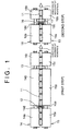
- the method according to the embodiment of the present invention includes quench-hardening including a first step, and a second step conducted after the first step.
- a hollow cylindrical workpiece 11 is quench-hardened from an outside surface.
- an entire cross-section of a wall of the workpiece 11 is subjected to induction-heating from the outside surface only to a temperature equal to or higher than an Ac 3 transformation temperature and equal to or less than a temperature 200°C higher than the Ac 3 transformation temperature, and preferably, to a temperature 50°C higher than the Ac 3 transformation temperature, at a heating portion (a heating coil 12).
- a frequency of an induction power source should be selected so that the entire cross-section of the wall is heated to the above-mentioned temperature.
- the reason why the workpiece 11 is continuously conveyed without a space between adjacent workpieces is to prevent heating energy from being taken by the tool for setting the workpiece due to removal of the tool, thereby to avoid a temporal stationary heating at an end portion in a longitudinal direction of the workpiece, which is required in the conventional methods. Due to this continuous heating, each workpiece can be heated uniformly in the longitudinal direction including the opposite end portions, so that a temperature difference caused in the longitudinal direction of the workpiece is effectively minimized.
- the reason why the workpiece 11 is conveyed in a horizontal direction is that if the workpiece 11 is continuously conveyed in a vertical direction, an apparatus will be necessarily too tall, which may cause inconvenience in its operation and a problem of an interference between the apparatus and a ceiling of a factory house in which the apparatus is installed.
- Conveying of the workpiece 11 is conducted as follows: The workpiece 11 is mounted on a pair of rotatory rollers 14 and 15 and is rotated about its axis by rotating rollers 14 and 15, one of which is slightly inclined downwardly with respect to a movement direction of the workpiece 11.
- the roller 14 is divided into a plurality of portions 14a, 14b, and 14c in the longitudinal direction, which are connected to each other by a shaft 14d so as to rotate integrally with each other.
- the roller 15 is divided into a plurality of portions 15a, 15b, and 15c in the longitudinal direction, which are connected to each other by a shaft 15d so as to rotate integrally with each other.
- the reason why the workpiece 11 is heated to a temperature equal to or above the Ac 3 transformation temperature is to austenitize a metal microstructure of the workpiece 11 for quench-hardening.
- an upper limit of a heating temperature is set at a temperature 200°C higher than the Ac 3 transformation temperature, and preferably, at a temperature 50°C higher than the Ac 3 transformation temperature is to ensure a necessary toughness at the entirety of the workpiece 11 by maintaining a crystal grain in the martensite microstructure generated during quench-hardening to be fine, so that even if cracks are generated in the surface of the workpiece during use, propagation of cracks is effectively suppressed. If the workpiece 11 were heated to a temperature exceeding the temperature 200°C higher than the Ac 3 transformation temperature, the crystal grain would become too coarse, thereby causing any crack generated in the surface during use to easily propagate to the entirety of the workpiece.
- the temperature of the workpiece 11 is made uniform in the longitudinal direction and in the thickness direction. With the lapse of time, the temperature of the workpiece is gradually lowered due to heat radiation of the workpiece 11.
- the workpiece 11 begins to be cooled at the cooling portion (by a coolant jetted out from the cooling jacket 13) before the temperature of the workpiece is lowered to an Ar 3 temperature.
- the workpiece 11 is cooled from the outside surface only and the entire cross-section of the wall of the workpiece 11 is quench-hardened. In this instance, since the entire cross-section of the wall is rapidly cooled from a temperature higher than the Ar 3 temperature, the workpiece 11 is quench-hardened through the entire cross-section of the wall.
- the entire cross-section of the wall of the workpiece 11 has a hardness of about HRC 56 and its metal microstructure is transformed into a martensite microstructure.
- the entire cross-section of the wall of the workpiece 11 is induction-heated to a temperature equal to or higher than the Ac 3 transformation temperature and equal to or lower than a temperature 200°C higher than the Ac 3 transformation temperature, and preferably, equal to or lower than a temperature 50°C higher than the Ac 3 transformation temperature.
- induction-heating is conducted only to the outside portion defined as a portion between the outside surface and a position spaced from the outside surface by a distance greater than one fourth of a thickness of the wall of the workpiece and smaller than one half of a thickness of the wall of the workpiece.
- rotating the workpiece 11 and conveying the workpiece 11 in the horizontal direction are conducted by mounting workpiece 11 on a pair of rotatory rollers 18 and 19, one of which is slightly inclined downwardly with respect to a movement direction of the workpiece.
- the roller 18 is divided into a plurality of portions 18a and 18b in the longitudinal direction, which are connected to each other by a shaft 18c so as to rotate integrally with each other.
- the roller 19 is divided into a plurality of portions 19a and 19b in the longitudinal direction, which are connected to each other by a shaft 19c so as to rotate integrally with each other.
- the reason why the upper limit of a heating temperature is set at a temperature 200°C higher than the Ac 3 transformation temperature, and preferably, at a temperature 50°C higher than Ac 3 transformation temperature is to maintain a crystal grain in the martensite microstructure at an outside portion of the workpiece generated during re-quench-hardening to be fine, so that cracks are effectively prevented from being generated during use, or even if cracks are generated, the cracks are hardly propagated.
- the core portion of the wall is at a temperature 400 - 700°C (a high-temperature tempering temperature)
- the inside portion is at a temperature lower than a low-temperature tempering temperature (i.e., before the heat energy is conducted from the outside portion to the inside portion so that a temperature of the inside portion reaches the low-temperature tempering temperature)
- the workpiece 11 is cooled by the coolant jetted out from the cooling jacket 17 from the outside surface only.
- the workpiece 11 Due to this cooling from the outside surface only, the workpiece 11 has an effective hardness at a first position located within the outside portion of the workpiece 11 which is defined as a portion located between the outside surface and a position spaced from the outside surface by a distance greater than one fourth of a thickness of the wall and less than one half of a thickness of the wall, a portion located between the first position having the effective hardness and the outside surface has a hardness greater than the effective hardness, and a portion located closer to the core portion than the first position having the effective hardness has a hardness less than the effective hardness.
- the workpiece 11 has an effective hardness at a second position located within the inside portion of the workpiece 11 which is defined as a portion located between the inside surface of the workpiece 11 and a position spaced from the inside surface by a distance less than one half of the thickness of the wall has the effective hardness, a portion located between the second position having the effective hardness and the inside surface has a hardness greater than the effective hardness, and a portion located closer to the core portion of the wall than the second position having the effective hardness has a hardness less than the effective hardness. That is, the core portion of the wall which is defined as a portion between the outside portion and the inside portion of the workpiece 11 is high-temperature tempered.
- the effective hardness means a hardness of the workpiece which is in a condition where 80% of the entire metal microstructure of the workpiece 11 is transformed into martensite microstructure.
- the effective hardness is determined by the carbon content of the workpiece.
- the carbon content of the workpiece 11 is 0.40% and the effective hardness is HRC 47.
- the hardness at the inside portion of the workpiece 11 gradually decreases from the inside surface toward the core portion of the wall. Since the inside portion of the workpiece 11 is not subjected to heating and cooling, neither the heating coil nor the water jacket needs to be inserted within the inside surface of the workpiece, so that the handling apparatus is unnecessary to be provided.
- the outside portion has a hardness of about HRC 56 by re-quench-hardening the outside portion.
- the core portion which has been heated to a temperature of 400 - 700°C during heating, is tempered at a high temperature and its metal microstructure is transformed into a sorbite microstructure having a hardness of about HRC 30 - 40, so that a necessary toughness is ensured to prevent cracks.
- the inside portion is cooled by cooling the workpiece from the outside surface only, the inside portion is cooled more slowly, compared with a case where the inside portion is cooled directly from the inside surface, so that deformation due to cooling (mainly generated in the longitudinal direction of the workpiece) is effectively suppressed, resulting that the magnitude of deviation in the dimension of the outside diameter is decreased compared with that in the conventional heat-treatment method.
- the workpiece 11 is tempered after the outside portion and the inside portion have been quench-hardened and the core portion has been quench-hardened and then high-temperature tempered due to quench-hardening including the first step and the second step.
- the above tempering may be conducted, or may be omitted.
- Heating during tempering is conducted by heating the workpiece within a furnace, or by induction-heating the workpiece from the outside surface of the workpiece only.
- uniform heating through the entire cross-section of the wall of the workpiece is easily realized.
- heating time is shortened and downsizing the equipment can be achieved.
- Tempering by heating the workpiece within a furnace may be a low-temperature tempering conducted at a temperature of 150 - 250°C or a high-temperature tempering conducted at a temperature of 400 - 700°C, which may be selected depending on quality requirements of the hollow cylindrical workpiece.
- low-temperature tempering the hardness obtained during quench-hardening is hardly decreased, and a necessary wear resistance is ensured.
- high-temperature tempering a good toughness is ensured.
- Tempering by induction-heating the workpiece may be a low-temperature tempering conducted at a temperature of 150 - 250°C or a high-temperature tempering conducted at a temperature of 400 - 700°C, which may be selected depending on the quality requirements of the hollow cylindrical workpiece.
- low-temperature tempering the hardness obtained during quench-hardening is hardly decreased, and a necessary wear resistance is ensured.
- high-temperature tempering a good toughness is ensured.
- tempering conducted after quench-hardening including the first step and the second step may be omitted, because with the low-carbon steel or the low-carbon low-alloy steel, the metal microstructure is unchanged and is maintained to be a low-carbon martensite microstructure even if tempering is conducted after quench-hardening.
- tempering was a low-temperature tempering tempered at a temperature equal to or lower than about 200°C. The tempering was conducted in batch process (about 2.5 Hr) by heating within a furnace.
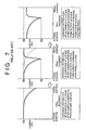
- the martensite microstructure obtained during the first and the second steps at the outside portion and at the inside portion was almost unchanged, and the hardness at the outside portion and the hardness at the inside portion were maintained (see a hardness distribution at the stage of quench-hardening of the outside portion ⁇ re-quench-hardening of the outside portion ⁇ tempering, of FIG. 5).
- the hardness at the stage after the tempering was about HRC 52 or greater.
- crush test was conducted and comparison was made between a conventional product heat-treated according to the method of Japanese Patent Publication SHO 59-77979 and a product heat-treated according to the above-described method of the present invention.
- Five test pieces were provided for the conventional product and the product heat-treated according to the method of the present invention, respectively.
- Table 1 shows the test results, crush loads at which the test pieces were crushed.
- the average values of the crush loads are the same with the conventional product and the product heat-treated according to the method of the present invention, which means that the product heat-treated according to the method of the present invention had a crush load equivalent to that of the conventional product.
Landscapes
- Chemical & Material Sciences (AREA)
- Engineering & Computer Science (AREA)
- Physics & Mathematics (AREA)
- Thermal Sciences (AREA)
- Crystallography & Structural Chemistry (AREA)
- Mechanical Engineering (AREA)
- Materials Engineering (AREA)
- Metallurgy (AREA)
- Organic Chemistry (AREA)
- Heat Treatment Of Articles (AREA)
Claims (10)
- Un procédé de durcissement par trempe d'une pièce cylindrique creuse (11), ladite pièce (11) présentant une surface extérieure et une surface intérieure définissant entre elles une paroi, ladite paroi présentant une partie extérieure définie entre ladite surface extérieure et une position espacée de ladite surface extérieure d'une distance supérieure à un quart de l'épaisseur de ladite paroi et inférieure à une moitié de l'épaisseur de ladite paroi, une partie intérieure définie entre ladite surface intérieure et une position espacée de ladite surface intérieure d'une distance inférieure à une moitié de l'épaisseur de ladite paroi, et une partie centrale définie entre ladite partie extérieure et ladite partie intérieure, ledit procédé comprenant les étapes consistant à :premièrement:transporter des pièces (11) les unes après les autres dans une direction sensiblement horizontale sans espace entre pièces voisines (11),chauffer par induction au niveau d'une partie de chauffage (12) une section transversale complète de ladite paroi de ladite pièce (11) simultanément avec ledit transport à une température égale ou supérieure à la température de transformation de Ac3 et égale ou inférieure à une température de 200°C plus élevée que ladite température de transformation de Ac3 uniquement depuis ladite surface extérieure de ladite pièce (11),rendre une température de ladite pièce (11) sensiblement uniforme dans une direction longitudinale et dans une direction de l'épaisseur de ladite pièce (11) en utilisant une période de temps nécessaire pour déplacer ladite pièce (11) vers une partie de refroidissement (13) espacée de ladite partie de chauffage (12), etrefroidir ladite pièce (11) uniquement depuis ladite surface extérieure, de sorte que la section transversale complète de ladite paroi de ladite pièce (11) soit durcie par trempe, ledit refroidissement étant initié avant que la température de ladite pièce (11) tombe à une température de Ar3;deuxièmement:transporter lesdites pièces (11) les unes après les autres, dont la section transversale complète de ladite paroi a été durcie par trempe, sans espace entre pièces voisines (11) dans une direction horizontale,chauffer par induction ladite partie extérieure de ladite paroi de ladite pièce (11) uniquement depuis la surface extérieure simultanément avec ledit transport de sorte que seulement la partie extérieure atteint une température égale ou supérieure à ladite température de transformation de Ac3 et égale ou inférieure à une température de 200°C plus élevée que ladite température de transformation de Ac3, etrefroidir ladite pièce (11) à l'intérieur d'une période de temps plus courte que 3 secondes après ledit chauffage uniquement depuis ladite surface extérieure de ladite pièce (11) et sans directement refroidir ladite partie intérieure depuis la surface intérieure, de sorte que (a) ladite pièce (11) présente une dureté effective au niveau d'une première position située à l'intérieur de ladite partie extérieure, (b) une partie située entre ladite première position et ladite surface extérieure présente une dureté supérieure à ladite dureté effective, et (c) une partie située plus près de ladite partie centrale que ladite première position présente une dureté inférieure à ladite dureté effective, alors que ladite pièce d'ouvrage (11) présente ladite dureté effective au niveau d'une seconde position située à l'intérieur de ladite partie intérieure, une partie entre ladite seconde position et ladite surface intérieure présente une dureté supérieure à ladite dureté effective, et une partie située plus près de ladite partie centrale que ladite seconde position présente une dureté inférieure à la dureté effective.
- Un procédé selon la revendication 1, dans lequel ladite pièce (11) est réalisée à partir d'au moins l'un parmi un acier au carbone et un acier faiblement allié au carbone, et dans lequel ledit procédé comprend en outre un revenu, effectué après lesdits second transport, chauffage et refroidissement.
- Un procédé selon la revendication 2, dans lequel ledit revenu comprend un chauffage à l'intérieur d'un four.
- Un procédé selon la revendication 3, dans lequel une température de chauffage pendant ledit chauffage à l'intérieur du four est dans la gamme de 150 à 250°C.
- Un procédé selon la revendication 3, dans lequel une température de chauffage pendant ledit chauffage à l'intérieur du four est dans la gamme de 400 à 700°C.
- Un procédé selon la revendication 2, dans lequel ledit revenu comprend un chauffage par induction effectué uniquement depuis ladite surface extérieure de ladite pièce.
- Un procédé selon la revendication 6, dans lequel une température de chauffage pendant ledit chauffage par induction est dans la gamme de 150 à 250°C.
- Un procédé selon la revendication 6, dans lequel une température de chauffage pendant ledit chauffage par induction est dans la gamme de 400 à 700°C.
- Un procédé selon la revendication 1, dans lequel ladite pièce (11) est réalisée à partir d'au moins l'un parmi un acier à bas carbone et un acier faiblement allié à bas carbone, et aucun revenu n'est effectué après lesdits seconds transport, chauffage et refroidissement.
- Un procédé selon la revendication 9, dans lequel ledit acier faiblement allié à bas carbone est réalisé à partir d'un acier au bore à bas carbone contenant de 0,05 à 0,30% de carbone en poids.
Applications Claiming Priority (6)
| Application Number | Priority Date | Filing Date | Title |
|---|---|---|---|
| JP1649298 | 1998-01-29 | ||
| JP1649298 | 1998-01-29 | ||
| JP36763998 | 1998-12-24 | ||
| JP36763998 | 1998-12-24 | ||
| JP00101099A JP4187334B2 (ja) | 1998-01-29 | 1999-01-06 | 中空円筒状ワークの熱処理方法 |
| JP101099 | 1999-01-06 |
Publications (3)
| Publication Number | Publication Date |
|---|---|
| EP0933437A2 EP0933437A2 (fr) | 1999-08-04 |
| EP0933437A3 EP0933437A3 (fr) | 2001-11-28 |
| EP0933437B1 true EP0933437B1 (fr) | 2005-07-27 |
Family
ID=27274722
Family Applications (1)
| Application Number | Title | Priority Date | Filing Date |
|---|---|---|---|
| EP99300696A Expired - Lifetime EP0933437B1 (fr) | 1998-01-29 | 1999-01-29 | Procédé de traitement thermique d'une pièce cylindrique creuse. |
Country Status (6)
| Country | Link |
|---|---|
| US (1) | US6179936B1 (fr) |
| EP (1) | EP0933437B1 (fr) |
| JP (1) | JP4187334B2 (fr) |
| KR (1) | KR100303166B1 (fr) |
| CN (1) | CN1100151C (fr) |
| DE (1) | DE69926272T2 (fr) |
Families Citing this family (25)
| Publication number | Priority date | Publication date | Assignee | Title |
|---|---|---|---|---|
| JP2001207216A (ja) * | 1999-11-18 | 2001-07-31 | Dai Ichi High Frequency Co Ltd | 金属円筒体の熱処理方法及び装置 |
| US7252721B2 (en) * | 2001-05-28 | 2007-08-07 | Ntn Corporation | Power transmission shaft |
| JP4169635B2 (ja) * | 2002-11-20 | 2008-10-22 | トピー工業株式会社 | 熱処理部材の部分熱処理方法 |
| KR100727754B1 (ko) * | 2006-03-14 | 2007-06-13 | 김봉수 | 스탬핑 금형의 펀치용 소재 열처리방법 |
| JP5424298B2 (ja) * | 2008-09-08 | 2014-02-26 | トピー工業株式会社 | 円柱状部品の熱処理方法 |
| JP5371084B2 (ja) * | 2007-11-12 | 2013-12-18 | トピー工業株式会社 | 円柱状部品の熱処理方法 |
| EP2224021A4 (fr) * | 2007-11-12 | 2013-09-11 | Topy Ind | Procédé de traitement thermique d'un composant basaltique |
| JP4676993B2 (ja) * | 2008-01-31 | 2011-04-27 | 津田金属熱煉工業株式会社 | ブッシュの製法 |
| DE112009000750B4 (de) * | 2008-03-31 | 2013-05-29 | Neturen Co. Ltd. | Stahlgegenstand, Verfahren zur Herstellung des Stahlgegenstands und Vorrichtung zur Herstellung eines Stahlgegenstands |
| EP2987873A3 (fr) * | 2009-07-22 | 2016-04-13 | NTN Corporation | Procédé de traitement thermique d'un élément en forme d'anneau, élément en forme d'anneau et son procédé de production, anneau de palier et son procédé de production, palier de roulement |
| WO2012002862A1 (fr) * | 2010-07-02 | 2012-01-05 | Aktiebolaget Skf | Composant mécanique et procédé de durcissement superficiel |
| CN103314119B (zh) | 2011-01-21 | 2015-09-02 | Ntn株式会社 | 套圈的制造方法、套圈及滚动轴承 |
| KR101311771B1 (ko) * | 2011-05-30 | 2013-09-25 | 현대제철 주식회사 | 소재의 가열방법 |
| WO2013008831A1 (fr) * | 2011-07-13 | 2013-01-17 | トピー工業株式会社 | Système de traitement thermique et procédé de traitement thermique |
| JP2013057092A (ja) * | 2011-09-07 | 2013-03-28 | Tsuda Heat Treatment Co Ltd | ブッシュの製造方法およびブッシュの熱処理装置 |
| DE102013100147B3 (de) * | 2013-01-09 | 2014-05-15 | Bochumer Eisenhütte Heintzmann GmbH & Co. KG | Verfahren zum Vergüten von Langmaterial |
| JP5629846B1 (ja) * | 2013-05-17 | 2014-11-26 | 株式会社小松製作所 | 履帯式足回り部品用鋼および履帯リンク |
| JP6436473B2 (ja) * | 2014-06-30 | 2018-12-12 | トピー工業株式会社 | 熱処理システムおよび熱処理方法 |
| CN106670745A (zh) * | 2016-12-29 | 2017-05-17 | 大连冶金工具厂有限公司 | 一种滚动轴承套圈加工工艺 |
| RU2723871C1 (ru) * | 2019-12-30 | 2020-06-17 | Акционерное общество "Чепецкий механический завод" | Способ безокислительной термической обработки изделий из аустенитной коррозионно-стойкой стали |
| US20210214815A1 (en) * | 2020-01-09 | 2021-07-15 | Progress Rail Services Corporation | Method of hardening manganese steel using ultrasonic impact treatment |
| CN111944978A (zh) * | 2020-08-13 | 2020-11-17 | 安徽鑫亿成精密机械有限公司 | 一种真空淬火炉 |
| KR102503739B1 (ko) * | 2021-06-11 | 2023-02-24 | 조진구 | 경사형 롤러를 구비한 고주파 열처리 시스템 |
| KR102447382B1 (ko) * | 2022-07-07 | 2022-09-23 | 정상석 | 성형 롤러의 차등 열처리 방법 |
| CN116121494B (zh) * | 2022-11-21 | 2025-09-09 | 石钢京诚装备技术有限公司 | 一种柱钉辊套的热处理方法 |
Family Cites Families (14)
| Publication number | Priority date | Publication date | Assignee | Title |
|---|---|---|---|---|
| DE2620377A1 (de) * | 1976-05-08 | 1977-11-17 | Aeg Elotherm Gmbh | Verfahren zur waermebehandlung von dickwandigen stahlroehren |
| US4210468A (en) * | 1978-08-17 | 1980-07-01 | Amsted Industries Incorporated | Piston pin and method for making such |
| JPS5977979A (ja) | 1982-10-15 | 1984-05-04 | Topy Ind Ltd | 履帯用ブツシングおよびその生産方法 |
| JP2572238B2 (ja) | 1987-09-18 | 1997-01-16 | 株式会社ネツレンヒラカタ | 小内径筒体の内外周表面焼入れ方法 |
| EP0339152B1 (fr) * | 1988-04-28 | 1993-08-11 | Topy Industries, Limited | Procédé de traitement thermique de douilles pour patins de chenille de tracteurs chenillés |
| JPH0270022A (ja) * | 1988-09-05 | 1990-03-08 | Topy Ind Ltd | 無限軌道車輌用の履帯に使用されるブッシュの熱処理方法 |
| JPH03285020A (ja) * | 1990-03-31 | 1991-12-16 | Topy Ind Ltd | 履帯用ブッシングの製造方法 |
| RU1770401C (ru) * | 1990-06-27 | 1992-10-23 | Специальное Конструкторское Бюро Научно-Производственного Объединения "Геотехника" | Способ непрерывно-последовательной индукционной обработки бурильной трубы |
| JPH0578746A (ja) * | 1991-09-25 | 1993-03-30 | Topy Ind Ltd | 履帯用ブツシングの製造方法 |
| JPH0578745A (ja) * | 1991-09-25 | 1993-03-30 | Topy Ind Ltd | 履帯用ブツシングの製造方法 |
| JP2672441B2 (ja) * | 1992-12-10 | 1997-11-05 | 新日本製鐵株式会社 | 耐ssc性の優れた高強度高靭性シームレス鋼管の製造法 |
| US5249868A (en) * | 1993-01-27 | 1993-10-05 | Caterpillar Inc. | Track bushing |
| JPH07299997A (ja) | 1994-05-09 | 1995-11-14 | Bando Chem Ind Ltd | 転写フィルム |
| JP3880086B2 (ja) | 1995-11-17 | 2007-02-14 | トピー工業株式会社 | 円筒状ワークの熱処理方法 |
-
1999
- 1999-01-06 JP JP00101099A patent/JP4187334B2/ja not_active Expired - Fee Related
- 1999-01-26 KR KR1019990002414A patent/KR100303166B1/ko not_active Expired - Fee Related
- 1999-01-28 US US09/238,610 patent/US6179936B1/en not_active Expired - Lifetime
- 1999-01-28 CN CN99101603A patent/CN1100151C/zh not_active Expired - Fee Related
- 1999-01-29 EP EP99300696A patent/EP0933437B1/fr not_active Expired - Lifetime
- 1999-01-29 DE DE69926272T patent/DE69926272T2/de not_active Expired - Lifetime
Also Published As
| Publication number | Publication date |
|---|---|
| EP0933437A3 (fr) | 2001-11-28 |
| CN1100151C (zh) | 2003-01-29 |
| KR100303166B1 (ko) | 2001-09-13 |
| JP4187334B2 (ja) | 2008-11-26 |
| EP0933437A2 (fr) | 1999-08-04 |
| DE69926272D1 (de) | 2005-09-01 |
| JP2000239744A (ja) | 2000-09-05 |
| CN1224765A (zh) | 1999-08-04 |
| DE69926272T2 (de) | 2006-05-24 |
| KR19990068141A (ko) | 1999-08-25 |
| US6179936B1 (en) | 2001-01-30 |
Similar Documents
| Publication | Publication Date | Title |
|---|---|---|
| EP0933437B1 (fr) | Procédé de traitement thermique d'une pièce cylindrique creuse. | |
| EP3715478B1 (fr) | Fil machine pour frappe à froid, produit traité l'utilisant et procédé de fabrication associé | |
| EP0700739B1 (fr) | Procédé pour la production de maillons de chaínes de roulement pour véhicules | |
| US7827842B2 (en) | Hot forging facility | |
| CN101660036A (zh) | 一种高强高韧性钢管热处理的方法 | |
| CN111002000B (zh) | 一种提高谐波减速器柔轮晶粒度的加工方法 | |
| KR20200076797A (ko) | 강도 편차가 적은 열연 소둔 강판, 부재 및 이들의 제조방법 | |
| JP4219023B2 (ja) | 高強度ドライブシャフトとその製造方法 | |
| CN105369015A (zh) | 一种42CrMo轴类零件淬火热处理工艺 | |
| EP1897961A1 (fr) | Produits forgés à chaud excellents de par leur résistance à la fatigue, leur procédé de fabrication et pièces structurelles de machine | |
| JPH09241749A (ja) | 高周波焼入方法 | |
| JP2001098326A (ja) | 履帯用ブッシングとその製造方法 | |
| JP4061003B2 (ja) | 高周波焼入れ性と冷鍛性に優れた冷間鍛造用棒線材 | |
| US5049207A (en) | Heat treatment process for bushing used in track of endless track tractor | |
| JP3880086B2 (ja) | 円筒状ワークの熱処理方法 | |
| JP2008512614A (ja) | ジョイント用焼入れ保持器 | |
| JPH09143567A (ja) | 高強度鋼管の製造方法 | |
| US6294031B1 (en) | Production method of a heat-treated steel member | |
| JP3747982B2 (ja) | 中・高炭素鋼板の製造方法 | |
| JP3966210B2 (ja) | 熱間圧延ままで球状化炭化物および黒鉛組織を有する機械構造用鋼の製造方法 | |
| JPH11279647A (ja) | 円筒状ワークの焼もどし方法 | |
| US5342457A (en) | Method for the production of a switch diamond | |
| KR100257648B1 (ko) | 고강도 임팩트바아의 제조방법 | |
| JPH09235620A (ja) | 高周波焼入方法 | |
| JP2005002366A (ja) | 冷間加工性に優れた高硬度高周波焼入れ用鋼 |
Legal Events
| Date | Code | Title | Description |
|---|---|---|---|
| PUAI | Public reference made under article 153(3) epc to a published international application that has entered the european phase |
Free format text: ORIGINAL CODE: 0009012 |
|
| 17P | Request for examination filed |
Effective date: 19990218 |
|
| AK | Designated contracting states |
Kind code of ref document: A2 Designated state(s): AT BE CH CY DE DK ES FI FR GB GR IE IT LI LU MC NL PT SE Kind code of ref document: A2 Designated state(s): DE FR GB IT |
|
| AX | Request for extension of the european patent |
Free format text: AL;LT;LV;MK;RO;SI |
|
| PUAL | Search report despatched |
Free format text: ORIGINAL CODE: 0009013 |
|
| AK | Designated contracting states |
Kind code of ref document: A3 Designated state(s): AT BE CH CY DE DK ES FI FR GB GR IE IT LI LU MC NL PT SE |
|
| AX | Request for extension of the european patent |
Free format text: AL;LT;LV;MK;RO;SI |
|
| AKX | Designation fees paid |
Free format text: DE FR GB IT |
|
| 17Q | First examination report despatched |
Effective date: 20030604 |
|
| GRAP | Despatch of communication of intention to grant a patent |
Free format text: ORIGINAL CODE: EPIDOSNIGR1 |
|
| GRAS | Grant fee paid |
Free format text: ORIGINAL CODE: EPIDOSNIGR3 |
|
| GRAA | (expected) grant |
Free format text: ORIGINAL CODE: 0009210 |
|
| AK | Designated contracting states |
Kind code of ref document: B1 Designated state(s): DE FR GB IT |
|
| REG | Reference to a national code |
Ref country code: GB Ref legal event code: FG4D |
|
| REF | Corresponds to: |
Ref document number: 69926272 Country of ref document: DE Date of ref document: 20050901 Kind code of ref document: P |
|
| ET | Fr: translation filed | ||
| PLBE | No opposition filed within time limit |
Free format text: ORIGINAL CODE: 0009261 |
|
| STAA | Information on the status of an ep patent application or granted ep patent |
Free format text: STATUS: NO OPPOSITION FILED WITHIN TIME LIMIT |
|
| 26N | No opposition filed |
Effective date: 20060428 |
|
| PGFP | Annual fee paid to national office [announced via postgrant information from national office to epo] |
Ref country code: DE Payment date: 20110126 Year of fee payment: 13 |
|
| PGFP | Annual fee paid to national office [announced via postgrant information from national office to epo] |
Ref country code: GB Payment date: 20110120 Year of fee payment: 13 |
|
| GBPC | Gb: european patent ceased through non-payment of renewal fee |
Effective date: 20120129 |
|
| PG25 | Lapsed in a contracting state [announced via postgrant information from national office to epo] |
Ref country code: GB Free format text: LAPSE BECAUSE OF NON-PAYMENT OF DUE FEES Effective date: 20120129 Ref country code: DE Free format text: LAPSE BECAUSE OF NON-PAYMENT OF DUE FEES Effective date: 20120801 |
|
| REG | Reference to a national code |
Ref country code: DE Ref legal event code: R119 Ref document number: 69926272 Country of ref document: DE Effective date: 20120801 |
|
| REG | Reference to a national code |
Ref country code: FR Ref legal event code: PLFP Year of fee payment: 18 |
|
| REG | Reference to a national code |
Ref country code: FR Ref legal event code: PLFP Year of fee payment: 19 |
|
| PGFP | Annual fee paid to national office [announced via postgrant information from national office to epo] |
Ref country code: FR Payment date: 20170125 Year of fee payment: 19 |
|
| PGFP | Annual fee paid to national office [announced via postgrant information from national office to epo] |
Ref country code: IT Payment date: 20170130 Year of fee payment: 19 |
|
| PG25 | Lapsed in a contracting state [announced via postgrant information from national office to epo] |
Ref country code: FR Free format text: LAPSE BECAUSE OF NON-PAYMENT OF DUE FEES Effective date: 20180131 |
|
| REG | Reference to a national code |
Ref country code: FR Ref legal event code: ST Effective date: 20180928 |
|
| PG25 | Lapsed in a contracting state [announced via postgrant information from national office to epo] |
Ref country code: IT Free format text: LAPSE BECAUSE OF NON-PAYMENT OF DUE FEES Effective date: 20180129 |