EP0933470A2 - Concentrateur par essorage - Google Patents
Concentrateur par essorage Download PDFInfo
- Publication number
- EP0933470A2 EP0933470A2 EP99300799A EP99300799A EP0933470A2 EP 0933470 A2 EP0933470 A2 EP 0933470A2 EP 99300799 A EP99300799 A EP 99300799A EP 99300799 A EP99300799 A EP 99300799A EP 0933470 A2 EP0933470 A2 EP 0933470A2
- Authority
- EP
- European Patent Office
- Prior art keywords
- screen
- stock
- strainer
- concentrator
- paddles
- Prior art date
- Legal status (The legal status is an assumption and is not a legal conclusion. Google has not performed a legal analysis and makes no representation as to the accuracy of the status listed.)
- Withdrawn
Links
- 238000000034 method Methods 0.000 claims description 12
- 230000007423 decrease Effects 0.000 claims description 4
- 239000002002 slurry Substances 0.000 description 37
- XLYOFNOQVPJJNP-UHFFFAOYSA-N water Substances O XLYOFNOQVPJJNP-UHFFFAOYSA-N 0.000 description 7
- 239000000725 suspension Substances 0.000 description 6
- 229920001131 Pulp (paper) Polymers 0.000 description 5
- 239000011148 porous material Substances 0.000 description 5
- 239000011343 solid material Substances 0.000 description 5
- 239000007788 liquid Substances 0.000 description 4
- 239000002562 thickening agent Substances 0.000 description 4
- 239000012141 concentrate Substances 0.000 description 3
- 239000013055 pulp slurry Substances 0.000 description 3
- 239000007787 solid Substances 0.000 description 3
- 239000010893 paper waste Substances 0.000 description 2
- 230000001154 acute effect Effects 0.000 description 1
- 230000015572 biosynthetic process Effects 0.000 description 1
- 238000010276 construction Methods 0.000 description 1
- 230000018044 dehydration Effects 0.000 description 1
- 238000006297 dehydration reaction Methods 0.000 description 1
- 230000001419 dependent effect Effects 0.000 description 1
- 238000007599 discharging Methods 0.000 description 1
- 230000000694 effects Effects 0.000 description 1
- 238000013467 fragmentation Methods 0.000 description 1
- 238000006062 fragmentation reaction Methods 0.000 description 1
- 239000002440 industrial waste Substances 0.000 description 1
- 238000009434 installation Methods 0.000 description 1
- 239000011550 stock solution Substances 0.000 description 1
- 238000011144 upstream manufacturing Methods 0.000 description 1
Images


Classifications
-
- D—TEXTILES; PAPER
- D21—PAPER-MAKING; PRODUCTION OF CELLULOSE
- D21F—PAPER-MAKING MACHINES; METHODS OF PRODUCING PAPER THEREON
- D21F1/00—Wet end of machines for making continuous webs of paper
- D21F1/66—Pulp catching, de-watering, or recovering; Re-use of pulp-water
- D21F1/74—Pulp catching, de-watering, or recovering; Re-use of pulp-water using cylinders
-
- B—PERFORMING OPERATIONS; TRANSPORTING
- B01—PHYSICAL OR CHEMICAL PROCESSES OR APPARATUS IN GENERAL
- B01D—SEPARATION
- B01D33/00—Filters with filtering elements which move during the filtering operation
- B01D33/06—Filters with filtering elements which move during the filtering operation with rotary cylindrical filtering surfaces, e.g. hollow drums
- B01D33/11—Filters with filtering elements which move during the filtering operation with rotary cylindrical filtering surfaces, e.g. hollow drums arranged for outward flow filtration
-
- B—PERFORMING OPERATIONS; TRANSPORTING
- B01—PHYSICAL OR CHEMICAL PROCESSES OR APPARATUS IN GENERAL
- B01D—SEPARATION
- B01D33/00—Filters with filtering elements which move during the filtering operation
- B01D33/44—Regenerating the filter material in the filter
- B01D33/46—Regenerating the filter material in the filter by scrapers, brushes nozzles or the like acting on the cake-side of the filtering element
- B01D33/466—Regenerating the filter material in the filter by scrapers, brushes nozzles or the like acting on the cake-side of the filtering element scrapers
-
- D—TEXTILES; PAPER
- D21—PAPER-MAKING; PRODUCTION OF CELLULOSE
- D21F—PAPER-MAKING MACHINES; METHODS OF PRODUCING PAPER THEREON
- D21F1/00—Wet end of machines for making continuous webs of paper
- D21F1/66—Pulp catching, de-watering, or recovering; Re-use of pulp-water
Definitions
- the present invention relates to a dewatering concentrator for concentrating waste paper pulp slurry, that is to say separating waste paper pulp slurry or other industrial waste slurry into moisture and solid components or into a moisture component and concentrated stock.
- Centrifugal separators utilising centrifugal force are a known type of dewatering concentrator. This type of concentrator applies a high centrifugal force to a suspension containing solid components to remove moisture or water components through a strainer. The resultant dewatered stock is discharged by a screw which scrapes the stock off the inner surface of the strainer.
- the screw thickener mentioned above can not achieve sufficient dewatering unless the stock to be processed has a concentration of, for example, 2.5% or more.
- solid components tend to mix into the stock solution after squeezing since the strainer cannot be provided with pores with a diameter smaller than a predetermined value, e.g. 2 mm in diameter.
- the drive for the separator must be very robust since a sufficient dewatering effect cannot be attained unless the centrifugal force applied to the stock is 1000 G or more.
- the fibres of the pulp stock tend to become entangled with each other to form a thick stock mat which may rotate together with the screw, resulting in failure of smooth discharge of the dewatered stock.
- the axial shaft within the screen is thus connected, in use, to drive means arranged to rotate it about its length and the screen is also connected, in use, to drive means arranged to rotate it about its axis at a different speed.
- the screen and the shaft rotate at different speeds.
- the paddles carried by the shaft extend to close to the screen, that is to say to within about 0.1 to 5.0 mm, and thus scrape off the stock mat which tends to form on the internal surface of the screen.
- the paddles are preferably so constructed that they impart an axial force to the stock within the screen to move it in the direction towards the outlet.
- the paddles are preferably so constructed that the speed of movement of the stock decreases along the length of the screen in the direction towards the outlet.
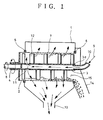
- Figures 1, 2 and 3 are schematic axial sectional views of first, second and third embodiments of the invention, respectively.
- Figure 1 shows a dewatering separator which comprises a casing 1, a hollow cylindrical strainer 2 which is supported at two axially spaced positions for rotation in the casing 1, and a hollow pipe 3, which is mounted in the strainer 2 for rotation at a speed different to that of the strainer 2.
- the strainer 2 has a closed end integral with a hollow outer shaft 4. The other end of the strainer 2 is open and constitutes an outlet 15.
- the strainer 2 is supported on the casing 1 by a bearing 5 near the closed end of the strainer 2 and by a bearing 6 at the open end of the strainer 2.
- the strainer 2 has, at its outer periphery, a screen 7 with pores or slits of a size which are appropriate to the properties of the stock to be concentrated and/or the quality of the liquid after squeezing.
- the hollow pipe 3 has a closed end adjacent the closed end of the strainer 2 integral with an inner shaft 8 which extends through the outer shaft 4.
- the other end of the hollow pipe 3 is open to provide an opening 3a to which a slurry inlet 10 is rotatably connected for the introduction of the slurry 9.
- the hollow pipe 3 further has radial slurry outlets 11 adjacent its closed end for discharging the slurry 9 outwardly into the interior of the strainer 2.
- the hollow pipe 3 has a plurality of axially spaced plate-like paddles 12 mounted on the outer periphery of the pipe 3 whose length is such that there is a gap of about 0.1-5.0 mm between the tips of the paddles 12 and the inner surface of the screen 7.
- the paddles 12 are tilted or inclined to the axis of the pipe 3 so as to move the stock from the closed end of the strainer 2 toward the outlet 15 (i.e. from left to right in Figure 1).
- the maximum tilt angle of the paddles 12 to the axis of the pipe 3 is 90 degrees, at which angle the paddles cannot move the stock at all in the axial direction.
- the paddles 12 are arranged to have small or acute tilt angles to the axis of the pipe 3 so as to move the slurry 9 rapidly in the axial direction and to prevent thick stock mat from being formed on the inner surface of the screen 7.
- the paddles 12 are arranged to have progressively increasing tilt angles closer to 90 degrees so that the axial velocity of the slurry gradually decreases as its moisture content decreases.
- the paddles 12 serve to maintain the pores or slits of the screen 7 clear and to pulverise the sheet-like stock mat which forms on the screen 7.
- the casing 1 is integrally formed at its lower end with a tapered water discharge duct 13 so that water or moisture components produced as the result of dewatering through the screen 7, i.e. water components passing through the screen 7, are collected together and discharged to the exterior.
- the casing 1 is also integrally formed with a stock outlet 14 which communicates with the outlet 15 to discharge solid material or concentrated stock, after dewatering.
- the hollow pipe 3 and the inner shaft 8 are supported on the casing 1 or the strainer 2 by bearings.
- the slurry 9 to be dewatered is introduced through the slurry inlet 10 into the hollow pipe 3 and is discharged through the slurry outlets 11 in the hollow pipe 3 into the interior of the strainer 2 which is rotated via the outer shaft 4 by an external drive (not shown) to rotate the slurry and thus apply centrifugal force to it. As a result, the slurry 9 is pressed against the inner surface of the screen 7 and is dewatered.
- the slurry 9 In the initial stage of the dewatering process the slurry 9 has the highest water content. If the moisture is removed quickly in this stage, the fluidity of the slurry might be lost, resulting in the formation of a thick, cylindrical stock mat on the screen 7. Such a thick stock mat would rotate in unison with the paddles 12 around the inner surface of the screen 7, leading to inadequate dewatering and of discharge of the stock mat.
- the stock mat is gradually scraped off in the form of flakes and is fluidised by the tips of the paddles 12 before the mat becomes thick.
- the slurry 9 immediately after the slurry 19 is supplied through the slurry outlets 11 to the interior of the strainer 2 in the initial stage of the dewatering process, the slurry 9 has a high moisture content and has a certain fluidity. In this stage, the slurry 9 is quickly moved downstream by the paddles 12 with the smaller tilt angles so that a thick stock mat can not form on the inner surface of the strainer 2 and dewatering by centrifugal force can be effected to the full extent.
- the slurry 9 is moved by the paddles 12 toward the outlet 15.
- the moisture content of the slurry is reduced and its fluidity is also reduced.
- the sheet-like stock mat formed on the inner surface of the screen 7 is scraped off by the paddles 12 into flakes before the mat becomes thick. Fragmentation into flakes will contribute to an increase in fluidity, resulting in an increase of mobility.
- the tilt angles of the paddles 12 progressively increase in the downstream direction to reduce the speed of movement of the slurry. As a result, the flake-like solid material is dewatered to the maximum extent and then discharged through the stock outlet 14.
- the slurry 9 is moved at a relatively high velocity by the paddles 12 installed at relatively small tilt angles so that a thick stock mat is prevented from being formed.
- the slurry 9 is slowly dewatered whilst being moved at a slower velocity by the paddles 12 installed at larger tilt angles and the stock mat which is formed is scraped off by the paddles 12 into flakes and is fluidised.
- effective dewatering can be carried out over the entire area of the strainer 2.
- the slurry 9 is thus dewatered into concentrated form or solid material, and is discharged to the exterior through the stock outlet 14.
- the moisture or water components obtained as a result of the dewatering are discharged through the moisture discharge duct 13.
- a thin stock mat is formed on the inner surface of the screen 7 in the initial stage of dewatering and dewatering is effectively performed. Further, the stock mat is pulverised to flakes by the paddles 12 in the later stages of the dewatering process and is moved slowly. Thus, the dewatered stock is not rotated in unison with the paddles 12 and is discharged smoothly. There is no need to reduce the thickness of the entire stock mat. As a result, the dewatering efficiency per unit area of the strainer 2 is increased, which contributes to making the apparatus very compact. Also, the hollow pipe 3 serves to introduce the stock to be dewatered (slurry 9) into the strainer 2 and to rotate the paddles 12, which represents a further simplification and further reduction in size of the apparatus.
- Figure 2 shows a second embodiment of the invention which is similar to the first embodiment shown in Figure 1 except that the strainer 2 is frustoconical and converges toward the open end 15 (in the direction of movement of the stock) and that the paddles 12 are of different length matching the shape of the strainer 2.
- the slurry 9 is moved by the paddles 12 and dewatering by the rotating strainer 2 is enhanced to a maximum level.
- Figure 3 shows a third embodiment of the invention in which the strainer 2 is again frustoconical but divergent towards the outlet 15. With this construction it is easier to discharge the stock or concentrated slurry after dewatering.
- this apparatus is suitable for rapid dewatering of slurry of a type which can be easily dewatered.
Landscapes
- Chemical & Material Sciences (AREA)
- Chemical Kinetics & Catalysis (AREA)
- Centrifugal Separators (AREA)
- Treatment Of Sludge (AREA)
- Paper (AREA)
- Filtration Of Liquid (AREA)
Applications Claiming Priority (2)
| Application Number | Priority Date | Filing Date | Title |
|---|---|---|---|
| JP2200998 | 1998-02-03 | ||
| JP10022009A JPH11216313A (ja) | 1998-02-03 | 1998-02-03 | 脱水濃縮装置 |
Publications (2)
| Publication Number | Publication Date |
|---|---|
| EP0933470A2 true EP0933470A2 (fr) | 1999-08-04 |
| EP0933470A3 EP0933470A3 (fr) | 2000-05-17 |
Family
ID=12071014
Family Applications (1)
| Application Number | Title | Priority Date | Filing Date |
|---|---|---|---|
| EP99300799A Withdrawn EP0933470A3 (fr) | 1998-02-03 | 1999-02-03 | Concentrateur par essorage |
Country Status (9)
| Country | Link |
|---|---|
| US (1) | US6261417B1 (fr) |
| EP (1) | EP0933470A3 (fr) |
| JP (1) | JPH11216313A (fr) |
| KR (1) | KR100325283B1 (fr) |
| CN (1) | CN1236841A (fr) |
| BR (1) | BR9900515A (fr) |
| CA (1) | CA2260643A1 (fr) |
| ID (1) | ID22087A (fr) |
| TW (1) | TW444079B (fr) |
Cited By (4)
| Publication number | Priority date | Publication date | Assignee | Title |
|---|---|---|---|---|
| WO2004007835A3 (fr) * | 2002-07-12 | 2006-09-14 | Whitewater Solutions Corp | Systeme permettant de separer une matiere portee par un fluide dudit fluide qui transporte en plus de ladite matiere des particules |
| WO2009137452A3 (fr) * | 2008-05-05 | 2010-04-01 | Fluid-Quip, Inc. | Appareil et procédé pour filtrer un matériau dans un milieu liquide |
| CN101027447B (zh) * | 2002-07-12 | 2010-08-11 | 怀特-沃特索鲁申斯公司 | 从承载颗粒物和液载材料的流体中分离该液载材料的系统 |
| WO2014037187A1 (fr) * | 2012-09-06 | 2014-03-13 | Siemens Vai Metals Technologies Gmbh | Dispositif d'essorage de boue |
Families Citing this family (23)
| Publication number | Priority date | Publication date | Assignee | Title |
|---|---|---|---|---|
| DE19616623B4 (de) * | 1996-04-25 | 2004-12-23 | Der Grüne Punkt - Duales System Deutschland Ag | Vorrichtung zur Trennung von zähelastischen Materialien wie Kunststoffen und von unter mechanischer Beanspruchung zerfasernden Stoffen wie Papier |
| EP1057533A1 (fr) * | 1999-05-27 | 2000-12-06 | Ferrum AG | Centrifugeuse |
| US6517432B1 (en) | 2000-03-21 | 2003-02-11 | Wms Gaming Inc. | Gaming machine with moving symbols on symbol array |
| KR20020024757A (ko) * | 2000-09-26 | 2002-04-01 | 장완수 | 폐수의 잔존물 분리장치 |
| JP3720816B2 (ja) * | 2003-04-01 | 2005-11-30 | 栄工機株式会社 | ドラム形紙料精選スクリーン |
| US7490672B2 (en) * | 2005-09-09 | 2009-02-17 | Baker Hughes Incorporated | System and method for processing drilling cuttings during offshore drilling |
| KR100688887B1 (ko) | 2006-03-31 | 2007-03-02 | 한국생산기술연구원 | 슬러지의 탈수 전처리를 수행하기 위한 수직 왕복 구동식스크린 세정 장치를 구비하는 밀폐형 농축기 |
| DE102007025540B3 (de) * | 2007-05-31 | 2009-01-02 | Eichelmann, Larissa | Filtervorrichtung zum Filtern von Flüssigkeiten |
| US20090325678A1 (en) * | 2008-06-25 | 2009-12-31 | Wms Gaming Inc. | Wagering system with expanding wild feature dictated by direction indicator |
| JP6141589B2 (ja) * | 2011-09-27 | 2017-06-07 | 株式会社タクマ | 回転ドラム式濃縮システム |
| US9073088B2 (en) * | 2012-04-17 | 2015-07-07 | Otis Walton | Centrifugal size-separation sieve for granular materials |
| CN105817069A (zh) * | 2016-05-31 | 2016-08-03 | 上海迈正环境科技有限公司 | 一种餐厨垃圾脱水除渣装置 |
| CN107940225B (zh) * | 2017-12-02 | 2020-08-18 | 徐州新南湖科技有限公司 | 一种汽车机油滤清器前置过滤装置 |
| CN108554008A (zh) * | 2018-05-17 | 2018-09-21 | 珠海市万顺睿通科技有限公司 | 一种水处理装置 |
| CN109489351A (zh) * | 2018-12-19 | 2019-03-19 | 南京金弓厨具设备有限公司 | 一种厨余垃圾脱水提升机 |
| CN109663800A (zh) * | 2019-01-13 | 2019-04-23 | 南京宜玖厨具工程有限公司 | 脱水机 |
| CN112062305B (zh) * | 2020-09-04 | 2022-11-08 | 贵州工程应用技术学院 | 一种煤样和岩石试样加工实验室废水处理系统 |
| CN112973830A (zh) * | 2021-02-23 | 2021-06-18 | 殷明根 | 一种面粉加工原料处理系统 |
| CN112791497B (zh) * | 2021-04-09 | 2021-07-16 | 东营联合石化有限责任公司 | 一种用于加氢裂化反应器的过滤装置 |
| CN113499630B (zh) * | 2021-07-09 | 2022-03-29 | 中远关西涂料化工(天津)有限公司 | 一种聚氨酯水性涂料制备工艺 |
| JP7844009B2 (ja) * | 2022-10-18 | 2026-04-13 | 株式会社大善 | 含水繊維系原料濃縮機 |
| CN116477732B (zh) * | 2023-05-17 | 2024-06-04 | 巨灵(南京)智能科技有限公司 | 一种印花废水快速处理中心 |
| CN120622640B (zh) * | 2025-08-13 | 2025-11-21 | 山西三建集团有限公司 | 一种建筑施工的可回收型降水回收系统 |
Family Cites Families (13)
| Publication number | Priority date | Publication date | Assignee | Title |
|---|---|---|---|---|
| US2943800A (en) | 1954-11-13 | 1960-07-05 | Wultsch Ferdinand | Highly effective device for wet-separation |
| US3270663A (en) | 1964-11-30 | 1966-09-06 | Beloit Corp | Screen plate for pulp press and the like |
| US3585924A (en) * | 1969-03-10 | 1971-06-22 | William J Nolan | Apparatus for the removal of liquids from fibrous materials |
| US3970548A (en) * | 1973-08-27 | 1976-07-20 | The Black Clawson Company | Apparatus for screening paper fiber stock |
| FR2540094B1 (fr) * | 1983-02-02 | 1986-01-03 | Erpac | Perfectionnement aux epaississeurs de boues a vis |
| US4518621A (en) * | 1983-06-02 | 1985-05-21 | Brown International Corporation | Method and apparatus for finishing juices from fruits and vegetables and the like |
| DE3624536A1 (de) * | 1986-07-19 | 1988-01-21 | Kloeckner Humboldt Deutz Ag | Schneckenzentrifuge |
| JP2597147B2 (ja) | 1988-06-20 | 1997-04-02 | 相川鉄工株式会社 | 製紙用スクリュープレス |
| SE463425B (sv) | 1989-04-17 | 1990-11-19 | Sunds Defibrator Ind Ab | Avvattningsanordning |
| FR2666997B2 (fr) | 1990-01-31 | 1993-09-03 | Pain Creation | Appareil de pressurage. |
| JPH0763873B2 (ja) * | 1991-12-20 | 1995-07-12 | 富国工業株式会社 | 回転篩 |
| ATE205266T1 (de) | 1995-07-17 | 2001-09-15 | Kvaerner Pulping Tech | Verfahren zur behandlung eines papierzellstoffes und vorrichtung dafür |
| DE19717448A1 (de) | 1997-04-25 | 1997-10-02 | Peter Dr Lueth | Vorrichtung und Filtrationsverfahren zur Abtrennung von Stoffen aus Suspensionen |
-
1998
- 1998-02-03 JP JP10022009A patent/JPH11216313A/ja active Pending
-
1999
- 1999-01-26 TW TW088101126A patent/TW444079B/zh active
- 1999-01-28 US US09/238,642 patent/US6261417B1/en not_active Expired - Fee Related
- 1999-02-02 KR KR1019990003322A patent/KR100325283B1/ko not_active Expired - Fee Related
- 1999-02-02 CA CA002260643A patent/CA2260643A1/fr not_active Abandoned
- 1999-02-02 ID IDP990072D patent/ID22087A/id unknown
- 1999-02-03 CN CN99100771A patent/CN1236841A/zh active Pending
- 1999-02-03 EP EP99300799A patent/EP0933470A3/fr not_active Withdrawn
- 1999-02-03 BR BR9900515-8A patent/BR9900515A/pt not_active IP Right Cessation
Cited By (5)
| Publication number | Priority date | Publication date | Assignee | Title |
|---|---|---|---|---|
| WO2004007835A3 (fr) * | 2002-07-12 | 2006-09-14 | Whitewater Solutions Corp | Systeme permettant de separer une matiere portee par un fluide dudit fluide qui transporte en plus de ladite matiere des particules |
| CN101027447B (zh) * | 2002-07-12 | 2010-08-11 | 怀特-沃特索鲁申斯公司 | 从承载颗粒物和液载材料的流体中分离该液载材料的系统 |
| WO2009137452A3 (fr) * | 2008-05-05 | 2010-04-01 | Fluid-Quip, Inc. | Appareil et procédé pour filtrer un matériau dans un milieu liquide |
| US8813973B2 (en) | 2008-05-05 | 2014-08-26 | Fluid-Quip, Inc. | Apparatus and method for filtering a material from a liquid medium |
| WO2014037187A1 (fr) * | 2012-09-06 | 2014-03-13 | Siemens Vai Metals Technologies Gmbh | Dispositif d'essorage de boue |
Also Published As
| Publication number | Publication date |
|---|---|
| EP0933470A3 (fr) | 2000-05-17 |
| CN1236841A (zh) | 1999-12-01 |
| KR100325283B1 (ko) | 2002-02-21 |
| KR19990072358A (ko) | 1999-09-27 |
| BR9900515A (pt) | 2001-03-20 |
| US6261417B1 (en) | 2001-07-17 |
| CA2260643A1 (fr) | 1999-08-03 |
| ID22087A (id) | 1999-09-02 |
| JPH11216313A (ja) | 1999-08-10 |
| TW444079B (en) | 2001-07-01 |
Similar Documents
| Publication | Publication Date | Title |
|---|---|---|
| EP0933470A2 (fr) | Concentrateur par essorage | |
| US6723205B1 (en) | Degassing centrifugal apparatus with energy recovery, process for degassing a fluid and process for producing paper or board | |
| JP5191565B2 (ja) | 遠心脱水方法及び遠心脱水装置 | |
| US20010001457A1 (en) | Methods and apparatus for de-watering sludge | |
| US6193643B1 (en) | Decantation centrifuge with peripheral washing nozzles | |
| JPH02502171A (ja) | 被処理材を脱水し絞り出しするための方法および装置 | |
| JPH0242951B2 (fr) | ||
| JP6751564B2 (ja) | 遠心分離機 | |
| FI117711B (fi) | Menetelmä ja laitteisto materiaalien tai materiaaliseosten käsittelemiseksi | |
| US4447320A (en) | Device for cleaning and recovering paper pulp | |
| JPH0784717B2 (ja) | リジエクト減少装置を備えた選別装置 | |
| US4202773A (en) | Apparatus for the dewatering of sludge | |
| FI120913B (fi) | Laite massan lajittelemiseksi | |
| EP0202223B1 (fr) | Appareil pour epaissir et raffiner des suspensions de pulpe de fibres | |
| KR20250070228A (ko) | 탈수효과 증대를 위한 슬러지 이동공간 확보형 원심분리장치 | |
| JPH01189358A (ja) | デカンタ型遠心分離機を用いる汚泥の脱水方法及び装置 | |
| JP2001029842A (ja) | 遠心脱水装置 | |
| CA2033920A1 (fr) | Appareil pour l'epaississement de suspensions de fibres | |
| WO1993022062A1 (fr) | Centrifugeuse de decantation | |
| JP3997128B2 (ja) | 遠心分離装置 | |
| JP2000237630A (ja) | 遠心脱水装置 | |
| JPH067936B2 (ja) | デカンタ型遠心分離機の遠心力作用域でのスラッジ脱水装置 | |
| JP2000271510A (ja) | 遠心脱水装置 | |
| JPS6321993Y2 (fr) | ||
| JP2000210591A (ja) | 遠心脱水装置 |
Legal Events
| Date | Code | Title | Description |
|---|---|---|---|
| PUAI | Public reference made under article 153(3) epc to a published international application that has entered the european phase |
Free format text: ORIGINAL CODE: 0009012 |
|
| AK | Designated contracting states |
Kind code of ref document: A2 Designated state(s): DE FI FR GB SE |
|
| AX | Request for extension of the european patent |
Free format text: AL;LT;LV;MK;RO;SI |
|
| PUAL | Search report despatched |
Free format text: ORIGINAL CODE: 0009013 |
|
| AK | Designated contracting states |
Kind code of ref document: A3 Designated state(s): AT BE CH CY DE DK ES FI FR GB GR IE IT LI LU MC NL PT SE |
|
| AX | Request for extension of the european patent |
Free format text: AL;LT;LV;MK;RO;SI |
|
| RIC1 | Information provided on ipc code assigned before grant |
Free format text: 7D 21F 1/66 A, 7D 21F 1/74 B |
|
| 17P | Request for examination filed |
Effective date: 20000911 |
|
| AKX | Designation fees paid |
Free format text: DE FI FR GB SE |
|
| 17Q | First examination report despatched |
Effective date: 20021010 |
|
| GRAH | Despatch of communication of intention to grant a patent |
Free format text: ORIGINAL CODE: EPIDOS IGRA |
|
| STAA | Information on the status of an ep patent application or granted ep patent |
Free format text: STATUS: THE APPLICATION IS DEEMED TO BE WITHDRAWN |
|
| 18D | Application deemed to be withdrawn |
Effective date: 20030812 |