EP0933483A2 - Elément de construction pour l'isolation thermique - Google Patents
Elément de construction pour l'isolation thermique Download PDFInfo
- Publication number
- EP0933483A2 EP0933483A2 EP98123421A EP98123421A EP0933483A2 EP 0933483 A2 EP0933483 A2 EP 0933483A2 EP 98123421 A EP98123421 A EP 98123421A EP 98123421 A EP98123421 A EP 98123421A EP 0933483 A2 EP0933483 A2 EP 0933483A2
- Authority
- EP
- European Patent Office
- Prior art keywords
- support element
- component according
- transverse force
- pressure
- force rod
- Prior art date
- Legal status (The legal status is an assumption and is not a legal conclusion. Google has not performed a legal analysis and makes no representation as to the accuracy of the status listed.)
- Granted
Links
- 238000010276 construction Methods 0.000 title 1
- 238000005452 bending Methods 0.000 claims abstract description 6
- 238000009413 insulation Methods 0.000 claims description 15
- 230000005540 biological transmission Effects 0.000 claims description 8
- 230000002787 reinforcement Effects 0.000 description 11
- 239000012212 insulator Substances 0.000 description 4
- 230000006835 compression Effects 0.000 description 2
- 238000007906 compression Methods 0.000 description 2
- 238000003780 insertion Methods 0.000 description 2
- 230000037431 insertion Effects 0.000 description 2
- 238000004901 spalling Methods 0.000 description 2
- 238000004873 anchoring Methods 0.000 description 1
- 238000009434 installation Methods 0.000 description 1
- 239000000463 material Substances 0.000 description 1
- 230000003014 reinforcing effect Effects 0.000 description 1
- 230000000284 resting effect Effects 0.000 description 1
Images




Classifications
-
- E—FIXED CONSTRUCTIONS
- E04—BUILDING
- E04B—GENERAL BUILDING CONSTRUCTIONS; WALLS, e.g. PARTITIONS; ROOFS; FLOORS; CEILINGS; INSULATION OR OTHER PROTECTION OF BUILDINGS
- E04B1/00—Constructions in general; Structures which are not restricted either to walls, e.g. partitions, or floors or ceilings or roofs
- E04B1/003—Balconies; Decks
- E04B1/0038—Anchoring devices specially adapted therefor with means for preventing cold bridging
Definitions
- the invention relates to a component for thermal insulation between two Components, especially between a building and a cantilever Outer part, consisting of an insulating body to be laid between them with at least one pressure element and a shear bar, the each run through the insulating body transversely to the longitudinal extent thereof, wherein the pressure element via terminal pressure plates in There is an operative connection with both components, and the transverse force rod starting from the building side diagonally from top to bottom through the Insulator runs through and protrudes on both sides into the components.
- the present invention is based on the object, the To improve shear bars in terms of installation conditions, thereby the component for thermal insulation even easier to install design without, on the other hand, reducing the Transverse forces induce transversal forces.
- the component for thermal insulation one to be concreted in the area of the projecting outer part Support element has that the support element for mutual force-transmitting support on a section of the transverse force rod rests, and that the transverse force rod in the area of the cantilever Angled upwards after passing under the support element and runs in the direction of the train zone.
- the support element enables the appropriate positioning not only a backing in the bending area of the shear force of the shear force rod, but above all leads the force-transmitting connection with the transverse force rod in an advantageous manner that the force passed from the support element into the lateral force rod and then up into the Tensile zone is transmitted, causing the spalling of the concrete in the addressed Area of the highly deformed shear bar is avoided.
- transverse force rod with the support element is particularly advantageous is positively connected, that is, not just vertically, but also in a horizontal direction transverse to the direction of extension of the transverse force rod forces can be transmitted in the direction, whereby the advantages according to the invention can be further improved.
- the support element is part of one with two components that are operatively connected to transmit pressure force, horizontally extending through the insulating body pressure element is formed, namely in particular from one terminal to the Printing element cited printing plate, which in most applications to be arranged in the area of the bent shear bar anyway is.
- the support element can also be spaced apart arranged by the pressure element in the projecting outer part and for better Position fixation must be connected to at least two shear bars.
- the preferred direction of extension of the support element parallel to the longitudinal extent of the insulating body ie in the horizontal direction perpendicular to that formed by each shear bar Level.
- shear bar Pressure plate traversed in the area of its horizontal center to thereby to get a symmetrical power distribution or transmission that is free of additional horizontal transverse forces.
- the underpass not only the lower pressure plate area means, but also consist of crossing the pressure plate can be in a higher area of the pressure plate, which is the power transmission still favored.
- the pressure plate can have a recess for crossing of the transverse force rod, which either enclosed on all sides and is adapted to the cross section of the transverse force rod and so the Form-fit with the shear force rod, or the particular after is open at the bottom, so that the vertical insertion of the pressure plate and Allow shear bar.
- the positive connection could in in this case take place via a locking connection, the pressure plate then surrounds the lateral force rod on the side and on its upper side and after the insertion.
- connection points towards a material connection Connection such as a welded joint has the advantage that it is much easier to assemble with the same power transmission, which is particularly important when the components for thermal insulation are finally assembled affects.
- Compression bars can consist of, for example, a deformed Flat bar with a corresponding recess for crossing the Shear force through the pressure element.
- This flat bar can at least be provided at one end with a pressure plate through at least an immediately formed approximately vertically extending bend is formed is.
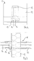
- FIG. 1 shows a component according to the invention for thermal insulation 1, that between a building (to be arranged on the right in FIG. 1) and a building projecting outer part (to be arranged on the left in FIG. 1) becomes.
- a building to be arranged on the right in FIG. 1
- a building projecting outer part to be arranged on the left in FIG. 1 becomes.
- it has an extending between the two components Insulating body 2 and arranged transversely to the longitudinal extent of the insulating body Pressure elements 3, shear bars 4 and 5 tension bars.
- This Reinforcement elements protrude from the insulating body 2 and are consequently anchored in the concrete of the respective adjacent component.
- the pressure elements 3 are made a flat bar formed, the terminal pressure plates 6, the are formed by vertical turns of the flat bar.
- the printing elements protrude slightly into the adjacent concrete components.
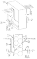
- FIGS. 4 to 7 An alternative embodiment is shown in FIGS. 4 to 7, in which a component 11 for thermal insulation is shown, which consists of an insulating body 12, tension rods 13, transverse force rods 14 and pressure elements 15 consists.
- a support element 16 is provided, which is not is formed from parts of the printing elements, but from a separate one Rod section, which in the horizontal direction parallel to the longitudinal extension of the Insulator runs.
- This support element 16 is in the region of its ends on two spaced apart pressure elements 15 supported while it in the area of the horizontal center on the bent area of the Shear bar 14 is. This touches the concrete of support element and transverse force rod for the above Advantages of the improved power transmission on the one hand and the better Bendability of the shear bar without flaking of the concrete in the bent area on the other hand.
- the variant of a component 31 shown in FIGS. 12 to 15 with an insulating body 32, tension rods 33, transverse force rods 34 and one Support element 36 differs from this embodiment from Figures 4 to 7 only in that the support element is not like the rod section 16 has a cylindrical shape, but only semi-cylindrical is formed, with its rounded outer surface in the bend of two spaced-apart transverse force bars 34 rests, while the flat outer surface is oriented horizontally is and thereby a better contact surface for absorbing force from the cantilever Offers outer part on the support element.
- Support element from Figures 12 to 15 regardless of pressure elements arranged.
- FIGS. 8 to 11 there is a component 21 for thermal insulation from an insulating body 22, tension rods 23, Shear bars 24 and pressure elements 25, the two terminal Pressure rod 26 connecting pressure plates 27 acts as a support element, by being traversed by the transverse force rod 24. Since the pressure rod 26 runs exactly perpendicular to the longitudinal extension of the insulating body, must the shear force rod for this - as can best be seen from FIG. 10 - one have lateral offset, which makes it from the top of the Insulator coming out on one side of the pressure rod runs below, passes under it on the underside and then on the other Side up again vertically into the train zone. This extends in the building assigned to the building and in the insulating body extending section of the shear bar in a plane that is parallel to the plane in which the section assigned to the projecting component of the shear force runs.
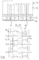
- FIGS. 16 to 19 finally show an exemplary embodiment of a Component 41 for thermal insulation, in which a support element 46 applied a total of three shear bars 44 and this from one common printing plate for four printing elements 45 there. It should be noted that the support element 46 in the form of the common Pressure plate can also extend over the entire length of the component is usually 100 cm.
- the support element 46 has cutouts 48 in the lower region, through which the transverse force bars 44 with their traversing the support element Extend sections, the recesses 48 a the Have bar diameter of the transverse force bars adapted width and hereby a positive connection between the support element and Enable shear bars.
Landscapes
- Engineering & Computer Science (AREA)
- Architecture (AREA)
- Physics & Mathematics (AREA)
- Electromagnetism (AREA)
- Civil Engineering (AREA)
- Structural Engineering (AREA)
- Thermal Insulation (AREA)
- Building Environments (AREA)
- Reinforcement Elements For Buildings (AREA)
- Macromolecular Compounds Obtained By Forming Nitrogen-Containing Linkages In General (AREA)
- Insulated Conductors (AREA)
Applications Claiming Priority (2)
| Application Number | Priority Date | Filing Date | Title |
|---|---|---|---|
| DE19804038A DE19804038A1 (de) | 1998-02-03 | 1998-02-03 | Bauelement zur Wärmedämmung |
| DE19804038 | 1998-02-03 |
Publications (3)
| Publication Number | Publication Date |
|---|---|
| EP0933483A2 true EP0933483A2 (fr) | 1999-08-04 |
| EP0933483A3 EP0933483A3 (fr) | 2000-04-19 |
| EP0933483B1 EP0933483B1 (fr) | 2003-04-02 |
Family
ID=7856407
Family Applications (1)
| Application Number | Title | Priority Date | Filing Date |
|---|---|---|---|
| EP98123421A Expired - Lifetime EP0933483B1 (fr) | 1998-02-03 | 1998-12-09 | Elément de construction pour l'isolation thermique |
Country Status (3)
| Country | Link |
|---|---|
| EP (1) | EP0933483B1 (fr) |
| AT (1) | ATE236307T1 (fr) |
| DE (2) | DE19804038A1 (fr) |
Cited By (5)
| Publication number | Priority date | Publication date | Assignee | Title |
|---|---|---|---|---|
| EP2610410A3 (fr) * | 2011-12-30 | 2014-03-05 | SCHÖCK BAUTEILE GmbH | Elément de construction pour l'isolation thermique |
| DE202016103344U1 (de) | 2016-06-23 | 2016-08-01 | Max Frank Gmbh & Co. Kg | Anschlusselement für lasteinleitende Bauteile |
| DE202016103345U1 (de) | 2016-06-23 | 2016-08-01 | Max Frank Gmbh & Co. Kg | Anschlusselement für lasteinleitende Bauteile |
| EP3611310A1 (fr) * | 2018-08-15 | 2020-02-19 | H-Bau Technik GmbH | Ancre de garde-corps |
| CN114837307A (zh) * | 2021-02-01 | 2022-08-02 | 力维拓有限责任公司 | 将承受载荷的第二建筑件附加地连结到第一建筑件的装置 |
Family Cites Families (9)
| Publication number | Priority date | Publication date | Assignee | Title |
|---|---|---|---|---|
| ATE38069T1 (de) * | 1984-01-13 | 1988-11-15 | Pawe Ag | Kragplattenanschlusselement. |
| DE3542467A1 (de) * | 1985-11-30 | 1987-06-04 | Camino Handelsgesellschaft Mbh | Bausatz fuer eine stahlbeton-konsole zum abfangen eines verblendmauerwerks |
| AT396151B (de) * | 1987-03-11 | 1993-06-25 | Avi Alpenlaendische Vered | Anschlusselement fuer kragplatten sowie aus mehreren anschlusselementen zusammengesetztes anschlusselement |
| DE4102332C2 (de) * | 1991-01-26 | 1998-07-02 | Frank Gmbh & Co Kg Max | Balkonanschluß |
| DE4302683A1 (de) * | 1993-02-01 | 1994-08-04 | Schoeck Bauteile Gmbh | Bauelement zur Wärmedämmung bei Gebäuden |
| DE4302682A1 (de) * | 1993-02-01 | 1994-08-04 | Schoeck Bauteile Gmbh | Bauelement zur Wärmedämmung |
| AT964U1 (de) * | 1994-10-31 | 1996-08-26 | Hako Bautechnik Ges M B H | Wärmedämmendes anschlussstück |
| DE19508292A1 (de) * | 1995-03-09 | 1996-09-12 | Rolf Hirn | Bauelement zur Wärmedämmung von Gebäuden |
| DE29615018U1 (de) * | 1996-08-29 | 1996-12-05 | Eisenhofer, André, Dipl.-Ing. (FH), 86150 Augsburg | Vorrichtung zur gemeinsamen Aufnahme von Druck- und Querkräften |
-
1998
- 1998-02-03 DE DE19804038A patent/DE19804038A1/de not_active Withdrawn
- 1998-12-09 AT AT98123421T patent/ATE236307T1/de active
- 1998-12-09 EP EP98123421A patent/EP0933483B1/fr not_active Expired - Lifetime
- 1998-12-09 DE DE59807734T patent/DE59807734D1/de not_active Expired - Lifetime
Non-Patent Citations (1)
| Title |
|---|
| None |
Cited By (5)
| Publication number | Priority date | Publication date | Assignee | Title |
|---|---|---|---|---|
| EP2610410A3 (fr) * | 2011-12-30 | 2014-03-05 | SCHÖCK BAUTEILE GmbH | Elément de construction pour l'isolation thermique |
| DE202016103344U1 (de) | 2016-06-23 | 2016-08-01 | Max Frank Gmbh & Co. Kg | Anschlusselement für lasteinleitende Bauteile |
| DE202016103345U1 (de) | 2016-06-23 | 2016-08-01 | Max Frank Gmbh & Co. Kg | Anschlusselement für lasteinleitende Bauteile |
| EP3611310A1 (fr) * | 2018-08-15 | 2020-02-19 | H-Bau Technik GmbH | Ancre de garde-corps |
| CN114837307A (zh) * | 2021-02-01 | 2022-08-02 | 力维拓有限责任公司 | 将承受载荷的第二建筑件附加地连结到第一建筑件的装置 |
Also Published As
| Publication number | Publication date |
|---|---|
| ATE236307T1 (de) | 2003-04-15 |
| EP0933483A3 (fr) | 2000-04-19 |
| DE19804038A1 (de) | 1999-08-05 |
| DE59807734D1 (de) | 2003-05-08 |
| EP0933483B1 (fr) | 2003-04-02 |
Similar Documents
| Publication | Publication Date | Title |
|---|---|---|
| DE2702750C3 (de) | Gleitschuh für die Spanneinrichtung einer Gnfcenverbmivorrichtung | |
| EP0295685A1 (fr) | Dispositif de fixation de rails de chemin de fer sur voie rigide | |
| DE2731898A1 (de) | Wandkonstruktion | |
| EP2003011A2 (fr) | Système de réglage de rails pour un siège de véhicule automobile | |
| DE3422905A1 (de) | Vorrichtung zum verbinden einer balkonplatte und einer geschossdecke | |
| EP0750076B1 (fr) | Elément de construction pour isolation thermique | |
| DE102016102133A1 (de) | Achseinheit | |
| EP0933483B1 (fr) | Elément de construction pour l'isolation thermique | |
| CH678204A5 (fr) | ||
| EP0831183B1 (fr) | Elément de construction pour isolation thermique | |
| WO1999028570A1 (fr) | Piece d'accouplement | |
| EP1031668B1 (fr) | Elément de construction pour l'isolation thermique | |
| DE19908388A1 (de) | Bauelement zur Wärmedämmung | |
| EP0834622B1 (fr) | Liaison isolée thermiquement entre éléments extérieurs en béton, en particulier en porte-à-faux, et bâtiment | |
| DE2412381C3 (de) | Befestigungsanordnung für Begrenzungstafeln in Form eines Gitters | |
| EP1072729B1 (fr) | Pièce de construction comme élément de connection entre deux parties de bâtiment | |
| DE69516395T2 (de) | Verankerungsvorrichtung für einen träger | |
| DE19722028B4 (de) | Bauelement zur Wärmedämmung | |
| DE102006032444A1 (de) | Bauelement zur Wärmedämmung | |
| EP0133875A1 (fr) | Elément de construction isolant thermique pour bâtiments | |
| EP0049431A2 (fr) | Faux-plafond à résilles | |
| EP1932978B1 (fr) | Elément d'armature pour l'absorption de forces dans des plaques de béton dans la zone d'éléments d'appui | |
| EP2080841B1 (fr) | Elément de pose de dalles en console | |
| EP0353560A1 (fr) | Espaceur pour armatures de béton | |
| DE29808491U1 (de) | Bewehrungselement für Schubbewehrungen |
Legal Events
| Date | Code | Title | Description |
|---|---|---|---|
| PUAI | Public reference made under article 153(3) epc to a published international application that has entered the european phase |
Free format text: ORIGINAL CODE: 0009012 |
|
| AK | Designated contracting states |
Kind code of ref document: A2 Designated state(s): AT BE CH DE FR LI NL |
|
| AX | Request for extension of the european patent |
Free format text: AL;LT;LV;MK;RO;SI |
|
| PUAL | Search report despatched |
Free format text: ORIGINAL CODE: 0009013 |
|
| AK | Designated contracting states |
Kind code of ref document: A3 Designated state(s): AT BE CH CY DE DK ES FI FR GB GR IE IT LI LU MC NL PT SE |
|
| AX | Request for extension of the european patent |
Free format text: AL;LT;LV;MK;RO;SI |
|
| 17P | Request for examination filed |
Effective date: 20000607 |
|
| AKX | Designation fees paid |
Free format text: AT BE CH DE FR LI NL |
|
| GRAH | Despatch of communication of intention to grant a patent |
Free format text: ORIGINAL CODE: EPIDOS IGRA |
|
| GRAH | Despatch of communication of intention to grant a patent |
Free format text: ORIGINAL CODE: EPIDOS IGRA |
|
| GRAA | (expected) grant |
Free format text: ORIGINAL CODE: 0009210 |
|
| AK | Designated contracting states |
Designated state(s): AT BE CH DE FR LI NL |
|
| REG | Reference to a national code |
Ref country code: CH Ref legal event code: EP |
|
| REG | Reference to a national code |
Ref country code: CH Ref legal event code: NV Representative=s name: R. A. EGLI & CO. PATENTANWAELTE |
|
| REF | Corresponds to: |
Ref document number: 59807734 Country of ref document: DE Date of ref document: 20030508 Kind code of ref document: P |
|
| ET | Fr: translation filed | ||
| PLBE | No opposition filed within time limit |
Free format text: ORIGINAL CODE: 0009261 |
|
| STAA | Information on the status of an ep patent application or granted ep patent |
Free format text: STATUS: NO OPPOSITION FILED WITHIN TIME LIMIT |
|
| 26N | No opposition filed |
Effective date: 20040105 |
|
| PGFP | Annual fee paid to national office [announced via postgrant information from national office to epo] |
Ref country code: AT Payment date: 20131216 Year of fee payment: 16 Ref country code: DE Payment date: 20131217 Year of fee payment: 16 Ref country code: CH Payment date: 20131218 Year of fee payment: 16 |
|
| PGFP | Annual fee paid to national office [announced via postgrant information from national office to epo] |
Ref country code: NL Payment date: 20131216 Year of fee payment: 16 |
|
| REG | Reference to a national code |
Ref country code: DE Ref legal event code: R119 Ref document number: 59807734 Country of ref document: DE |
|
| REG | Reference to a national code |
Ref country code: NL Ref legal event code: V1 Effective date: 20150701 |
|
| REG | Reference to a national code |
Ref country code: NL Ref legal event code: V1 Effective date: 20150701 |
|
| REG | Reference to a national code |
Ref country code: CH Ref legal event code: PL |
|
| REG | Reference to a national code |
Ref country code: AT Ref legal event code: MM01 Ref document number: 236307 Country of ref document: AT Kind code of ref document: T Effective date: 20141209 |
|
| PG25 | Lapsed in a contracting state [announced via postgrant information from national office to epo] |
Ref country code: NL Free format text: LAPSE BECAUSE OF NON-PAYMENT OF DUE FEES Effective date: 20150701 |
|
| PG25 | Lapsed in a contracting state [announced via postgrant information from national office to epo] |
Ref country code: CH Free format text: LAPSE BECAUSE OF NON-PAYMENT OF DUE FEES Effective date: 20141231 Ref country code: DE Free format text: LAPSE BECAUSE OF NON-PAYMENT OF DUE FEES Effective date: 20150701 Ref country code: LI Free format text: LAPSE BECAUSE OF NON-PAYMENT OF DUE FEES Effective date: 20141231 |
|
| PG25 | Lapsed in a contracting state [announced via postgrant information from national office to epo] |
Ref country code: AT Free format text: LAPSE BECAUSE OF NON-PAYMENT OF DUE FEES Effective date: 20141209 |
|
| REG | Reference to a national code |
Ref country code: FR Ref legal event code: PLFP Year of fee payment: 18 |
|
| PGFP | Annual fee paid to national office [announced via postgrant information from national office to epo] |
Ref country code: BE Payment date: 20151221 Year of fee payment: 18 Ref country code: FR Payment date: 20151218 Year of fee payment: 18 |
|
| PG25 | Lapsed in a contracting state [announced via postgrant information from national office to epo] |
Ref country code: BE Free format text: LAPSE BECAUSE OF NON-PAYMENT OF DUE FEES Effective date: 20161231 |
|
| REG | Reference to a national code |
Ref country code: FR Ref legal event code: ST Effective date: 20170831 |
|
| PG25 | Lapsed in a contracting state [announced via postgrant information from national office to epo] |
Ref country code: FR Free format text: LAPSE BECAUSE OF NON-PAYMENT OF DUE FEES Effective date: 20170102 |
|
| REG | Reference to a national code |
Ref country code: BE Ref legal event code: MM Effective date: 20161231 |