EP0933497A2 - Outil de forage - Google Patents
Outil de forage Download PDFInfo
- Publication number
- EP0933497A2 EP0933497A2 EP99100208A EP99100208A EP0933497A2 EP 0933497 A2 EP0933497 A2 EP 0933497A2 EP 99100208 A EP99100208 A EP 99100208A EP 99100208 A EP99100208 A EP 99100208A EP 0933497 A2 EP0933497 A2 EP 0933497A2
- Authority
- EP
- European Patent Office
- Prior art keywords
- drill
- helix
- drilling
- drilling tool
- cutting
- Prior art date
- Legal status (The legal status is an assumption and is not a legal conclusion. Google has not performed a legal analysis and makes no representation as to the accuracy of the status listed.)
- Granted
Links
Images

Classifications
-
- E—FIXED CONSTRUCTIONS
- E21—EARTH OR ROCK DRILLING; MINING
- E21B—EARTH OR ROCK DRILLING; OBTAINING OIL, GAS, WATER, SOLUBLE OR MELTABLE MATERIALS OR A SLURRY OF MINERALS FROM WELLS
- E21B10/00—Drill bits
- E21B10/44—Bits with helical conveying portion, e.g. screw type bits; Augers with leading portion or with detachable parts
-
- E—FIXED CONSTRUCTIONS
- E21—EARTH OR ROCK DRILLING; MINING
- E21B—EARTH OR ROCK DRILLING; OBTAINING OIL, GAS, WATER, SOLUBLE OR MELTABLE MATERIALS OR A SLURRY OF MINERALS FROM WELLS
- E21B10/00—Drill bits
- E21B10/02—Core bits
- E21B10/04—Core bits with core destroying means
Definitions
- the invention relates to a drilling tool, in particular a Earth boring tool, according to the preamble of claim 1.
- Such a drilling tool in particular an earth drilling tool, has a drill shaft formed coaxially to an axis of rotation on which at least one drill helix is arranged which is at its end pointing in the feed direction has a cutting device, which is essentially extends radially to the axis of rotation.
- Such drilling tools usually have one so-called pilots. It is a center cutting edge, which is the guidance of the tool during the drilling process serves.
- this center cutting edge must have different soil formations be adjusted and thus for a hole be replaced when the soil type or soil formation changes. They also have center cutting edges high wear. You turn at the same angular velocity as the whole Drilling tool. Because of their small radial expansion however, they also move about the axis of rotation, opposite outer areas of the drilling tool, significantly reduced Circumferential speed on the material to be drilled.
- the invention has for its object to provide a drilling tool that is characterized by low wear and good guidance during drilling.
- This object is achieved in that the essentially radially extending cutting device for Form a cutting-free center radially from the axis of rotation is spaced that the cutting device in the feed direction protrudes from the knife-free center and that the cutting-free center with a to Axis of rotation is provided at an inclined deflection surface, which is used to derive a drill core that forms during drilling formed in a conveying area of the drill helix is.
- a key concept of the invention can therefore be seen in that by dispensing with a center cutting edge centric drill core is formed during drilling. From one the core meets the deflecting surface and is directed by this into the production area of the drill helix. A wear-prone pilot who is for a straight forward Propulsion of the drilling tool is no longer necessary required. The drilling tool is guided by the supports forming drill core.
- a particularly quiet and straightforward propulsion of the drilling tool is achieved in that two coils with a cutting device are provided that the Cutting devices are constructed essentially the same and that the cutters are at an angle of approximately Are arranged 180 ° to each other. Basically more cutting devices can also be provided, for example three or four.
- a light and inexpensive embodiment of the subject matter of the invention is achieved in that the drill coils have different dimensions in the axial direction. This means that several cutting edges are available for the drilling process. To promote the drilling material from the borehole however, only a few coils or a single coil educated.
- At least two Drill coils only along a first drill coil an axial portion of the drill shaft extends, while a second helix substantially along the entire drill shaft is formed.
- this embodiment by promoting the drilling material along the entire length of the drilling tool with a single drill helix out.
- the first drill helix exclusively at the end of the drill shaft pointing in the feed direction is formed and that the first helix is not has more than one turn. This can reduce the weight of the drilling tool can be further reduced while the second drill helix to convey the drilling material in one wide area takes over.
- An advantageous further development of the subject matter of the invention is characterized in that by the deflecting surface the drill core that forms can be derived into an intermediate space, that between the first drill helix and the second drill helix is formed.
- the drill core is thus turned into a flow of cuttings between the first drill helix and the second Drill helix derived. This will make it faster and reliable removal of the distracted and broken off Part of the drill core ensured.
- the deflection surface be a free-form surface is trained. So it is possible to change the flow behavior of the drill core as it moves along the Deflection surface as well as when it enters the area to influence the drilling coils positively.
- the lowest possible friction due to the deflected core is achieved according to the invention in that the deflecting surface about as a portion of a helical shape Surface is designed.
- the weight of the drilling tool can still be thereby reduce that the drill shaft is tubular, that the baffle at least partially on an insert is molded and that the insert firmly with the tubular Shaft is connectable.
- This use of a so-called Soul tube allows the installation easily replaceable Calls. It is so easy to adapt to different ones Floor conditions possible.
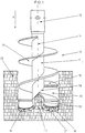
- An earth drilling tool 10 shown in Figure 1 is already partly in a feed direction A into a floor 23 advanced.
- a first drill helix 12 and a second Drill helix 13 coaxially wind around a cylindrical one Drill shaft 11.
- the rotary movement about an axis of rotation 14 and a feed movement of the earth drilling tool is from a Drive device not shown in FIG a fastening device 15 on the earth drilling tool 10 transfer.
- These cutters 16 are opposite the axis of rotation 14 of the earth drilling tool 10 radially spaced so that the earth drilling tool 10 has a center 17 free of cutting edges.
- a drill core 19 which is supported by a drill shaft 11 Deflection surface 18 attached obliquely to the axis of rotation 14 into a Conveyed area 20 between the coils 12 and 13 deflected becomes.
- a smooth running of the earth drilling tool 10 is ensured that the two cutting devices 16 in are essentially symmetrical to the axis of rotation 14, and the first drill helix 12 more than half a turn has the axis of rotation 14.
- the cutting geometries are approximate symmetrical, but not the radial distances between the teeth 21 from the axis of rotation 14. By a radial offset of the opposite teeth will be even over the radius Cutting performance achieved.
- the drilling coils 12 and 13 thus remove drilling material from the Working area of the cutting devices 16.
- the drilling material over the entire conveying area of the drilling tool 10 is transported, the drillings only a small amount from the first helix 12 Conveyed height to then from the second drill helix 13 to be transported further.
- the drill core 19 is directed from the deflecting surface 18 kinked, broken off or on the second drill helix 13 distracted.
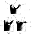
- FIGS. An insert 30 is shown schematically in FIGS. on which the deflection surface is a free-form surface 31 is trained.
- This insert 30 is fixed with a tubular Connected shaft, also known as the soul tube becomes.
- the insert 30 has essentially the shape of a Axis of rotation 14 coaxial cylinders.
- the free-form surface 31 educated. It forms two, approximately opposite one another Outbreaks 32 and 33 of different sizes in the Lateral surface of the cylinder.
- the free-form surface 31 is in the essentially as a gutter with an arched bottom line designed between the outbreaks 32 and 33.
- the direction of rotation corresponds to the bottom line the direction of rotation of the coils and the Inclination of the bottom line with respect to the axis of rotation 14 runs steadily.
- V-grooves 35 There is a channel wall on each side of the channel provided which is the same height in the axial direction have and their main cutting ends flattened are. In each of these main cutting ends a rectified V-groove 35 is formed, the V-grooves 35 arranged substantially diametrically opposite are.
- the V-grooves 35 of course, too be designed as differently shaped grooves or several grooves can, for fastening the insert 30 in the soul tube or serve to accommodate the cutting devices.
- the fixation of the insert 30, on the high torque act takes place in that the radially inner ends of the Engage the cutting devices in the V-grooves 35 in a form-fitting manner.
- An opening 36 formed in the freeform surface 31 enables it, rinsing or cooling liquids in the area to introduce the free-form surface 31.
Landscapes
- Engineering & Computer Science (AREA)
- Geology (AREA)
- Mining & Mineral Resources (AREA)
- Life Sciences & Earth Sciences (AREA)
- General Life Sciences & Earth Sciences (AREA)
- Fluid Mechanics (AREA)
- Environmental & Geological Engineering (AREA)
- Physics & Mathematics (AREA)
- Mechanical Engineering (AREA)
- Geochemistry & Mineralogy (AREA)
- Earth Drilling (AREA)
- Processing Of Stones Or Stones Resemblance Materials (AREA)
- Surgical Instruments (AREA)
- Saccharide Compounds (AREA)
- Steroid Compounds (AREA)
- Drilling Tools (AREA)
- Cutting Tools, Boring Holders, And Turrets (AREA)
- Drilling And Boring (AREA)
Applications Claiming Priority (2)
| Application Number | Priority Date | Filing Date | Title |
|---|---|---|---|
| DE29801700U DE29801700U1 (de) | 1998-02-02 | 1998-02-02 | Bohrwerkzeug |
| DE29801700U | 1998-02-02 |
Publications (3)
| Publication Number | Publication Date |
|---|---|
| EP0933497A2 true EP0933497A2 (fr) | 1999-08-04 |
| EP0933497A3 EP0933497A3 (fr) | 2000-07-12 |
| EP0933497B1 EP0933497B1 (fr) | 2003-08-20 |
Family
ID=8052069
Family Applications (1)
| Application Number | Title | Priority Date | Filing Date |
|---|---|---|---|
| EP99100208A Expired - Lifetime EP0933497B1 (fr) | 1998-02-02 | 1999-01-07 | Outil de forage |
Country Status (4)
| Country | Link |
|---|---|
| EP (1) | EP0933497B1 (fr) |
| AT (1) | ATE247765T1 (fr) |
| DE (2) | DE29801700U1 (fr) |
| ES (1) | ES2205605T3 (fr) |
Families Citing this family (1)
| Publication number | Priority date | Publication date | Assignee | Title |
|---|---|---|---|---|
| DE102014111500A1 (de) | 2014-08-12 | 2016-02-18 | Bauer Maschinen Gmbh | Kernbohrwerkzeug und Verfahren zum Gesteinsbohren |
Family Cites Families (3)
| Publication number | Priority date | Publication date | Assignee | Title |
|---|---|---|---|---|
| US1512841A (en) * | 1921-11-29 | 1924-10-21 | William F Greiner | Coal drill |
| US3095051A (en) * | 1961-11-24 | 1963-06-25 | Raymond Concrete Pile Co | Earth boring auger and sampler |
| DE3422541A1 (de) * | 1984-06-18 | 1985-12-19 | Westfälische Berggewerkschaftskasse, 4630 Bochum | Verfahren und vorrichtung zur gewinnung von oertlich und zeitlich bestimmbaren proben einer geologischen formation |
-
1998
- 1998-02-02 DE DE29801700U patent/DE29801700U1/de not_active Expired - Lifetime
-
1999
- 1999-01-07 AT AT99100208T patent/ATE247765T1/de active
- 1999-01-07 DE DE59906619T patent/DE59906619D1/de not_active Expired - Lifetime
- 1999-01-07 ES ES99100208T patent/ES2205605T3/es not_active Expired - Lifetime
- 1999-01-07 EP EP99100208A patent/EP0933497B1/fr not_active Expired - Lifetime
Also Published As
| Publication number | Publication date |
|---|---|
| DE29801700U1 (de) | 1998-03-26 |
| DE59906619D1 (de) | 2003-09-25 |
| EP0933497B1 (fr) | 2003-08-20 |
| ATE247765T1 (de) | 2003-09-15 |
| EP0933497A3 (fr) | 2000-07-12 |
| ES2205605T3 (es) | 2004-05-01 |
Similar Documents
| Publication | Publication Date | Title |
|---|---|---|
| DE2945766C2 (de) | Bohrkrone und Bohrwerkzeug mit einer solchen Bohrkrone | |
| EP2934802B2 (fr) | Foret hélicoïdal | |
| EP1162343B1 (fr) | Outil de forage pour roche | |
| EP0470354B1 (fr) | Foret à fabriquer des trous cylindriques | |
| DE2735227A1 (de) | Gesteinsbohrer | |
| EP2771143B1 (fr) | Mèche et procédé de fabrication d'une mèche | |
| EP0653544B1 (fr) | Foret hélicoidal | |
| EP2011958B1 (fr) | Tarière | |
| EP1083294A1 (fr) | Outil de forage | |
| EP3656494B1 (fr) | Foret étagé | |
| EP2876246A1 (fr) | Tarière pour le forage terrestre | |
| EP1860274B1 (fr) | Pointe de forage | |
| EP1083295A1 (fr) | Outil de forage | |
| EP0933497A2 (fr) | Outil de forage | |
| EP3803026B1 (fr) | Dispositif de forage | |
| EP0339412A2 (fr) | Foret à roche | |
| DE1811202A1 (de) | Bohrer | |
| DE19545646A1 (de) | Drehschlag-Wendelbohrer | |
| EP3409880B1 (fr) | Foret à glace hybride | |
| EP3515640B1 (fr) | Foret | |
| DE10031968A1 (de) | Bohrer für Gestein | |
| DE102005011120B4 (de) | Schneckenbohrer | |
| DE20219563U1 (de) | Bohrer | |
| DE102024200304A1 (de) | Bohrer sowie Verfahren zur Herstellung eines Bohrers | |
| EP4244008A1 (fr) | Outil |
Legal Events
| Date | Code | Title | Description |
|---|---|---|---|
| PUAI | Public reference made under article 153(3) epc to a published international application that has entered the european phase |
Free format text: ORIGINAL CODE: 0009012 |
|
| AK | Designated contracting states |
Kind code of ref document: A2 Designated state(s): AT DE ES FR GB IT |
|
| AX | Request for extension of the european patent |
Free format text: AL;LT;LV;MK;RO;SI |
|
| PUAL | Search report despatched |
Free format text: ORIGINAL CODE: 0009013 |
|
| AK | Designated contracting states |
Kind code of ref document: A3 Designated state(s): AT BE CH CY DE DK ES FI FR GB GR IE IT LI LU MC NL PT SE |
|
| AX | Request for extension of the european patent |
Free format text: AL;LT;LV;MK;RO;SI |
|
| 17P | Request for examination filed |
Effective date: 20000728 |
|
| AKX | Designation fees paid |
Free format text: AT DE ES FR GB IT |
|
| RAP1 | Party data changed (applicant data changed or rights of an application transferred) |
Owner name: BAUER MASCHINEN GMBH |
|
| 17Q | First examination report despatched |
Effective date: 20020626 |
|
| GRAH | Despatch of communication of intention to grant a patent |
Free format text: ORIGINAL CODE: EPIDOS IGRA |
|
| GRAH | Despatch of communication of intention to grant a patent |
Free format text: ORIGINAL CODE: EPIDOS IGRA |
|
| GRAA | (expected) grant |
Free format text: ORIGINAL CODE: 0009210 |
|
| RIN1 | Information on inventor provided before grant (corrected) |
Inventor name: HARTHAUSER WERNER JOSEF, DIPL. ING. Inventor name: REICH, REINHARD |
|
| AK | Designated contracting states |
Designated state(s): AT DE ES FR GB IT |
|
| REG | Reference to a national code |
Ref country code: GB Ref legal event code: FG4D Free format text: NOT ENGLISH |
|
| GBT | Gb: translation of ep patent filed (gb section 77(6)(a)/1977) | ||
| REF | Corresponds to: |
Ref document number: 59906619 Country of ref document: DE Date of ref document: 20030925 Kind code of ref document: P |
|
| REG | Reference to a national code |
Ref country code: ES Ref legal event code: FG2A Ref document number: 2205605 Country of ref document: ES Kind code of ref document: T3 |
|
| ET | Fr: translation filed | ||
| PLBE | No opposition filed within time limit |
Free format text: ORIGINAL CODE: 0009261 |
|
| STAA | Information on the status of an ep patent application or granted ep patent |
Free format text: STATUS: NO OPPOSITION FILED WITHIN TIME LIMIT |
|
| 26N | No opposition filed |
Effective date: 20040524 |
|
| PGFP | Annual fee paid to national office [announced via postgrant information from national office to epo] |
Ref country code: ES Payment date: 20130124 Year of fee payment: 15 |
|
| PGFP | Annual fee paid to national office [announced via postgrant information from national office to epo] |
Ref country code: AT Payment date: 20130125 Year of fee payment: 15 |
|
| PGFP | Annual fee paid to national office [announced via postgrant information from national office to epo] |
Ref country code: FR Payment date: 20140128 Year of fee payment: 16 |
|
| REG | Reference to a national code |
Ref country code: AT Ref legal event code: MM01 Ref document number: 247765 Country of ref document: AT Kind code of ref document: T Effective date: 20140107 |
|
| PG25 | Lapsed in a contracting state [announced via postgrant information from national office to epo] |
Ref country code: AT Free format text: LAPSE BECAUSE OF NON-PAYMENT OF DUE FEES Effective date: 20140107 |
|
| REG | Reference to a national code |
Ref country code: ES Ref legal event code: FD2A Effective date: 20150407 |
|
| PG25 | Lapsed in a contracting state [announced via postgrant information from national office to epo] |
Ref country code: ES Free format text: LAPSE BECAUSE OF NON-PAYMENT OF DUE FEES Effective date: 20140108 |
|
| REG | Reference to a national code |
Ref country code: FR Ref legal event code: ST Effective date: 20150930 |
|
| PG25 | Lapsed in a contracting state [announced via postgrant information from national office to epo] |
Ref country code: FR Free format text: LAPSE BECAUSE OF NON-PAYMENT OF DUE FEES Effective date: 20150202 |
|
| PGFP | Annual fee paid to national office [announced via postgrant information from national office to epo] |
Ref country code: GB Payment date: 20180125 Year of fee payment: 20 Ref country code: DE Payment date: 20180207 Year of fee payment: 20 |
|
| PGFP | Annual fee paid to national office [announced via postgrant information from national office to epo] |
Ref country code: IT Payment date: 20180126 Year of fee payment: 20 |
|
| REG | Reference to a national code |
Ref country code: DE Ref legal event code: R071 Ref document number: 59906619 Country of ref document: DE |
|
| REG | Reference to a national code |
Ref country code: GB Ref legal event code: PE20 Expiry date: 20190106 |
|
| PG25 | Lapsed in a contracting state [announced via postgrant information from national office to epo] |
Ref country code: GB Free format text: LAPSE BECAUSE OF EXPIRATION OF PROTECTION Effective date: 20190106 |