EP0933504B1 - Kombiniertes kraftwerk mit einer druckwirbelschicht - Google Patents
Kombiniertes kraftwerk mit einer druckwirbelschicht Download PDFInfo
- Publication number
- EP0933504B1 EP0933504B1 EP98929732A EP98929732A EP0933504B1 EP 0933504 B1 EP0933504 B1 EP 0933504B1 EP 98929732 A EP98929732 A EP 98929732A EP 98929732 A EP98929732 A EP 98929732A EP 0933504 B1 EP0933504 B1 EP 0933504B1
- Authority
- EP
- European Patent Office
- Prior art keywords
- steam
- compressor
- fluidized bed
- pressurized fluidized
- air
- Prior art date
- Legal status (The legal status is an assumption and is not a legal conclusion. Google has not performed a legal analysis and makes no representation as to the accuracy of the status listed.)
- Expired - Lifetime
Links
- 238000010248 power generation Methods 0.000 title abstract 2
- 238000002485 combustion reaction Methods 0.000 claims abstract description 15
- 239000000446 fuel Substances 0.000 claims abstract description 14
- 230000002265 prevention Effects 0.000 claims abstract description 13
- 230000005611 electricity Effects 0.000 claims description 61
- 239000000428 dust Substances 0.000 claims description 24
- 238000003303 reheating Methods 0.000 claims description 18
- 238000000605 extraction Methods 0.000 claims description 17
- 238000001514 detection method Methods 0.000 claims description 10
- 239000000284 extract Substances 0.000 claims 2
- 239000007789 gas Substances 0.000 abstract description 123
- 239000000567 combustion gas Substances 0.000 abstract description 2
- 239000008400 supply water Substances 0.000 description 16
- 230000007423 decrease Effects 0.000 description 12
- 238000010586 diagram Methods 0.000 description 12
- 239000003245 coal Substances 0.000 description 10
- 235000019738 Limestone Nutrition 0.000 description 8
- 239000006028 limestone Substances 0.000 description 8
- 238000000034 method Methods 0.000 description 7
- XLYOFNOQVPJJNP-UHFFFAOYSA-N water Substances O XLYOFNOQVPJJNP-UHFFFAOYSA-N 0.000 description 7
- 239000012530 fluid Substances 0.000 description 6
- 230000003247 decreasing effect Effects 0.000 description 5
- 239000002245 particle Substances 0.000 description 5
- 239000006185 dispersion Substances 0.000 description 4
- 238000011084 recovery Methods 0.000 description 4
- 230000000694 effects Effects 0.000 description 3
- 238000005516 engineering process Methods 0.000 description 3
- 239000002737 fuel gas Substances 0.000 description 3
- 238000002309 gasification Methods 0.000 description 3
- 239000007787 solid Substances 0.000 description 3
- 239000000919 ceramic Substances 0.000 description 2
- 238000012545 processing Methods 0.000 description 2
- 239000007858 starting material Substances 0.000 description 2
- 238000012360 testing method Methods 0.000 description 2
- 238000012546 transfer Methods 0.000 description 2
- OKTJSMMVPCPJKN-UHFFFAOYSA-N Carbon Chemical compound [C] OKTJSMMVPCPJKN-UHFFFAOYSA-N 0.000 description 1
- 230000003466 anti-cipated effect Effects 0.000 description 1
- 238000013459 approach Methods 0.000 description 1
- 229910052799 carbon Inorganic materials 0.000 description 1
- 238000009841 combustion method Methods 0.000 description 1
- 238000006477 desulfuration reaction Methods 0.000 description 1
- 230000023556 desulfurization Effects 0.000 description 1
- 238000007599 discharging Methods 0.000 description 1
- 239000007788 liquid Substances 0.000 description 1
- 239000000203 mixture Substances 0.000 description 1
- 239000004449 solid propellant Substances 0.000 description 1
Images





Classifications
-
- F—MECHANICAL ENGINEERING; LIGHTING; HEATING; WEAPONS; BLASTING
- F01—MACHINES OR ENGINES IN GENERAL; ENGINE PLANTS IN GENERAL; STEAM ENGINES
- F01K—STEAM ENGINE PLANTS; STEAM ACCUMULATORS; ENGINE PLANTS NOT OTHERWISE PROVIDED FOR; ENGINES USING SPECIAL WORKING FLUIDS OR CYCLES
- F01K21/00—Steam engine plants not otherwise provided for
- F01K21/04—Steam engine plants not otherwise provided for using mixtures of steam and gas; Plants generating or heating steam by bringing water or steam into direct contact with hot gas
- F01K21/047—Steam engine plants not otherwise provided for using mixtures of steam and gas; Plants generating or heating steam by bringing water or steam into direct contact with hot gas having at least one combustion gas turbine
-
- F—MECHANICAL ENGINEERING; LIGHTING; HEATING; WEAPONS; BLASTING
- F01—MACHINES OR ENGINES IN GENERAL; ENGINE PLANTS IN GENERAL; STEAM ENGINES
- F01K—STEAM ENGINE PLANTS; STEAM ACCUMULATORS; ENGINE PLANTS NOT OTHERWISE PROVIDED FOR; ENGINES USING SPECIAL WORKING FLUIDS OR CYCLES
- F01K23/00—Plants characterised by more than one engine delivering power external to the plant, the engines being driven by different fluids
- F01K23/02—Plants characterised by more than one engine delivering power external to the plant, the engines being driven by different fluids the engine cycles being thermally coupled
- F01K23/06—Plants characterised by more than one engine delivering power external to the plant, the engines being driven by different fluids the engine cycles being thermally coupled combustion heat from one cycle heating the fluid in another cycle
- F01K23/061—Plants characterised by more than one engine delivering power external to the plant, the engines being driven by different fluids the engine cycles being thermally coupled combustion heat from one cycle heating the fluid in another cycle with combustion in a fluidised bed
- F01K23/062—Plants characterised by more than one engine delivering power external to the plant, the engines being driven by different fluids the engine cycles being thermally coupled combustion heat from one cycle heating the fluid in another cycle with combustion in a fluidised bed the combustion bed being pressurised
-
- Y—GENERAL TAGGING OF NEW TECHNOLOGICAL DEVELOPMENTS; GENERAL TAGGING OF CROSS-SECTIONAL TECHNOLOGIES SPANNING OVER SEVERAL SECTIONS OF THE IPC; TECHNICAL SUBJECTS COVERED BY FORMER USPC CROSS-REFERENCE ART COLLECTIONS [XRACs] AND DIGESTS
- Y02—TECHNOLOGIES OR APPLICATIONS FOR MITIGATION OR ADAPTATION AGAINST CLIMATE CHANGE
- Y02E—REDUCTION OF GREENHOUSE GAS [GHG] EMISSIONS, RELATED TO ENERGY GENERATION, TRANSMISSION OR DISTRIBUTION
- Y02E20/00—Combustion technologies with mitigation potential
- Y02E20/16—Combined cycle power plant [CCPP], or combined cycle gas turbine [CCGT]
-
- Y—GENERAL TAGGING OF NEW TECHNOLOGICAL DEVELOPMENTS; GENERAL TAGGING OF CROSS-SECTIONAL TECHNOLOGIES SPANNING OVER SEVERAL SECTIONS OF THE IPC; TECHNICAL SUBJECTS COVERED BY FORMER USPC CROSS-REFERENCE ART COLLECTIONS [XRACs] AND DIGESTS
- Y02—TECHNOLOGIES OR APPLICATIONS FOR MITIGATION OR ADAPTATION AGAINST CLIMATE CHANGE
- Y02E—REDUCTION OF GREENHOUSE GAS [GHG] EMISSIONS, RELATED TO ENERGY GENERATION, TRANSMISSION OR DISTRIBUTION
- Y02E20/00—Combustion technologies with mitigation potential
- Y02E20/16—Combined cycle power plant [CCPP], or combined cycle gas turbine [CCGT]
- Y02E20/18—Integrated gasification combined cycle [IGCC], e.g. combined with carbon capture and storage [CCS]
Definitions
- the present invention relates to a combined electricity generation system which combines two methods for generating electricity in which a steam turbine is driven by steam generated from a pressurized fluidized bed boiler and a gas turbine is driven using the exhaust gas from the boiler.
- Pressurized fluidized bed combined electricity generation systems are electricity generation systems which combine two methods such that electricity is generated by driving a steam turbine with steam generated from a fluidized bed boiler housed within a pressurized container, and electricity is generated by driving a gas turbine by introducing exhaust gas from the pressurized fluidized bed boiler into the gas turbine.
- electricity is generated by driving a steam turbine with steam generated from a fluidized bed boiler housed within a pressurized container, and electricity is generated by driving a gas turbine by introducing exhaust gas from the pressurized fluidized bed boiler into the gas turbine.
- air for combustion is introduced into the boiler in a pressurized state from a compressor, crushed coal is added to the fluidized bed in which limestone forms the fluid medium, and combusted in a fluid state.
- a steam pipe is arranged within this fluidized bed, steam is generated due to the heat of combustion in the fluidized bed, the steam turbine is driven and electricity is generated.
- limestone since limestone is used, it is possible to conduct desulfurization within the furnace at the same time.
- an air dispersion plate is provided in the bottom of a container, and solid particles are charged into the part above the air dispersion plate. Air is blown uniformly from the bottom of the air dispersion plate, and when the amount of air is increased, solid particles move vigorously and randomly within a layer of a certain height above the air dispersion plate.
- the solid particle layer which is floated and fluidized by means of a fluid in this way is referred to as a fluidized bed, and the combustion in a fluid state of liquid fuel or solid fuel of a suitable size added to this fluidized bed is fluidized bed combustion.
- Figure 9 is a schematic diagram showing an example of the pressurized fluidized bed combined electricity generation system explained above.
- reference 1 indicates the entire pressurized fluidized bed boiler, and it comprises a pressurized container 10 and a boiler 11 therewithin.
- Reference 12 is a coal/limestone supply device, and it supplies the limestone which forms the fluid medium and the coal starting materials to the boiler 11.
- Reference 13 is a cyclone which removes particles which are non-combustible, and the like, from the exhaust gas from the boiler 11.
- Reference 14 is a dust collecting device which comprises a ceramic filter, and ash and the like are filtered and removed by means of this ceramic filter.
- Reference 15 is a gas turbine which is directly coupled to the compressor 16, and driven by high temperature exhaust gas from the dust collecting device 14.
- Reference 17 is a denitrification device, 18 is a high pressure exhaust heat recovery/supply-water heater and 19 is a low pressure exhaust heat recover/supply-water heater.
- the high pressure exhaust heat recovery/supply-water heater 18 and the low pressure exhaust heat recover/supply-water heater 19 recover exhaust heat from the exhaust gas and preheat the water being supplied to the boiler 11 using this exhaust heat.
- Reference 20 is a chimney for discharging exhaust gas to the atmosphere.
- reference 21 is a steam turbine and reference 22 is a condenser to which cold water is sent by pump 51 and in which steam from the steam turbine 21 is cooled and condensed.
- Reference 23 is a low pressure supply-water heater which heats the condensed water and regulates the temperature of the supply water.
- Reference 24 is a deaerator for removing air bubbles from the supply water.
- Reference 25 is a drum which supplies water to each of the pipes of boiler 11, that is, to main steam pipe system 30, reheating gas pipe system 31, and boiler circulation pipe system 32.
- the limestone which is the fluidized bed medium and the coal starting material from the coal/limestone supply device 12 is sent to the boiler 11 by means of the supply system 41, while air from the compressor 16 is blown into boiler 11 by means of air system pipe 42, a fluidized bed is formed by means of this limestone, and the coal is burned, thereby, fluidized bed combustion is carried out.
- supply water that has been heated in advance is supplied from the drum 25 to the main steam pipe system 30.
- the main steam pipe system 30 is heated by the boiler 11, steam is generated and the high pressure turbine of steam turbine 21 is driven.
- the steam discharged therefrom is returned to the boiler 11 again, it is reheated, run back into the steam turbine 21 a second time by means of the reheating steam pipe system 31, drives the low pressure turbine, and flows to the condenser 22.
- the supply water in the drum 25 circulates between the boiler 11 and the drum 25 by means of the boiler circulation pipe system 32 such that it is heated.
- the exhaust steam which drives the steam turbine 21 is condensed and liquefied by the condenser 22, to which cold water is sent by the pump 51, this condensed water is sent to the low pressure supply-water heater 23 by the pump 52 where it is heated and its temperature adjusted. Then it is preheated by exhaust gas in the low pressure exhaust heat recover/supply-water heater 19 and then sent to the deaerator 24 and bubbles are removed.
- the supply water from the deaerator 24 is sent to the high pressure exhaust heat recovery/supply-water heater 18 by the pump 53, where it is preheated again and then sent to drum 25 by means of pipe 33.
- the output of the gas turbine 15 is influenced by the characteristics of the fuel used (coal), the combustion method of the pressurized fluidized bed boiler 1 (combustion temperature, layer height), and the like, however, it depends greatly on the temperature of the intake air of the compressor 16 of the gas turbine 15 and the air-fuel ratio for the combustion in the pressurized fluidized bed boiler 1.
- the temperature of the intake air of the compressor 16 can be varied intentionally by operation using intake of air from indoors/outdoors, but it is basically determined by natural conditions.
- the air-fuel ratio in the combustion in the pressurized fluidized bed boiler 1 has a certain degree of freedom due to changes in the operating conditions of the pressurized fluidized bed boiler 1, but it is impossible to exceed the upper limit of the compressor 16.
- An object of the present invention is the provision of a pressurized fluidized bed combined electricity generation system which is a combined electricity generation system (such as a pressurized fluidized bed combined electricity generation system or a coal gasification combined electricity generation system) having a gas turbine and a steam turbine as the electricity generation devices, wherein, in addition to conventional measures such as varying the temperature of the intake air for the compressor and varying the air fuel ratio for the combustion in the boiler, it is possible to increase turbine output by changing the composition of the fuel gas introduced into the existing gas turbine.
- a combined electricity generation system such as a pressurized fluidized bed combined electricity generation system or a coal gasification combined electricity generation system
- a gas turbine and a steam turbine as the electricity generation devices
- the pressurized fluidized bed combined electricity generation system relates to improvement of surge prevention for the compressor when the load in the pressurized fluidized bed combined electricity generation system varies.
- the compressor 16 which is directly coupled to the gas turbine 15 has a large capacity pressurized container 10 on the outlet side, therefore, variation in the pressure ratio with respect to variation in the quantity of intake air is slow.
- the load decreases, since it is necessary to reduce the quantity of air for combustion within the pressurized container 10 in response to the amount of carbon supplied, the amount of air supplied to the pressurized container 10 from the compressor 16 must be decreased.
- the compressor 16 causes surging, but the surge limiting pressure ratio of this compressor 16 is simultaneously decreased along with the decrease in the quantity of air.
- the present invention has as an object the provision of a pressurized fluidized bed combined electricity generation system plant in which, when the air quantity is reduced as described above, before the compressor begins to surge, a quantity of air from the compressor is made to bypass so that the pressure at the outlet side of the compressor does not reach the surge limiting pressure, and thereby it is possible to avoid surging of the compressor.
- the present invention provides a pressurized fluidized bed combined electricity generation system comprising a steam turbine; a pressurized fluidized bed boiler for combusting air from an air supply system and fuel from a fuel supply system and generating steam for supply to the above-mentioned steam turbine; and a gas turbine driven by exhaust gas comprising combustion gas from the above-mentioned pressurized fluidized bed boiler and the above-mentioned air; wherein, a part of the steam generated by the above-mentioned pressurized fluidized bed boiler is extracted and supplied to the above-mentioned gas turbine in the manner more precisely defined by the claims.
- JP 4 - 246 244 and WO 95/10693 both disclose combined electricity generation systems in which steam is extracted from a steam pipe system leading to the steam turbine, instead of a reheating steam pipe system issuing from that steam turbine, towards the gas turbine.
- the steam supplied to the above-mentioned gas turbine can be mixed in to the above-mentioned exhaust gas or the air supply system. Therefore, since the steam is supplied to the gas turbine after being heated in the boiler, the temperature at the gas turbine inlet does not decrease and it is possible to increase the output ofthe gas turbine more effectively.
- the pressurized fluidized bed combined electricity generation system of the present invention it is possible, in a combined electricity generation system in which air from a compressor which is coupled directly to the above-mentioned gas turbine is supplied as fuel air for the above-mentioned pressurized fluidized bed boiler, to have a first bypass duct communicating between the outlet side of the above-mentioned compressor and the exhaust side of the above-mentioned gas turbine and having a switching valve; a second bypass duct communicating between the outlet side of the above-mentioned compressor and the inlet side of the above-mentioned gas turbine and having a switching valve; and a control device which receives measured pressure values from a pressure detector which measures the pressure at the outlet of the above-mentioned compressor, and the above-mentioned control device controls the switching valves of the above-mentioned first and second bypass ducts based on the relationship between the degree of opening of the inlet variable guide vane of the above-mentioned compressor which is determined in advance and
- the control device maintains the degree of opening of the inlet variable guide vane, opens the switching valve of the above mentioned first or second bypass duct, and allows a quantity of air flowing to the pressurized fluidized bed boiler to be bypassed in such a way as to prevent a pressure increase, thereby, it is possible to prevent surging of the compressor.
- this control device is capable of controlling by maintaining the degree of opening of the inlet variable guide vane and opening the switching valves of the first bypass duct and, in addition, when the above-mentioned pressure reaches the other limiting pressure, it opens the switching valve of the second bypass duct, and this is suitable for preventing surging of the compressor.
- the control device in accordance with the temperature of the intake air for the above-mentioned compressor, it is possible for the control device to adjust the values of the above-mentioned two surge limiting pressures which are determined in advance, and adjusting the surge limiting pressure values changed according to the temperature of the intake air is even more suitable for preventing surging of the compressor.
- Figure 1 is a schematic diagram of a combined electricity generation system according to background art.
- the combined electricity generation system comprises a pressurized fluidized bed boiler 1, a dust collecting device 14, a gas turbine 15, a compressor 16, a steam turbine 21, a condenser 22, a main steam pipe system 30, and a reheating steam pipe system 31, and these structural elements have approximately the same structure as the structural elements having the same references as in the pressurized fluidized bed combined electricity generation system shown in Figure 9.
- the combined electricity generation system has the feature of having a steam extraction pipe system 2.
- steam extraction pipe system 2 is provided in a condition connected between the reheating steam pipe system 31 and the outlet side of pipe system 15A of the dust collecting device 14, and high temperature steam from the reheating steam pipe system 31 is extracted, the extracted steam is mixed in with the exhaust gas from the outlet of the pressurized fluidized bed boiler 1, and the exhaust gas mixed with the steam is supplied to the gas turbine 15.
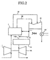
- Figure 2 is a schematic diagram of a combined electricity generation system according to a first mode of an embodiment of the present invention.
- This steam extraction pipe system 3 is provided in a condition connected between the reheating steam pipe system 31A on the low temperature side which returns the low temperature steam which drove the turbine by main steam pipe system 30 and the inlet side of pipe system 14A of the dust collecting device 14 between the outlet of the pressurized fluidized bed boiler 1 and the dust collecting device 14, and low temperature reheated steam is extracted from the reheating steam pipe system 31A, that steam is mixed with the exhaust gas of the outlet side of the pressurized fluidized bed boiler 1 and is supplied to the gas turbine 15.
- Figure 3 is a schematic diagram of a combined electricity generation system according to a second mode of the an embodiment of the present invention.
- This steam extraction pipe system 4 is arranged between the reheating steam pipe system 31A on the low temperature side and the air supply system 16A of the pressurized fluidized bed boiler 1, low temperature reheated steam is extracted, this steam is mixed into the air supply system 16A going to the pressurized fluidized bed boiler 1, and the air mixed with the steam is supplied to the pressurized fluidized bed boiler 1.
- the steam which is mixed into the air which is supplied to the pressurized fluidized bed boiler 1 is fluidized bed combusted within the pressurized fluidized bed boiler 1, flows into the dust collecting device 14 together with the exhaust gas, and is supplied to the gas turbine 15, the amount of gas which passes through the dust collecting device 14 is increased by that amount.
- the steam which has been mixed in is heated within the pressurized fluidized bed boiler 1, there is no decrease in temperature and the temperature at the gas turbine inlet does not vary from conventional systems.
- the output response of the gas turbine 15 is gradual since the mixing in is conducted indirectly via the pressurized fluidized bed boiler 1, and increases in output of the gas turbine 15 are larger than those for the above-described first mode and are the largest for the present embodiment.
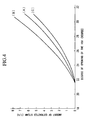
- Figure 4 shows the relationship between the degree of opening of the IGV (inlet variable guide vane) and the amount of steam extracted for each of the first and second modes of the present embodiment described above.
- the same amount of air taken in using the compressor (the temperature of the air taken in using the same compressor is determined by the degree of opening of the IGV) is shown on the horizontal axis and the necessary amount of steam extracted from each of the pipe lines which was necessary to obtain the same amount of increase in the output of the gas turbine is shown on the vertical axis, thereby, the relationship between the two is shown.
- the relationship between the amount of air taken in by the same compressor and the necessary amount of steam extracted is shown and (A) represents the background art shown in Figure 1, (B) represents the first mode shown in Figure 2, and (C) represents the second mode shown in Figure 3.
- the system for which the amount of extracted steam required for the same degree of opening of the IGV was largest was the case of the second embodiment, represented by (B), in which steam was extracted from the reheating steam pipe system 31A on the low temperature side and then mixed into the boiler output gas in the inlet side of pipe system 14A on the dust collecting device 14.
- the second largest was the case represented by (A) in which steam was extracted from the reheating steam pipe system 31 on the high temperature side and mixed into the boiler output gas in the outlet side of pipe system 15A on the dust collecting device 14.
- the case in which the amount of extracted steam required was the smallest was (C) in which the steam was extracted from the reheating steam pipe system 31A on the low temperature side and fed into the air supply system 16A of the pressurized fluidized bed boiler 1.
- the reason for the increase in output of the gas turbine 15 due to the extraction and mixing in of steam is that water (H 2 O) has a high specific heat (among the properties of the gases at the inlet to the gas turbine), and an increase in the gas flow rate is brought about by mixing steam into the gas and, as a result, this brings about the effect of increasing the output of the gas turbine 15.
- steam is mixed in to the gas and causes the moisture (H 2 O) content within the gases at the inlet of the gas turbine 15 to increase and, for the reasons mentioned above, it is possible to increase the output of the gas turbine 15.
- Figure 5 is a graph showing the amount of increase in the output of the gas turbine at partial loads which occur in the case of the second mode of (C) above.
- the amount of output increase is 100 kW or less and, when the plant load is 100%, the output increase is 150 kW or greater.
- Figure 6 is a schematic diagram of the pressurized fluidized bed combined electricity generation system according to the present embodiment.
- the pressurized fluidized bed combined electricity generation system of the present embodiment comprises a pressurized fluidized bed boiler 1, a steam extraction pipe system 2, a dust collecting device 14, a gas turbine 15, a compressor 16, a steam turbine 21, a condenser 22, a main steam pipe system 30, and a reheating steam pipe system 31.
- These structural elements have generally the same structure as the structural elements having the same references in the pressurized fluidized bed combined electricity generation systems shown in Figure 2 and Figure 9.
- the combined electricity generation system of the present embodiment is a combined electricity generation system in which air from the compressor 16 which is connected to the gas turbine 15 is supplied as fuel air for the pressurized fluidized bed boiler 1.
- the combined electricity generation system of the present embodiment has the feature of comprising a bypass pipe (a first bypass duct) 68 which is connected between the outlet side of the compressor 16 and the exhaust gas side of the above-mentioned gas turbine 15 and which has a surge prevention valve (switching valve) 67; a bypass pipe (a second bypass duct) 66 which is connected between the outlet side of the compressor 16 and the inlet side of the above-mentioned gas turbine 15 and which has a compressor outlet bypass valve (switching valve) 65; and a control device 70 which controls the above-mentioned surge prevention valve 67 and the compressor outlet bypass valve 65 (the switching valves of the first and second bypass duct) based on the relationship between the predetermined degree of opening of inlet variable guide vane 71 of the compressor and surge limiting pressures, and
- control device 70 two surge limiting pressure values which can be adjusted according to the temperature of the intake air for the compressor 16 are determined in advance.
- this control device 70 maintains the degree of opening of the inlet variable guide vane 71 and opens the surge prevention valve (the switching valve of the first bypass duct) 67. Additionally, when the other limiting pressure is reached, this control device opens the compressor outlet bypass valve (the switching valve of the second bypass passage)65.
- the combined electricity generation system of the present embodiment compresses air by means of the compressor 16 which is driven by gas turbine 15, passes it through compressor outlet valve 60, and supplies it as fuel air to the pressurized fluidized bed boiler 1 by duct 61.
- start-up gas combustor 63 is driven, air from the compressor 16 is supplied to the duct 64 side by switching the compressor outlet valve 60, and the gas turbine 15 is driven, thereby, operation is initiated.
- the air from duct 64 is shut off by switching the compressor outlet valve 60, and gas turbine 15 is driven by fuel gas from the pressurized fluidized bed boiler.
- the height of the fluidized bed is varied with respect to variation in load, the heat transfer surface area of the heat transfer pipe within the fluidized bed is increased or decreased, and the amount of steam generated is adjusted.
- the compressor outlet bypass valve 65 is provided partway along bypass pipe 66 which is arranged between the outlet side of compressor 16 and the duct 64 which is connected to the gas turbine duct on the inlet side of the gas turbine 15.
- the surge prevention valve 67 is provided partway along the bypass pipe 68 which is connected to the outlet side of the compressor 16 and the exhaust pipe duct of the gas turbine 15.
- the pressure detection device 69 measures the pressure at the outlet side of the compressor 16.
- the control device 70 receives signals for the pressure at the outlet side of the compressor 16 from the pressure detection device 69, and, as explained below, when a value just prior to the occurrence of surging of the compressor 16 is reached, the control device opens the surging prevention valve 67 or the compressor outlet bypass valve 65, and, thereby, controls in such a way as to prevent surging.
- Figure 7 is a graph showing the relationship between the compressor outlet pressure and the degree of opening of the inlet variable guide vane 71 of the compressor of the present embodiment.
- the values of the surge line (S) are known in advance for the compressor 16, and values for pressures 25% lower than the curve of this surge line (S) are the operating limit pressures and form control line (A). Furthermore, values for pressures 20% lower than the values of surge line (S) are set as control line (B).
- the value data for these control lines (A) and (B) are set in advance in control device 70 and can be controlled in such a way that adjustments are made with respect to the temperature of the intake air of the compressor 16. More specifically, in Figure 7, when the temperature of the intake air increases, the surge line (S) or the control lines (A) and (B) move downward, and when the temperature of the intake air falls, they move upward, therefore, these types of adjustments can be made by the control device 70.
- the point C is an operating point and the degree of opening of the inlet variable guide vane thereat is ⁇ 2, when the present load falls and the air flow rate of the compressor 16 falls, if the degree of opening of the inlet variable guide vane 71 is reduced; in the above-described way, since the outlet side of the compressor 16 communicates with the large pressurized container 10, shown in Figure 9, of the pressurized fluidized bed boiler 1, the pressure does not fall immediately, it is maintained in that condition, and control line (A) is reached at pressure ⁇ 1 for point C' at degree of opening ⁇ 1.
- the pressure ⁇ 1 at the outlet of the compressor for this point C' is measured by pressure detection device 69, and the degree of opening of the inlet variable guide vane 71 are maintained at ⁇ 1, the surge prevention valve 67 shown in Figure 6 is opened, and the air at the outlet side of the compressor 16 is allowed to escape from bypass pipe 68, such that the pressure at the outlet of the compressor 16 does not rise above this point.
- control device 70 as shown in Figure 8, a storage device 70A is provided, and data of control lines (A) and (B) like those shown in Figure 7 are stored in advance in this storage device 70.
- the control device 70 In the pressurized fluidized bed combined electricity generation system, when the load during operation decreases and the degree of opening of inlet variable guide vane 71 is decreased in order to reduce the amount of air in the compressor 16, the pressure at the outlet of compressor 16 during operation is measured by pressure detection device 69, and if this pressure exceeds the stipulated value of control lines (A) and (B) which are set in advance, the control device 70 immediately opens the surge prevention valve 67 or the compressor outlet bypass valve 65 in addition to maintaining the degree of opening of the inlet variable guide vane 71, and prevents a rise in the pressure by allowing an amount of air flowing to the pressurized fluidized bed boiler 1 to bypass, thereby, this control device 70 prevents surging.
- control device 70 In the following, the flow of control device 70 is explained in detail.
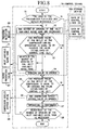
- Figure 8 is a flow chart of control within the control device 70 which carries out the control explained above.
- Step S1 when the load of the pressurized fluidized bed boiler 1 decreases, it is also necessary to decrease the amount of air from the compressor 16, therefore, as shown in Step S2, the degree of opening of the inlet variable guide vane 71 of the compressor are decreased.
- Step S3 the pressure at the outlet of the compressor is measured by the pressure detection device 69, data for the control line (A) is taken in from storage device 70A, and whether or not this measured pressure value is within the specified pressure values is checked. If the measured pressure value is equal to or exceeds the value established by control line (A), as shown in Step S4, surge prevevtion valve 67 is opened, a quantity of air is allowed to bypass, and surging is prevented. If the measured outlet pressure has not reached the pressure value established by control line (A), operations are continued without change at Step 7.
- Step S5 data of control line (B) is taken in from storage device 70, and whether or not the pressure at the outlet of the compressor 16 during operation measured by the pressure detection device 69 has reached the pressure value established by this control line (B) is checked, if it has been reached, then the compressor outlet bypass valve 65 is opened as shown in Step S6, and the air flow is again allowed to bypass, and surging is prevented. If the pressure value established by control line (B) is not reached, operation is continued without change as shown in Step S7.
- Step S7 after the processing of each of Steps S1, S3, S5, and S6, operation is continued, and as shown in Step S8, if adjustment of the degree of opening of the inlet variable guide vane is necessary, Step S2 is returned to, if this is not necessary, processing is completed.
- control device 70 reduces the degree of opening of the inlet variable guide vane in this way, the pressure at the outlet of compressor 16 does not decrease and approaches surge line (S), at the time it reaches control line (A), the degree of opening of the inlet variable guide vane 71 is maintained, surge prevention valve 67 or compressor outlet bypass valve 65 is opened, and an amount of air flowing from the outlet side of compressor 16 is allowed to bypass, and surging of compressor 16 is prevented.
Landscapes
- Engineering & Computer Science (AREA)
- Chemical & Material Sciences (AREA)
- Combustion & Propulsion (AREA)
- Mechanical Engineering (AREA)
- General Engineering & Computer Science (AREA)
- Engine Equipment That Uses Special Cycles (AREA)
- Fluidized-Bed Combustion And Resonant Combustion (AREA)
Claims (5)
- Kombiniertes Elektrizitätserzeugungssystem mit einem Druckfließbett, umfassend:dadurch gekennzeichnet, dass das kombinierte Elektrizitätserzeugungssystem mit einem Druckfließbett ferner umfasst:eine Dampfturbine (21);einen Druckfließbettboiler (1) zum Erzeugen von Dampf zur Zufuhr zu der Dampfturbine (21) über ein Hauptdampfrohrsystem (30) mittels der Verbrennung von Luft und Brennstoff;eine Gasturbine (15), die durch von dem Druckfließbettboiler (1) zugeführtes Auslaßgas und durch Luft angetrieben wird;einen Kompressor (16) zum Zuführen der Luft; undein Wiedererwärmungs-Dampfrohrsystem (31) mit einer Hochtemperaturseite und einer Niedertemperaturseite, das zwischen dem Druckfließbettboiler (1) und der Dampfturbine angeschlossen ist; undein Dampfextraktionsrohrsystem (3) zum Extrahieren eines Teils des durch den Druckfließbettboiler (1) erzeugten Dampfs,wobei die Gasturbine (15) an die Staubsammelvorrichtung (14) angeschlossen ist und durch Auslaßgas angetrieben wird, das durch die Staubsammelvorrichtung (14) hindurch zugeführt wird;eine Staubsammelvorrichtung (14), die an den Druckfließbettboiler (1) angeschlossen ist und eine Einlaßseite aufweist;
und wobei das Dampfextraktionsrohrsystem (3) einen Teil des durch den Druckbettboiler (1) erzeugten Dampfs von der Niedertemperaturseite des Wiedererwärmungs-Dampfrohrsystems (31) extrahiert und den Dampf zur Einlaßseite der Staubsammelvorrichtung (14) zuführt. - Kombiniertes Elektrizitätserzeugungssystem mit einem Druckfließbett, umfassend:dadurch gekennzeichnet, dass das kombinierte Elektrizitätserzeugungssystem mit einem Druckfließbett ferner umfasst:eine Dampfturbine (21);einen Druckfließbettboiler (1) zum Erzeugen von Dampf zur Zufuhr zu der Dampfturbine (21) über ein Hauptdampfrohrsystem (30) mittels der Verbrennung von Luft und Brennstoff;eine Gasturbine (15), die durch von dem Druckfließbettboiler (1) zugeführtes Auslaßgas und durch Luft angetrieben wird;einen Kompressor (16) mit einer Auslaßseite zum Zuführen der Luft zu dem Druckfließbettboiler (1), undein Wiedererwärmungs-Dampfrohrsystem (31) mit einer Hochtemperaturseite und einer Niedertemperaturseite, das zwischen dem Druckfließbettboiler (1) und der Dampfturbine (21) angeschlossen ist; undein Dampfextraktionsrohrsystem (4) zum Extrahieren eines Teils des durch den Druckfließbettboiler (1) erzeugten Dampfs,wobei die Gasturbine (15) an die Staubsammelvorrichtung (14) angeschlossen ist und durch Auslaßgas angetrieben wird, das durch die Staubsammelvorrichtung (14) hindurch zugeführt wird;eine Staubsammelvorrichtung (14), die an den Druckfließbettboiler (1) angeschlossen ist und eine Einlaßseite aufweist;
und wobei das Dampfextraktionsrohrsystem (4) einen Teil des durch den Druckbettboiler (1) erzeugten Dampfs von der Niedertemperaturseite des Wiedererwärmungs-Dampfrohrsystems (31) extrahiert und den Dampf zur Auslaßseite der Kompressors (16) zuführt. - Kombiniertes Elektrizitätserzeugungssystem mit einem Druckbett nach Anspruch 1 oder 2, ferner umfassend:wobei Luft von dem an die Gasturbine (15) angeschlossenen Kompressor (16) als die Luft zur Verbrennung im Druckfließbettboiler (1) zugeführt wird.eine erste Umgehungsleitung (68), die eine Verbindung zwischen einer Auslaßseite des Kompressors (16) und einer Auslaßgasseite der Gasturbine (15) herstellt, und die ein Überdruckyerhinderungsventil (67) aufweist;eine zweite Umgehungsleitung (66), die eine Verbindung zwischen der Auslaßseite des Kompressors (16) und einer Einlaßseite der Gasturbine (15) herstellt, und die ein Kompressorauslaßumgehungsventil (65) aufweist; undeine Steuer-/Regelvorrichtung (70), die gemessene Druckwerte von einer Druckerfassungsvorrichtung empfängt, welche den Druck an der Auslaßseite des Kompressors (16) erfasst, und die Ventile der ersten und der zweiten Umgehungsleitungen (68, 66) basierend auf einem Zusammenhang zwischen einem Überdruckbegrenzungsdruck und einem vorbestimmten Öffnungsgrad einer Einlaß-verstellbaren Leitschaufel (71) des Kompressors (16) steuert/regelt;
- Kombiniertes Elektrizitätserzeugungssystem mit einem Druckfließbett nach Anspruch 3, wobei:die Steuer-/Regelvorrichtung (70) dazu ausgelegt ist, vorher zwei Überdruckbegrenzungsdruckwerte zu ermitteln und den vorbestimmten Öffnungsgrad der Einlaß-variablen Leitschaufel (71) beizubehalten und das Überdruckverhinderungsventil (67) der ersten Umgehungsleitung (68) zu öffnen, wenn der Druckdetektor erfasst, dass ein Druck während des Betriebs einen Druck gemäß einem der Überdruckbegrenzungsdruckwerte erreicht, und wobei die Steuer-/Regelvorrichtung (70) dazu ausgelegt ist, das Auslaßumgehungsventil der zweiten Umgehungsleitung (66) zu öffnen, wenn der Druckdetektor erfasst, dass der Druck während des Betriebs den anderen Überdruckbegrenzungsdruckwert erreicht.
- Kombiniertes Elektrizitätserzeugungssystem mit einem Druckfließbett nach Anspruch 4, wobei die Steuer-/Regelvorrichtung (70) dazu ausgelegt ist, die vorher ermittelten Werte der zwei Überdruckbegrenzungsdrücke abhängig von einer Temperatur der Einlaßluft des Kompressors (16) anzupassen.
Applications Claiming Priority (3)
| Application Number | Priority Date | Filing Date | Title |
|---|---|---|---|
| JP17191797A JP3621809B2 (ja) | 1997-06-27 | 1997-06-27 | 複合発電システムにおけるガスタービン出力増加方法 |
| JP17191797 | 1997-06-27 | ||
| PCT/JP1998/002899 WO1999000586A1 (en) | 1997-06-27 | 1998-06-29 | Pressurized fluidized-bed combined cycle power generation system |
Publications (3)
| Publication Number | Publication Date |
|---|---|
| EP0933504A1 EP0933504A1 (de) | 1999-08-04 |
| EP0933504A4 EP0933504A4 (de) | 2002-07-10 |
| EP0933504B1 true EP0933504B1 (de) | 2005-03-16 |
Family
ID=15932247
Family Applications (1)
| Application Number | Title | Priority Date | Filing Date |
|---|---|---|---|
| EP98929732A Expired - Lifetime EP0933504B1 (de) | 1997-06-27 | 1998-06-29 | Kombiniertes kraftwerk mit einer druckwirbelschicht |
Country Status (5)
| Country | Link |
|---|---|
| US (1) | US6212872B1 (de) |
| EP (1) | EP0933504B1 (de) |
| JP (1) | JP3621809B2 (de) |
| DE (1) | DE69829354D1 (de) |
| WO (1) | WO1999000586A1 (de) |
Cited By (1)
| Publication number | Priority date | Publication date | Assignee | Title |
|---|---|---|---|---|
| WO2014187224A1 (zh) * | 2013-05-21 | 2014-11-27 | 国家电网公司 | 一种电厂增压风机辅机故障减负荷rb的方法及装置 |
Families Citing this family (10)
| Publication number | Priority date | Publication date | Assignee | Title |
|---|---|---|---|---|
| US6526758B2 (en) * | 2000-05-12 | 2003-03-04 | General Electric Company | Method and apparatus for power augmentation for gas turbine power cycles |
| US6968700B2 (en) | 2001-03-01 | 2005-11-29 | Lott Henry A | Power systems |
| US6467273B1 (en) | 2001-03-01 | 2002-10-22 | Henry A. Lott | Method for producing electrical power |
| US6841683B2 (en) * | 2001-08-30 | 2005-01-11 | Teva Pharmaceutical Industries Ltd. | Sulfonation method for zonisamide intermediate in zonisamide synthesis and their novel crystal forms |
| US7896956B2 (en) * | 2006-11-30 | 2011-03-01 | Mitsubishi Heavy Industries, Ltd. | Method for regenerating filter and apparatus thereof |
| US20110005747A1 (en) * | 2009-07-10 | 2011-01-13 | Loebig James C | Method and system for enhanced oil recovery |
| JP5832944B2 (ja) * | 2012-03-26 | 2015-12-16 | 月島機械株式会社 | 加圧流動炉システムの非常停止方法 |
| CN111035263A (zh) * | 2019-12-31 | 2020-04-21 | 深圳酷平方科技有限公司 | 一种烹饪进程中的烹饪器具的内表面温度的计算方法 |
| CN113202581B (zh) * | 2021-05-07 | 2024-09-03 | 中国大唐集团科学技术研究院有限公司华东电力试验研究院 | 一种燃机冷却系统以及冷却方法 |
| CN114076004B (zh) * | 2021-11-02 | 2023-08-25 | 国能寿光发电有限责任公司 | 一种中压供热系统及中压供热方法 |
Family Cites Families (8)
| Publication number | Priority date | Publication date | Assignee | Title |
|---|---|---|---|---|
| US3795816A (en) * | 1972-05-09 | 1974-03-05 | Sulzer Ag | Apparatus to prevent overspeeding of a combination including a supercharged steam generator, a gas turbine and a compressor |
| JPH01116205A (ja) * | 1987-10-30 | 1989-05-09 | Hitachi Ltd | 複合発電設備の出力制御装置 |
| JP2908884B2 (ja) * | 1991-01-31 | 1999-06-21 | 株式会社日立製作所 | 加圧流動床コンバインドプラントとその部分負荷運転制御方法及びその制御装置 |
| US5375409A (en) * | 1993-10-08 | 1994-12-27 | Ahlstrom Pyropower, Inc. | Pressurized fluidized bed combined gas turbine and steam turbine power plant with steam injection |
| JPH08166109A (ja) * | 1994-12-14 | 1996-06-25 | Mitsubishi Heavy Ind Ltd | 加圧流動床プラント |
| SE9502234L (sv) * | 1995-06-20 | 1996-09-30 | Abb Carbon Ab | Förfarande samt anordning för tilläggsenergialstring i en kraftanläggning |
| JP3145617B2 (ja) * | 1995-08-30 | 2001-03-12 | 三菱重工業株式会社 | 加圧流動床複合発電プラントの圧縮機制御装置 |
| US5918466A (en) * | 1997-02-27 | 1999-07-06 | Siemens Westinghouse Power Corporation | Coal fuel gas turbine system |
-
1997
- 1997-06-27 JP JP17191797A patent/JP3621809B2/ja not_active Expired - Fee Related
-
1998
- 1998-06-29 EP EP98929732A patent/EP0933504B1/de not_active Expired - Lifetime
- 1998-06-29 WO PCT/JP1998/002899 patent/WO1999000586A1/ja not_active Ceased
- 1998-06-29 US US09/147,734 patent/US6212872B1/en not_active Expired - Fee Related
- 1998-06-29 DE DE69829354T patent/DE69829354D1/de not_active Expired - Lifetime
Cited By (1)
| Publication number | Priority date | Publication date | Assignee | Title |
|---|---|---|---|---|
| WO2014187224A1 (zh) * | 2013-05-21 | 2014-11-27 | 国家电网公司 | 一种电厂增压风机辅机故障减负荷rb的方法及装置 |
Also Published As
| Publication number | Publication date |
|---|---|
| JPH1113417A (ja) | 1999-01-19 |
| EP0933504A4 (de) | 2002-07-10 |
| EP0933504A1 (de) | 1999-08-04 |
| US6212872B1 (en) | 2001-04-10 |
| WO1999000586A1 (en) | 1999-01-07 |
| DE69829354D1 (de) | 2005-04-21 |
| JP3621809B2 (ja) | 2005-02-16 |
Similar Documents
| Publication | Publication Date | Title |
|---|---|---|
| US5203159A (en) | Pressurized fluidized bed combustion combined cycle power plant and method of operating the same | |
| US8408007B2 (en) | Integrated gasification combined cycle and operation control method thereof | |
| JP4939511B2 (ja) | 石炭ガス化複合発電設備 | |
| JP5482792B2 (ja) | 有機性廃棄物処理システム及び方法 | |
| US6212872B1 (en) | Pressurized fluidized-bed combined cycle power generation system | |
| EP0915242B1 (de) | Gasturbine | |
| US20070193249A1 (en) | Air pressure control device in integrated gasification combined cycle system | |
| JP3140793B2 (ja) | セラミック製フィルタの入口温度の制御 | |
| JPH11210495A (ja) | ガスタービン | |
| US5375409A (en) | Pressurized fluidized bed combined gas turbine and steam turbine power plant with steam injection | |
| US6293087B2 (en) | Pressurized fluidized bed combined electricity generation system | |
| JP2002327915A (ja) | 微粉炭焚ボイラ設備のミル一次空気流量制御装置 | |
| JP3530344B2 (ja) | 加圧流動層複合発電システムの圧縮機サージング防止装置 | |
| CA2264115C (en) | Pressurized fluidized-bed combined cycle power generation system | |
| GB2148734A (en) | Divided fluidised bed | |
| JP2000266310A (ja) | 加圧流動層ボイラ装置およびその制御方法 | |
| JPH0996227A (ja) | ガス化プラントの圧力制御装置 | |
| JP3845905B2 (ja) | 排気再燃型コンバインドサイクルプラントにおけるガス高圧給水加熱器の出口給水温度制御装置 | |
| KR100896628B1 (ko) | 보일러 화로압력 선행 직접제어 시스템 | |
| JP7246293B2 (ja) | 廃棄物処理設備及びその運転方法 | |
| JPH1114003A (ja) | 加圧流動層ボイラの蒸気温度制御装置 | |
| JPH02233807A (ja) | 石炭ガス化発電プラント制御装置 | |
| JPS61145322A (ja) | 石炭ガス化コンバインドサイクルプラントの制御装置 | |
| JPH07260122A (ja) | 流動床炉における安定燃焼方法及び装置 | |
| JPH05296407A (ja) | 排気再燃形コンバインドサイクル発電設備 |
Legal Events
| Date | Code | Title | Description |
|---|---|---|---|
| PUAI | Public reference made under article 153(3) epc to a published international application that has entered the european phase |
Free format text: ORIGINAL CODE: 0009012 |
|
| 17P | Request for examination filed |
Effective date: 19990302 |
|
| AK | Designated contracting states |
Kind code of ref document: A1 Designated state(s): CH DE FR GB IT LI |
|
| A4 | Supplementary search report drawn up and despatched |
Effective date: 20020524 |
|
| AK | Designated contracting states |
Kind code of ref document: A4 Designated state(s): CH DE FR GB IT LI |
|
| 17Q | First examination report despatched |
Effective date: 20030120 |
|
| GRAP | Despatch of communication of intention to grant a patent |
Free format text: ORIGINAL CODE: EPIDOSNIGR1 |
|
| GRAS | Grant fee paid |
Free format text: ORIGINAL CODE: EPIDOSNIGR3 |
|
| GRAA | (expected) grant |
Free format text: ORIGINAL CODE: 0009210 |
|
| AK | Designated contracting states |
Kind code of ref document: B1 Designated state(s): CH DE FR GB IT LI |
|
| PG25 | Lapsed in a contracting state [announced via postgrant information from national office to epo] |
Ref country code: IT Free format text: LAPSE BECAUSE OF FAILURE TO SUBMIT A TRANSLATION OF THE DESCRIPTION OR TO PAY THE FEE WITHIN THE PRESCRIBED TIME-LIMIT;WARNING: LAPSES OF ITALIAN PATENTS WITH EFFECTIVE DATE BEFORE 2007 MAY HAVE OCCURRED AT ANY TIME BEFORE 2007. THE CORRECT EFFECTIVE DATE MAY BE DIFFERENT FROM THE ONE RECORDED. Effective date: 20050316 |
|
| REG | Reference to a national code |
Ref country code: GB Ref legal event code: FG4D |
|
| REG | Reference to a national code |
Ref country code: CH Ref legal event code: EP |
|
| REF | Corresponds to: |
Ref document number: 69829354 Country of ref document: DE Date of ref document: 20050421 Kind code of ref document: P |
|
| REG | Reference to a national code |
Ref country code: CH Ref legal event code: NV Representative=s name: BOVARD AG PATENTANWAELTE |
|
| PG25 | Lapsed in a contracting state [announced via postgrant information from national office to epo] |
Ref country code: DE Free format text: LAPSE BECAUSE OF FAILURE TO SUBMIT A TRANSLATION OF THE DESCRIPTION OR TO PAY THE FEE WITHIN THE PRESCRIBED TIME-LIMIT Effective date: 20050617 |
|
| PGFP | Annual fee paid to national office [announced via postgrant information from national office to epo] |
Ref country code: FR Payment date: 20050624 Year of fee payment: 8 |
|
| PGFP | Annual fee paid to national office [announced via postgrant information from national office to epo] |
Ref country code: CH Payment date: 20050628 Year of fee payment: 8 |
|
| PG25 | Lapsed in a contracting state [announced via postgrant information from national office to epo] |
Ref country code: GB Free format text: LAPSE BECAUSE OF NON-PAYMENT OF DUE FEES Effective date: 20050629 |
|
| PLBE | No opposition filed within time limit |
Free format text: ORIGINAL CODE: 0009261 |
|
| STAA | Information on the status of an ep patent application or granted ep patent |
Free format text: STATUS: NO OPPOSITION FILED WITHIN TIME LIMIT |
|
| ET | Fr: translation filed | ||
| GBPC | Gb: european patent ceased through non-payment of renewal fee |
Effective date: 20050629 |
|
| 26N | No opposition filed |
Effective date: 20051219 |
|
| PG25 | Lapsed in a contracting state [announced via postgrant information from national office to epo] |
Ref country code: LI Free format text: LAPSE BECAUSE OF NON-PAYMENT OF DUE FEES Effective date: 20060630 Ref country code: CH Free format text: LAPSE BECAUSE OF NON-PAYMENT OF DUE FEES Effective date: 20060630 |
|
| REG | Reference to a national code |
Ref country code: CH Ref legal event code: PL |
|
| REG | Reference to a national code |
Ref country code: FR Ref legal event code: ST Effective date: 20070228 |
|
| PG25 | Lapsed in a contracting state [announced via postgrant information from national office to epo] |
Ref country code: FR Free format text: LAPSE BECAUSE OF NON-PAYMENT OF DUE FEES Effective date: 20060630 |