EP0933505A2 - Système refroidi par vapeur dans une centrale à cycle combiné - Google Patents
Système refroidi par vapeur dans une centrale à cycle combiné Download PDFInfo
- Publication number
- EP0933505A2 EP0933505A2 EP99101211A EP99101211A EP0933505A2 EP 0933505 A2 EP0933505 A2 EP 0933505A2 EP 99101211 A EP99101211 A EP 99101211A EP 99101211 A EP99101211 A EP 99101211A EP 0933505 A2 EP0933505 A2 EP 0933505A2
- Authority
- EP
- European Patent Office
- Prior art keywords
- steam
- temperature
- cooling
- gas turbine
- pressure
- Prior art date
- Legal status (The legal status is an assumption and is not a legal conclusion. Google has not performed a legal analysis and makes no representation as to the accuracy of the status listed.)
- Granted
Links
- 238000001816 cooling Methods 0.000 claims abstract description 116
- 239000007789 gas Substances 0.000 claims abstract description 99
- 238000011084 recovery Methods 0.000 claims abstract description 26
- 239000002918 waste heat Substances 0.000 claims abstract description 15
- 239000000446 fuel Substances 0.000 claims description 34
- 238000012544 monitoring process Methods 0.000 claims description 10
- 238000010276 construction Methods 0.000 description 11
- 230000000694 effects Effects 0.000 description 3
- 230000010354 integration Effects 0.000 description 3
- 230000008646 thermal stress Effects 0.000 description 3
- 238000002485 combustion reaction Methods 0.000 description 2
- 230000003247 decreasing effect Effects 0.000 description 2
- 238000010438 heat treatment Methods 0.000 description 2
- 230000001133 acceleration Effects 0.000 description 1
- 239000000567 combustion gas Substances 0.000 description 1
- 239000002826 coolant Substances 0.000 description 1
- 230000002708 enhancing effect Effects 0.000 description 1
- 230000002349 favourable effect Effects 0.000 description 1
- 238000000034 method Methods 0.000 description 1
- 230000000630 rising effect Effects 0.000 description 1
Images
Classifications
-
- F—MECHANICAL ENGINEERING; LIGHTING; HEATING; WEAPONS; BLASTING
- F01—MACHINES OR ENGINES IN GENERAL; ENGINE PLANTS IN GENERAL; STEAM ENGINES
- F01K—STEAM ENGINE PLANTS; STEAM ACCUMULATORS; ENGINE PLANTS NOT OTHERWISE PROVIDED FOR; ENGINES USING SPECIAL WORKING FLUIDS OR CYCLES
- F01K23/00—Plants characterised by more than one engine delivering power external to the plant, the engines being driven by different fluids
- F01K23/02—Plants characterised by more than one engine delivering power external to the plant, the engines being driven by different fluids the engine cycles being thermally coupled
- F01K23/06—Plants characterised by more than one engine delivering power external to the plant, the engines being driven by different fluids the engine cycles being thermally coupled combustion heat from one cycle heating the fluid in another cycle
- F01K23/10—Plants characterised by more than one engine delivering power external to the plant, the engines being driven by different fluids the engine cycles being thermally coupled combustion heat from one cycle heating the fluid in another cycle with exhaust fluid of one cycle heating the fluid in another cycle
- F01K23/106—Plants characterised by more than one engine delivering power external to the plant, the engines being driven by different fluids the engine cycles being thermally coupled combustion heat from one cycle heating the fluid in another cycle with exhaust fluid of one cycle heating the fluid in another cycle with water evaporated or preheated at different pressures in exhaust boiler
- F01K23/108—Regulating means specially adapted therefor
-
- Y—GENERAL TAGGING OF NEW TECHNOLOGICAL DEVELOPMENTS; GENERAL TAGGING OF CROSS-SECTIONAL TECHNOLOGIES SPANNING OVER SEVERAL SECTIONS OF THE IPC; TECHNICAL SUBJECTS COVERED BY FORMER USPC CROSS-REFERENCE ART COLLECTIONS [XRACs] AND DIGESTS
- Y02—TECHNOLOGIES OR APPLICATIONS FOR MITIGATION OR ADAPTATION AGAINST CLIMATE CHANGE
- Y02E—REDUCTION OF GREENHOUSE GAS [GHG] EMISSIONS, RELATED TO ENERGY GENERATION, TRANSMISSION OR DISTRIBUTION
- Y02E20/00—Combustion technologies with mitigation potential
- Y02E20/16—Combined cycle power plant [CCPP], or combined cycle gas turbine [CCGT]
-
- Y—GENERAL TAGGING OF NEW TECHNOLOGICAL DEVELOPMENTS; GENERAL TAGGING OF CROSS-SECTIONAL TECHNOLOGIES SPANNING OVER SEVERAL SECTIONS OF THE IPC; TECHNICAL SUBJECTS COVERED BY FORMER USPC CROSS-REFERENCE ART COLLECTIONS [XRACs] AND DIGESTS
- Y02—TECHNOLOGIES OR APPLICATIONS FOR MITIGATION OR ADAPTATION AGAINST CLIMATE CHANGE
- Y02P—CLIMATE CHANGE MITIGATION TECHNOLOGIES IN THE PRODUCTION OR PROCESSING OF GOODS
- Y02P80/00—Climate change mitigation technologies for sector-wide applications
- Y02P80/10—Efficient use of energy, e.g. using compressed air or pressurized fluid as energy carrier
- Y02P80/15—On-site combined power, heat or cool generation or distribution, e.g. combined heat and power [CHP] supply
Definitions
- the present invention relates generally to a steam cooled system in a combined cycle power plant and more specifically to that constructed such that a high temperature portion (portion to be cooled) of gas turbine combustor etc. in a combined cycle power plant in which a gas turbine plant and a steam turbine plant are combined together is cooled by steam coming from a waste heat recovery boiler.
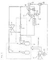
- Fig. 3 shows a prior art gas turbine steam system in a combined cycle power plant.
- numeral 1 designates a gas turbine
- numeral 2 designates a waste heat recovery boiler thereof
- numeral 3 designates a high pressure steam turbine
- numeral 4 designates an intermediate pressure steam turbine.
- the waste heat recovery boiler 2 comprises a high pressure drum 5, a high pressure superheater 6, a reheater 7, an intermediate pressure drum 9, an intermediate pressure superheater 10, etc.
- Numeral 8 designates a high temperature portion (or a heat exchanger therefor) of gas turbine combustor etc., which is a portion to be cooled by steam.
- Numeral 12 designates a temperature control valve, which is controlled by a temperature control device 11.
- Numeral 13 designates a superheater outlet steam temperature detector and numeral 15 designates a high temperature portion outlet steam temperature detector.
- exhaust gas of the gas turbine 1 is led into the waste heat recovery boiler 2.
- Steam from the high pressure drum 5 of the waste heat recovery boiler 2 is led into the high pressure steam turbine 3 via the high pressure superheater 6.
- steam from the intermediate pressure drum 9 is led into the intermediate pressure steam turbine 4 via the intermediate pressure superheater 10 and the reheater 7 sequentially.
- Outlet steam of the high pressure steam turbine 3 joins in an inlet steam of the reheater 7.
- outlet steam of the intermediate pressure superheater 10 diverges partly from that led to the reheater 7 to flow through the temperature control valve 12 and the high temperature portion 8 of the gas turbine combustor etc. Sequentially and then joins in the outlet steam of the reheater 7 to be led into the intermediate pressure steam turbine 4.
- Output of the high temperature portion outlet steam temperature detector 15 which is provided at an outlet of the high temperature portion 8 is sent to the temperature control valve 12 which is provided in a steam line on an inlet side of the high temperature portion 8 via the temperature control device 11.
- the exhaust gas of the gas turbine 1 enters the waste heat recovery boiler 2 to generate a high pressure steam, an intermediate pressure steam and a low pressure steam.
- the steam generated at the high pressure drum 5 becomes a superheated steam at the high pressure superheater 6 to work at the high pressure steam turbine 3 and flows through a high pressure exhaust steam line to join in the intermediate pressure steam and then is reheated at the reheater 7 to be led into the intermediate pressure steam turbine 4.
- Steam generated at the intermediate pressure drum 9 is superheated at the intermediate pressure superheater 10 and is led in a necessary amount to the high temperature portion 8 of the gas turbine 1 combustor etc. for cooling thereof either through a heat exchanger or directly in the high temperature portion 8 and then joins in the outlet steam of the reheater 7.
- Surplus steam joins in the steam coming from the high pressure steam turbine 3 through the high pressure exhaust steam line to be led to the reheater 7.
- temperature thereof is controlled such that the temperature control valve 12, which is provided in the steam line on the inlet side of the high temperature portion 8, is controlled by a control signal from the high temperature portion outlet steam temperature detector 15 and the temperature control device 11 so that flow rate of the steam is controlled.
- Said prior art steam cooled system is a system in which the steam used for cooling of the high temperature portion 8 of the gas turbine combustor etc. is controlled of its flow rate by the temperature control valve 12 provided at an inlet of the high temperature portion 8 so that the outlet steam temperature of the high temperature portion 8 is set to a predetermined value.
- the high temperature portion such as combustor etc.
- the present invention provides a steam cooled system in a combined cycle power plant constructed such that there is provided a temperature control valve at a cooling steam outlet of a high temperature portion of gas turbine and said temperature control valve performs a cooling steam temperature control so that temperature of cooling steam coming out of said high temperature portion is set to a predetermined value as well as performs a cooling steam pressure control, which is preferential to said cooling steam temperature control, so that pressure of the cooling steam coming out of said high temperature portion may not become lower than pressure in a turbine cylinder of said gas turbine.
- the cooling steam pressure control is preferential to the cooling steam temperature control and there occurs no case that the temperature control valve provided at the cooling steam outlet of the high temperature portion opens beyond the opening at that time, hence the cooling steam pressure by no means lowers further and is maintained higher than the pressure in the gas turbine cylinder (discharge pressure of gas turbine air compressor).
- Said steam cooled system may be constructed such that there are provided a cooling steam temperature control system for controlling said temperature control valve so that a cooling steam temperature at said cooling steam outlet is set to a predetermined value and a cooling steam pressure control system for controlling said temperature control valve so that a cooling steam pressure at said cooling steam outlet may not become lower than pressure in a turbine cylinder of said gas turbine and said temperature control valve is operated by a lower value out of control signals of said temperature control system and said pressure control system.
- the cooling steam pressure is maintained higher than the pressure in the gas turbine cylinder (discharge pressure of gas turbine air compressor) and the high temperature portion can be cooled within the range of the cooling steam pressure not becoming lower than the pressure in the gas turbine cylinder.
- the present invention provides a steam cooled system in a combined cycle power plant constructed such that there is provided a control device for controlling a flow rate of cooling steam supplied into said steam cooled system, based on an outlet steam temperature of said steam cooled system and a fuel supply rate to said gas turbine.
- the fuel supply rate of the fuel supplied into the gas turbine is made one control factor and in addition thereto, the outlet steam temperature of the steam cooled system is made another control factor, thus the steam flow rate of the cooling steam supplied into the steam cooled system is controlled appropriately.
- occurrence of disorder such as occurrence of cracks, clogging of steam system or the like, in the gas turbine high temperature portion is detected earlier by use of a temperature detecting signal of a high temperature portion outlet steam temperature detector so that a safe operation of the gas turbine may be effected.
- the present invention provides an outlet steam monitoring system in a steam cooled type gas turbine, said steam cooled type gas turbine being constructed such that a cooling steam is supplied into a high temperature portion of combustor, blade or the like and the cooling steam after used for cooling is recovered, characterized in that there are provided a temperature detector for detecting an outlet temperature of said steam after used for cooling and a control device which, being inputted a detected signal of said temperature detector for comparison with a predetermined temperature value, puts out a warning signal as well as a signal for throttling opening of a fuel flow control valve to a predetermined opening or a signal for closing a shut-off valve, if a detected temperature of said temperature detector exceeds said predetermined temperature value.
- the outlet steam temperature of the steam which has cooled the high temperature portion is detected by the temperature detector and this detected signal is inputted into the control device.
- the outlet steam temperature at the normal state, the temperature at the dangerous state, the upper limit temperature to shut off the fuel, etc. are set in advance and the detected temperature is compared therewith. If the detected temperature exceeds the set temperature, the warning signal, the signal for throttling the opening of the flow control valve and the signal for closing the shut-off valve are put out corresponding to the respective level of the temperature rise. Thereby, disorder in the high temperature portion is detected earlier and a dangerous state can be avoided by said signals of the control device.
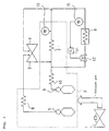
- a temperature control valve 12 is provided on an outlet side of cooling steam of a high temperature portion 8, such as combustor etc.
- Numeral 16 designates a high temperature portion outlet steam pressure detector and numeral 17 designates a gas turbine cylinder pressure detector. Construction thereof is made such that signals from these pressure detectors 16, 17 are given to a subtractor 20.
- Numeral 18 designates a pressure controller, which receives output signal from the subtractor 20.
- Numeral 19 designates a lower value selector, which receives signals from a temperature controller 11 and the pressure controller 18 to select a lower value thereof.
- Other portions of the construction thereof are substantially same as those of the gas turbine steam cooled system shown in Fig. 3 and description thereon will be omitted.
- a signal showing a cooling steam temperature detected at a high temperature portion outlet steam temperature detector 15 is sent to the temperature controller 11 and the temperature control valve 12 is adjusted so as to set a high temperature portion outlet steam temperature to a predetermined set value.
- the temperature controller 11 generates a signal such that, if the cooling steam temperature at an outlet of the high temperature portion 8 is higher than the set value, the temperature control valve 12 is operated in the direction to open to increase flow rate of the cooling steam or reversely if the cooling steam temperature at the outlet of the high temperature portion 8 is lower than the set value, the temperature control valve 12 is operated in the direction to close to decrease the flow rate of the cooling steam.
- a cooling steam pressure at the outlet of the high temperature portion 8 is detected by the pressure detector 16 and pressure in a gas turbine cylinder (discharge pressure of gas turbine air compressor) is detected by the pressure detector 17, respectively, and respective signals showing such measured pressures are inputted into the subtractor 20 to be subtracted therein. If there is recognized a tendency that the cooling steam pressure becomes lower than the pressure in the turbine cylinder, the pressure controller 18 generates a signal such that the temperature control valve 12 is operated in the direction to close.
- the respective signals sent from the temperature controller 11 and the pressure controller 18 are inputted into the lower value selector 19 to be compared of their sizes and the lower value is selected to be put out as a signal to operate the temperature control valve 12.
- the temperature controller 11 can do control such that a rise of the cooling steam temperature at the outlet of the high temperature portion 8 is suppressed as much as possible within the range of the outlet steam pressure of the high temperature portion 8 not becoming lower than the pressure in the gas turbine cylinder.
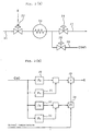
- FIG. 2 only a construction around the gas turbine high temperature portion to be cooled by steam is shown and other portions of the construction of the combined cycle power plant being substantially same as those shown in Fig. 1, description thereon will be omitted.
- Fig 2(a) shows a portional equipment arrangement in a main part of a cooling steam flow.
- Numeral 21 designates a cooling steam supply passage, which supplies therethrough a high pressure turbine exhaust steam or a generated steam of a waste heat recovery boiler etc. (not shown) as a cooling steam.
- Numeral 22 designates a temperature control valve provided in the cooling steam supply passage 21, which is controlled to be opened and closed by an opening and closing command E obtained in a control circuit as described later.
- Numeral 23 designates a combustor disposed subsequently to the temperature control valve 22
- numeral 24 designates a pressure control valve provided in a cooling steam recovery passage 27
- numeral 25 designates a pressure control valve provided in a condenser connection passage 26 which connects to a condenser (not shown).
- Fig. 2(b) shows a control circuit for generating said opening and closing command E, wherein an input command on one hand is a fuel control signal CSO (Control signal output) for controlling flow rate of fuel supplied into the combustor 23 and this fuel control signal CSO is first computed by function units 30, 31, 32 and 33, respectively.
- CSO Control signal output
- an input command on the other hand is an outlet steam temperature (actual temperature) of the combustor 23 and computation is done at a computing unit 34 which performs a proportional integration together with signals based on outputs of the function units 32, 33 and result thereof is added at an adder 35 to signals based on outputs of the function units 30, 31 so that said opening and closing command E is generated.
- a computing unit 34 which performs a proportional integration together with signals based on outputs of the function units 32, 33 and result thereof is added at an adder 35 to signals based on outputs of the function units 30, 31 so that said opening and closing command E is generated.
- the fuel control signal CSO is corrected corresponding to a temperature of air charged for combustion etc. and an opening command value and a temperature set value of the temperature control valve 22 are decided based thereon so that a sudden change in the fuel control signal CSO may be followed up well.
- the opening command value and the temperature set value, respectively, may be changed instantly by a fuel change-over command so that a change of the fuel may be followed up quickly.
- the temperature set value is computed in comparison with the actual temperature by a proportional integration computation (PI control) or by a proportional computation (P control) and result thereof is added to the opening command value, wherein there is set an upper limit in a direction of throttling and if the opening command is in saturation (100% or more), output of the proportional integration computation (PI) or the like is fixed to that value.
- PI control proportional integration computation
- P control proportional computation
- the cooling steam flow rate is controlled advance-wise based on a certain function setting corresponding to the fuel supply rate into the gas turbine.
- the cooling steam flow rate is controlled relying only on the temperature of the cooling steam which has been used for cooling of the high temperature portion, there is a fear of delay due to thermal capacity of pipings etc. downstream of the high temperature portion, there is no such a fear in the present embodiment and unusual excess cooling or heating can be prevented and a favorable cooling by steam, which suppresses occurrence of thermal stresses at the high temperature portion to be cooled, can be realized.
- FIG. 3 An example as embodiment 3 where a monitoring system is constructed for monitoring an outlet steam temperature of a steam cooled type gas turbine using a temperature detecting signal of a combustor etc. high temperature portion outlet steam temperature detector will be described with reference to Figs. 4 and 5.
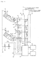
- numeral 41 designates a steam supply manifold and numeral 42 designates a flow control valve, which controls flow rate of steam to be supplied.
- Numeral 43 designates a supply line, which supplies therethrough a cooling steam into a cooling steam supply pipe 65 of each of a plurality of combustor main bodies 60 from the steam supply manifold 41.
- Numeral 44 designates a recovery line, numeral 45 designates a steam recovery manifold and steam recovered through the recovery line 44 from cooling steam recovery pipes 66, 67 of each of the plurality of combustor main bodies 60 is recovered into the steam recovery manifold 45.
- Numeral 46 designates a temperature detector, which detects temperature of inlet steam flowing through the supply line 43 connecting to each of the plurality of combustor main bodies 60 to send a signal thereof to a control device 50 via an inlet steam temperature detecting line 47.
- Numeral 48 also designates a temperature detector, which detects temperature of the steam recovered flowing through the recovery line 44 from the cooling steam recovery pipes 66, 67 to send a signal thereof to the control device 50 via an outlet steam temperature detecting line 49.
- Numeral 50 designates the control device mentioned above
- numeral 51 designates a display for displaying result of computation at the control device 50
- numeral 52 designates a warning device for giving a warning by an alarm etc. when something wrong is found as the result of computation at the control device 50
- Numeral 53 designates a control signal line, wherein a line 53a thereof transmits therethrough a signal to control opening of a flow control valve 55 of a fuel system 54 and a line 53b thereof transmits therethrough a signal to control opening and closing of a shut-off valve 56.
- an inlet steam temperature detected by the temperature detector 46 of each of the combustors as the high temperature portions and an outlet steam temperature detected by the temperature detector 48 of the steam recovered from the cooling steam recovery pipes 66, 67 of each of the combustors are inputted into the control device 50.
- Temperature of the steam supplied is approximately a planned supply steam temperature and temperature of the steam recovered is approximately a planned outlet steam temperature at a normal operation time.
- the control device 50 confirms whether the inlet steam temperature is normal as being approximately the planned supply steam temperature or not and then monitors the outlet steam temperature. While the outlet steam temperature is approximately the planned outlet steam temperature at the normal operation time, if there occurs an unusual case, such as clogging of steam passage, occurrence of cracks or the like, in the combustor main body, the temperature rises to a dangerous level or more to cause a dangerous situation, hence the control is done such that the situation of temperature is displayed on the display 51 as well as the signal thereof is sent to the warning device 52 so as to generate a warning.
- control device 50 sends a control signal through the control signal line 53b to throttle opening of the flow control valve 55 so that the fuel in the fuel system is decreased to control the load, and if the temperature rises further to become higher than an upper limit temperature, for example a shut-off temperature, a control signal is put out through the control signal line 53a to control the shut-off valve 56 to be closed and the gas turbine is tripped.
- an upper limit temperature for example a shut-off temperature
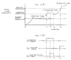
- Fig. 5 is an explanatory view of the situation mentioned above, wherein Fig. 5(a) shows changes in the outlet steam temperature and Fig. 5(b) shows control signals corresponding to the temperature.
- the outlet steam temperature is in the state of approximately the planned outlet steam temperature at the normal operation time as shown by (X), and if the temperature rises beyond the dangerous temperature at time t 1 as shown by (Y,), the control device 50 recognizes a dangerous situation of the combustor main body 60 to put out a warning signal (S 1 ) as shown in Fig. 5(b) continuously during the time t 1 to t 2 exceeding the dangerous temperature and the warning device 51 is operated.
- S 1 warning signal
- the control device puts out a load decreasing signal (S 3 ) as shown in Fig. 5(b) to control opening of the flow control valve 55 of the fuel system 54 to be throttled. If the temperature rises further to exceed the shut-off temperature at time t 3 as shown by (Y 2 ), a shut-off signal (S 2 ) as shown in Fig. 5(b) is put out to close the shut-off valve 56 of the fuel system 54 so that fuel supply to a main fuel supply pipe 63 is stopped and the gas turbine is tripped.
- S 3 load decreasing signal
- Fig. 4 is made in a form of omission on the example where the plurality of the combustor main bodies 60 are arranged in the common fuel system 54 to control the flow control valve 55 and the shut-off valve 56 commonly, needless to mention, it is necessary to control the flow control valve and the shut-off valve of the respective fuel system independently with respect to each of the combustor main bodies 60, wherein accident or disorder of each of the combustors is detected, flow rate of only the combustor on which disorder has been detected is controlled and the shut-off valve thereof is closed.
- the invention is not limited thereto but may be applied to a temperature monitoring of an object to be cooled not only of the combustor but also of a stationary blade and a moving blade with same function and effect.
- temperature of the outlet steam recovered through the recovery line 44 from the cooling steam recovery pipes 66, 67 of the combustor main body 60 is detected by the temperature detector 48 to be inputted into the control device 50 so that the temperature rise is monitored by the control device 50 and if the outlet steam temperature exceeds the predetermined temperature, the warning device 52 is operated to generate a warning as well as the flow control valve 55 is controlled to control the fuel flow rate or to close the shut-off valve 56 to stop the fuel supply, thereby disorder of the combustor can be detected earlier by the change in the outlet steam temperature and a safe operation of the gas turbine can be ensured.
- the construction is made such that there is provided the temperature control valve at the cooling steam outlet of the high temperature portion of the gas turbine and this temperature control valve performs a cooling steam temperature control so that the temperature of the cooling steam coming out of the high temperature portion is set to the predetermined value as well as performs a cooling steam pressure control, which is preferential to said cooling steam temperature control, so that the pressure of the cooling steam coming out of the high pressure portion may not become lower than the pressure in the gas turbine cylinder.
- this gas turbine steam cooled system it is possible to effect a cooling by steam so that the temperature of the cooling steam coming out of the gas turbine high temperature portion may not become higher than the predetermined temperature within the range of the cooling steam pressure not becoming lower than the pressure in the gas turbine cylinder.
- the cooling steam temperature control system for controlling the temperature control valve so that the cooling steam temperature at the cooling steam outlet of the gas turbine high temperature portion is set to the predetermined set value and the cooling steam pressure control system for controlling the temperature control valve so that the cooling steam pressure at the cooling steam outlet may not become lower than the pressure in the gas turbine cylinder and the temperature control valve is operated by the lower value out of the signals of these two control systems, a device in which the cooling steam pressure is securely maintained higher than the pressure in the gas turbine cylinder in preference to the control of the cooling steam temperature at the outlet of the gas turbine high temperature portion by a simple construction can be realized.
- the construction is made such that the cooling steam side is also controlled with a good response corresponding to the fuel supply rate. That is, according to this invention, the fuel supply rate to the gas turbine and the outlet steam temperature of the steam cooled system are employed as the control factors and the flow rate of the steam supplied into the steam cooled system is controlled appropriately so that the gas turbine high temperature portion may not be cooled or heated excessively and occurrence of the thermal stresses at said high temperature portion may be suppressed. Hence, a device which can be operated safely and stably for a long time is realized and a reliability of the plant can be enhanced remarkably.
- the outlet steam monitoring system is used in the steam cooled type gas turbine which is constructed such that the cooling steam is supplied into the high temperature portion of combustor, blade or the like and the cooling steam after used for cooling is recovered, and is characterized in that there are provided the temperature detector for detecting the outlet temperature of the steam after used for cooling and the control device which, being inputted a detected signal of the temperature detector for comparison with the predetermined temperature value, puts out a warning signal as well as a signal for throttling opening of the fuel flow control valve to the predetermined opening or a signal for closing the shut-off valve, if a detected temperature of the temperature detector exceeds the predetermined temperature value.
Landscapes
- Engineering & Computer Science (AREA)
- Chemical & Material Sciences (AREA)
- Combustion & Propulsion (AREA)
- Mechanical Engineering (AREA)
- General Engineering & Computer Science (AREA)
- Engine Equipment That Uses Special Cycles (AREA)
Priority Applications (2)
| Application Number | Priority Date | Filing Date | Title |
|---|---|---|---|
| EP01126611A EP1182330B1 (fr) | 1998-01-29 | 1999-01-22 | Système de surveillance d'un courant de sortie dans une turbine à gaz refroidie par de la vapeur |
| EP06100284A EP1752618A3 (fr) | 1998-01-29 | 1999-01-22 | Système de surveillance d'un courant de sortie dans une turbine à gaz refroidie par de la vapeur |
Applications Claiming Priority (6)
| Application Number | Priority Date | Filing Date | Title |
|---|---|---|---|
| JP1681198 | 1998-01-29 | ||
| JP01681198A JP3881762B2 (ja) | 1998-01-29 | 1998-01-29 | ガスタービン蒸気冷却システム |
| JP2814998 | 1998-02-10 | ||
| JP2814998A JPH11229896A (ja) | 1998-02-10 | 1998-02-10 | コンバインドサイクル発電プラント |
| JP19032798A JP3735203B2 (ja) | 1998-07-06 | 1998-07-06 | 蒸気冷却式ガスタービンの出口蒸気監視システム |
| JP19032798 | 1998-07-06 |
Related Child Applications (3)
| Application Number | Title | Priority Date | Filing Date |
|---|---|---|---|
| EP06100284A Division EP1752618A3 (fr) | 1998-01-29 | 1999-01-22 | Système de surveillance d'un courant de sortie dans une turbine à gaz refroidie par de la vapeur |
| EP01126611A Division EP1182330B1 (fr) | 1998-01-29 | 1999-01-22 | Système de surveillance d'un courant de sortie dans une turbine à gaz refroidie par de la vapeur |
| EP01126611.1 Division-Into | 2001-11-07 |
Publications (3)
| Publication Number | Publication Date |
|---|---|
| EP0933505A2 true EP0933505A2 (fr) | 1999-08-04 |
| EP0933505A3 EP0933505A3 (fr) | 2002-03-20 |
| EP0933505B1 EP0933505B1 (fr) | 2006-05-24 |
Family
ID=27281574
Family Applications (3)
| Application Number | Title | Priority Date | Filing Date |
|---|---|---|---|
| EP01126611A Expired - Lifetime EP1182330B1 (fr) | 1998-01-29 | 1999-01-22 | Système de surveillance d'un courant de sortie dans une turbine à gaz refroidie par de la vapeur |
| EP99101211A Expired - Lifetime EP0933505B1 (fr) | 1998-01-29 | 1999-01-22 | Système refroidi par vapeur dans une centrale à cycle combiné |
| EP06100284A Withdrawn EP1752618A3 (fr) | 1998-01-29 | 1999-01-22 | Système de surveillance d'un courant de sortie dans une turbine à gaz refroidie par de la vapeur |
Family Applications Before (1)
| Application Number | Title | Priority Date | Filing Date |
|---|---|---|---|
| EP01126611A Expired - Lifetime EP1182330B1 (fr) | 1998-01-29 | 1999-01-22 | Système de surveillance d'un courant de sortie dans une turbine à gaz refroidie par de la vapeur |
Family Applications After (1)
| Application Number | Title | Priority Date | Filing Date |
|---|---|---|---|
| EP06100284A Withdrawn EP1752618A3 (fr) | 1998-01-29 | 1999-01-22 | Système de surveillance d'un courant de sortie dans une turbine à gaz refroidie par de la vapeur |
Country Status (4)
| Country | Link |
|---|---|
| US (1) | US6324829B1 (fr) |
| EP (3) | EP1182330B1 (fr) |
| CA (1) | CA2260415C (fr) |
| DE (2) | DE69931413T2 (fr) |
Cited By (4)
| Publication number | Priority date | Publication date | Assignee | Title |
|---|---|---|---|---|
| EP1273768A1 (fr) * | 2001-07-05 | 2003-01-08 | Mitsubishi Heavy Industries, Ltd. | Procédé d'opération d'une centrale combinée |
| EP1209325A3 (fr) * | 2000-11-28 | 2003-10-29 | Mitsubishi Heavy Industries, Ltd. | Dispositif de refroidissement à vapeur pour une turbine à gaz |
| EP1148210A3 (fr) * | 2000-04-18 | 2004-04-14 | Mitsubishi Heavy Industries, Ltd. | Réfroidissement à vapeur pour une turbine |
| US9328633B2 (en) | 2012-06-04 | 2016-05-03 | General Electric Company | Control of steam temperature in combined cycle power plant |
Families Citing this family (13)
| Publication number | Priority date | Publication date | Assignee | Title |
|---|---|---|---|---|
| JP2003106170A (ja) * | 2001-10-01 | 2003-04-09 | Mitsubishi Heavy Ind Ltd | ガスタービンおよびガスタービン複合プラント、並びに冷却蒸気圧力調整方法 |
| US6851265B2 (en) * | 2002-02-19 | 2005-02-08 | Siemens Westinghouse Power Corporation | Steam cooling control for a combined cycle power plant |
| US8424281B2 (en) * | 2007-08-29 | 2013-04-23 | General Electric Company | Method and apparatus for facilitating cooling of a steam turbine component |
| US20090205310A1 (en) * | 2008-02-20 | 2009-08-20 | General Electric Company | Power generation system having an exhaust gas attemperating device and system for controlling a temperature of exhaust gases |
| JP5683321B2 (ja) * | 2011-02-28 | 2015-03-11 | 三菱重工業株式会社 | 蒸気タービンシステム及びその暖機方法 |
| US8997498B2 (en) * | 2011-10-12 | 2015-04-07 | General Electric Company | System for use in controlling the operation of power generation systems |
| US9334753B2 (en) * | 2011-10-12 | 2016-05-10 | General Electric Company | Control system and methods for controlling the operation of power generation systems |
| JP5927893B2 (ja) * | 2011-12-15 | 2016-06-01 | 株式会社Ihi | インピンジ冷却機構、タービン翼及び燃焼器 |
| JP5834876B2 (ja) * | 2011-12-15 | 2015-12-24 | 株式会社Ihi | インピンジ冷却機構、タービン翼及び燃焼器 |
| CN111320188A (zh) * | 2018-12-14 | 2020-06-23 | 新特能源股份有限公司 | 固碱生产中的熔盐电加热系统 |
| CN110030092B (zh) * | 2019-03-18 | 2023-11-14 | 华电电力科学研究院有限公司 | 一种解决分布式能源系统中增压机出口气流脉动及冷态泄漏的装置及方法 |
| CN110687861B (zh) * | 2019-10-31 | 2021-05-18 | 深圳前海中科胜铭科技有限公司 | 一种小区燃气安防联动方法及系统 |
| CN113027546B (zh) * | 2021-03-29 | 2022-08-02 | 西安热工研究院有限公司 | 一种适用于湿冷300mw机组的低压缸零出力冷却效果评价方法 |
Family Cites Families (12)
| Publication number | Priority date | Publication date | Assignee | Title |
|---|---|---|---|---|
| US4571935A (en) * | 1978-10-26 | 1986-02-25 | Rice Ivan G | Process for steam cooling a power turbine |
| JP2685336B2 (ja) * | 1990-07-31 | 1997-12-03 | 株式会社東芝 | 蒸気冷却ガスタービンコンバインドプラント |
| JP3068925B2 (ja) | 1991-12-16 | 2000-07-24 | 東北電力株式会社 | コンバインドサイクル発電プラント |
| JPH0693879A (ja) * | 1992-09-11 | 1994-04-05 | Hitachi Ltd | コンバインドプラント及びその運転方法 |
| JPH06264763A (ja) * | 1993-03-11 | 1994-09-20 | Hitachi Ltd | コンバインドプラントシステム |
| US5412937A (en) * | 1993-11-04 | 1995-05-09 | General Electric Company | Steam cycle for combined cycle with steam cooled gas turbine |
| EP1184541B1 (fr) * | 1995-09-22 | 2004-12-08 | Kabushiki Kaisha Toshiba | Centrale à cycle combiné |
| JP2877298B2 (ja) * | 1996-10-03 | 1999-03-31 | 三菱重工業株式会社 | ガスタービン燃焼器の冷却蒸気制御方法 |
| JPH10131716A (ja) * | 1996-10-28 | 1998-05-19 | Mitsubishi Heavy Ind Ltd | ガスタービン蒸気冷却系統の制御方法及び装置 |
| JPH10131721A (ja) * | 1996-10-31 | 1998-05-19 | Mitsubishi Heavy Ind Ltd | ガスタービン蒸気系統 |
| JPH1150812A (ja) * | 1997-07-31 | 1999-02-23 | Toshiba Corp | 排気再燃式コンバインドサイクル発電プラント |
| US6125623A (en) * | 1998-03-03 | 2000-10-03 | Siemens Westinghouse Power Corporation | Heat exchanger for operating with a combustion turbine in either a simple cycle or a combined cycle |
-
1999
- 1999-01-22 EP EP01126611A patent/EP1182330B1/fr not_active Expired - Lifetime
- 1999-01-22 DE DE69931413T patent/DE69931413T2/de not_active Expired - Lifetime
- 1999-01-22 EP EP99101211A patent/EP0933505B1/fr not_active Expired - Lifetime
- 1999-01-22 DE DE69930557T patent/DE69930557T2/de not_active Expired - Lifetime
- 1999-01-22 EP EP06100284A patent/EP1752618A3/fr not_active Withdrawn
- 1999-01-27 US US09/237,845 patent/US6324829B1/en not_active Expired - Lifetime
- 1999-01-27 CA CA002260415A patent/CA2260415C/fr not_active Expired - Fee Related
Non-Patent Citations (1)
| Title |
|---|
| None |
Cited By (5)
| Publication number | Priority date | Publication date | Assignee | Title |
|---|---|---|---|---|
| EP1148210A3 (fr) * | 2000-04-18 | 2004-04-14 | Mitsubishi Heavy Industries, Ltd. | Réfroidissement à vapeur pour une turbine |
| EP1209325A3 (fr) * | 2000-11-28 | 2003-10-29 | Mitsubishi Heavy Industries, Ltd. | Dispositif de refroidissement à vapeur pour une turbine à gaz |
| EP1273768A1 (fr) * | 2001-07-05 | 2003-01-08 | Mitsubishi Heavy Industries, Ltd. | Procédé d'opération d'une centrale combinée |
| US6666028B2 (en) | 2001-07-05 | 2003-12-23 | Mitsubishi Heavy Industries, Ltd. | Operation method for combined plant |
| US9328633B2 (en) | 2012-06-04 | 2016-05-03 | General Electric Company | Control of steam temperature in combined cycle power plant |
Also Published As
| Publication number | Publication date |
|---|---|
| EP1752618A2 (fr) | 2007-02-14 |
| EP1182330A1 (fr) | 2002-02-27 |
| EP0933505B1 (fr) | 2006-05-24 |
| EP1182330B1 (fr) | 2006-03-29 |
| CA2260415C (fr) | 2002-07-23 |
| CA2260415A1 (fr) | 1999-07-29 |
| EP0933505A3 (fr) | 2002-03-20 |
| DE69931413T2 (de) | 2007-05-03 |
| DE69930557D1 (de) | 2006-05-18 |
| US6324829B1 (en) | 2001-12-04 |
| DE69930557T2 (de) | 2006-12-28 |
| EP1752618A3 (fr) | 2012-06-27 |
| DE69931413D1 (de) | 2006-06-29 |
Similar Documents
| Publication | Publication Date | Title |
|---|---|---|
| EP1182330B1 (fr) | Système de surveillance d'un courant de sortie dans une turbine à gaz refroidie par de la vapeur | |
| US6339926B1 (en) | Steam-cooled gas turbine combined power plant | |
| CN101021182B (zh) | 降低燃气轮机燃料供给压力需求值的压力控制方法和系统 | |
| US10167743B2 (en) | Method for controlling a steam generator and control circuit for a steam generator | |
| JP2000161014A5 (fr) | ||
| JP4346213B2 (ja) | コンバインドサイクル発電プラント | |
| CA2262722C (fr) | Installations combinees turbine a gaz, methode de fonctionnement de celles-ci et systeme de refroidissement vapeur pour la turbine a gaz | |
| EP1148210B1 (fr) | Réfroidissement à vapeur pour une turbine | |
| JPH0370804A (ja) | 複合サイクルプラントの蒸気サイクル起動方法 | |
| US6651440B2 (en) | Steam cooling apparatus for gas turbine | |
| JPH08200016A (ja) | 複合サイクル発電プラント負荷制御システム | |
| US5476071A (en) | Pressurized fluidized bed boiler | |
| WO1999015765A1 (fr) | Procede de commande de refroidissement par vapeur pour centrales de production d'electricite par cycles combines | |
| JP3446074B2 (ja) | ガスタービン燃焼監視装置 | |
| JP2724941B2 (ja) | 排気再燃コンバインドプラント及び該プラントの運転制御方法 | |
| JPH10131721A (ja) | ガスタービン蒸気系統 | |
| JPH09145004A (ja) | 加圧流動層ボイラの緊急停止時制御装置 | |
| JP2863645B2 (ja) | 排気再燃式複合発電所の給水流量制御装置 | |
| JPH06129208A (ja) | 複合サイクルプラント | |
| JPH08178205A (ja) | ボイラの制御装置 | |
| JPH11210411A (ja) | ガスタービン蒸気冷却システム | |
| JPH06193468A (ja) | ガスタービン発電プラント | |
| JP2001355806A (ja) | 排熱回収ボイラの制御装置 | |
| JPH0249930A (ja) | 複合発電設備の蒸気噴射制御装置 | |
| JPS63248904A (ja) | 主蒸気バイパス弁の制御方法 |
Legal Events
| Date | Code | Title | Description |
|---|---|---|---|
| PUAI | Public reference made under article 153(3) epc to a published international application that has entered the european phase |
Free format text: ORIGINAL CODE: 0009012 |
|
| 17P | Request for examination filed |
Effective date: 19990219 |
|
| AK | Designated contracting states |
Kind code of ref document: A2 Designated state(s): AT BE CH CY DE DK ES FI FR GB GR IE IT LI LU MC NL PT SE Kind code of ref document: A2 Designated state(s): CH DE FR GB IT LI |
|
| AX | Request for extension of the european patent |
Free format text: AL;LT;LV;MK;RO;SI |
|
| RIC1 | Information provided on ipc code assigned before grant |
Free format text: 7F 01K 23/10 A, 7F 02C 7/18 B |
|
| PUAL | Search report despatched |
Free format text: ORIGINAL CODE: 0009013 |
|
| AK | Designated contracting states |
Kind code of ref document: A3 Designated state(s): AT BE CH CY DE DK ES FI FR GB GR IE IT LI LU MC NL PT SE |
|
| AX | Request for extension of the european patent |
Free format text: AL;LT;LV;MK;RO;SI |
|
| AKX | Designation fees paid |
Free format text: CH DE FR GB IT LI |
|
| 17Q | First examination report despatched |
Effective date: 20040430 |
|
| GRAP | Despatch of communication of intention to grant a patent |
Free format text: ORIGINAL CODE: EPIDOSNIGR1 |
|
| GRAS | Grant fee paid |
Free format text: ORIGINAL CODE: EPIDOSNIGR3 |
|
| GRAA | (expected) grant |
Free format text: ORIGINAL CODE: 0009210 |
|
| AK | Designated contracting states |
Kind code of ref document: B1 Designated state(s): CH DE FR GB IT LI |
|
| PG25 | Lapsed in a contracting state [announced via postgrant information from national office to epo] |
Ref country code: LI Free format text: LAPSE BECAUSE OF FAILURE TO SUBMIT A TRANSLATION OF THE DESCRIPTION OR TO PAY THE FEE WITHIN THE PRESCRIBED TIME-LIMIT Effective date: 20060524 Ref country code: IT Free format text: LAPSE BECAUSE OF FAILURE TO SUBMIT A TRANSLATION OF THE DESCRIPTION OR TO PAY THE FEE WITHIN THE PRESCRIBED TIME-LIMIT;WARNING: LAPSES OF ITALIAN PATENTS WITH EFFECTIVE DATE BEFORE 2007 MAY HAVE OCCURRED AT ANY TIME BEFORE 2007. THE CORRECT EFFECTIVE DATE MAY BE DIFFERENT FROM THE ONE RECORDED. Effective date: 20060524 Ref country code: CH Free format text: LAPSE BECAUSE OF FAILURE TO SUBMIT A TRANSLATION OF THE DESCRIPTION OR TO PAY THE FEE WITHIN THE PRESCRIBED TIME-LIMIT Effective date: 20060524 |
|
| REG | Reference to a national code |
Ref country code: GB Ref legal event code: FG4D |
|
| REG | Reference to a national code |
Ref country code: CH Ref legal event code: EP |
|
| REF | Corresponds to: |
Ref document number: 69931413 Country of ref document: DE Date of ref document: 20060629 Kind code of ref document: P |
|
| REG | Reference to a national code |
Ref country code: CH Ref legal event code: PL |
|
| PLBE | No opposition filed within time limit |
Free format text: ORIGINAL CODE: 0009261 |
|
| STAA | Information on the status of an ep patent application or granted ep patent |
Free format text: STATUS: NO OPPOSITION FILED WITHIN TIME LIMIT |
|
| 26N | No opposition filed |
Effective date: 20070227 |
|
| EN | Fr: translation not filed | ||
| GBPC | Gb: european patent ceased through non-payment of renewal fee |
Effective date: 20070122 |
|
| PG25 | Lapsed in a contracting state [announced via postgrant information from national office to epo] |
Ref country code: GB Free format text: LAPSE BECAUSE OF NON-PAYMENT OF DUE FEES Effective date: 20070122 |
|
| PG25 | Lapsed in a contracting state [announced via postgrant information from national office to epo] |
Ref country code: FR Free format text: LAPSE BECAUSE OF FAILURE TO SUBMIT A TRANSLATION OF THE DESCRIPTION OR TO PAY THE FEE WITHIN THE PRESCRIBED TIME-LIMIT Effective date: 20070309 |
|
| PG25 | Lapsed in a contracting state [announced via postgrant information from national office to epo] |
Ref country code: FR Free format text: LAPSE BECAUSE OF FAILURE TO SUBMIT A TRANSLATION OF THE DESCRIPTION OR TO PAY THE FEE WITHIN THE PRESCRIBED TIME-LIMIT Effective date: 20060524 |
|
| REG | Reference to a national code |
Ref country code: DE Ref legal event code: R082 Ref document number: 69931413 Country of ref document: DE Representative=s name: PATENTANWAELTE HENKEL, BREUER & PARTNER, DE Ref country code: DE Ref legal event code: R081 Ref document number: 69931413 Country of ref document: DE Owner name: MITSUBISHI HITACHI POWER SYSTEMS, LTD., YOKOHA, JP Free format text: FORMER OWNER: MITSUBISHI HEAVY INDUSTRIES, LTD., TOKYO, JP |
|
| PGFP | Annual fee paid to national office [announced via postgrant information from national office to epo] |
Ref country code: DE Payment date: 20180110 Year of fee payment: 20 |
|
| REG | Reference to a national code |
Ref country code: DE Ref legal event code: R071 Ref document number: 69931413 Country of ref document: DE |