EP1273768A1 - Procédé d'opération d'une centrale combinée - Google Patents
Procédé d'opération d'une centrale combinée Download PDFInfo
- Publication number
- EP1273768A1 EP1273768A1 EP02014849A EP02014849A EP1273768A1 EP 1273768 A1 EP1273768 A1 EP 1273768A1 EP 02014849 A EP02014849 A EP 02014849A EP 02014849 A EP02014849 A EP 02014849A EP 1273768 A1 EP1273768 A1 EP 1273768A1
- Authority
- EP
- European Patent Office
- Prior art keywords
- steam
- turbine
- plant
- gas turbine
- steam turbine
- Prior art date
- Legal status (The legal status is an assumption and is not a legal conclusion. Google has not performed a legal analysis and makes no representation as to the accuracy of the status listed.)
- Granted
Links
Images



Classifications
-
- F—MECHANICAL ENGINEERING; LIGHTING; HEATING; WEAPONS; BLASTING
- F01—MACHINES OR ENGINES IN GENERAL; ENGINE PLANTS IN GENERAL; STEAM ENGINES
- F01K—STEAM ENGINE PLANTS; STEAM ACCUMULATORS; ENGINE PLANTS NOT OTHERWISE PROVIDED FOR; ENGINES USING SPECIAL WORKING FLUIDS OR CYCLES
- F01K23/00—Plants characterised by more than one engine delivering power external to the plant, the engines being driven by different fluids
- F01K23/02—Plants characterised by more than one engine delivering power external to the plant, the engines being driven by different fluids the engine cycles being thermally coupled
- F01K23/06—Plants characterised by more than one engine delivering power external to the plant, the engines being driven by different fluids the engine cycles being thermally coupled combustion heat from one cycle heating the fluid in another cycle
- F01K23/10—Plants characterised by more than one engine delivering power external to the plant, the engines being driven by different fluids the engine cycles being thermally coupled combustion heat from one cycle heating the fluid in another cycle with exhaust fluid of one cycle heating the fluid in another cycle
-
- F—MECHANICAL ENGINEERING; LIGHTING; HEATING; WEAPONS; BLASTING
- F02—COMBUSTION ENGINES; HOT-GAS OR COMBUSTION-PRODUCT ENGINE PLANTS
- F02C—GAS-TURBINE PLANTS; AIR INTAKES FOR JET-PROPULSION PLANTS; CONTROLLING FUEL SUPPLY IN AIR-BREATHING JET-PROPULSION PLANTS
- F02C6/00—Plural gas-turbine plants; Combinations of gas-turbine plants with other apparatus; Adaptations of gas-turbine plants for special use
- F02C6/18—Plural gas-turbine plants; Combinations of gas-turbine plants with other apparatus; Adaptations of gas-turbine plants for special use using the waste heat of gas-turbine plants outside the plants themselves, e.g. gas-turbine power heat plants
-
- F—MECHANICAL ENGINEERING; LIGHTING; HEATING; WEAPONS; BLASTING
- F02—COMBUSTION ENGINES; HOT-GAS OR COMBUSTION-PRODUCT ENGINE PLANTS
- F02C—GAS-TURBINE PLANTS; AIR INTAKES FOR JET-PROPULSION PLANTS; CONTROLLING FUEL SUPPLY IN AIR-BREATHING JET-PROPULSION PLANTS
- F02C7/00—Features, components parts, details or accessories, not provided for in, or of interest apart form groups F02C1/00 - F02C6/00; Air intakes for jet-propulsion plants
- F02C7/12—Cooling of plants
- F02C7/16—Cooling of plants characterised by cooling medium
-
- F—MECHANICAL ENGINEERING; LIGHTING; HEATING; WEAPONS; BLASTING
- F02—COMBUSTION ENGINES; HOT-GAS OR COMBUSTION-PRODUCT ENGINE PLANTS
- F02C—GAS-TURBINE PLANTS; AIR INTAKES FOR JET-PROPULSION PLANTS; CONTROLLING FUEL SUPPLY IN AIR-BREATHING JET-PROPULSION PLANTS
- F02C9/00—Controlling gas-turbine plants; Controlling fuel supply in air- breathing jet-propulsion plants
- F02C9/16—Control of working fluid flow
- F02C9/18—Control of working fluid flow by bleeding, bypassing or acting on variable working fluid interconnections between turbines or compressors or their stages
-
- F—MECHANICAL ENGINEERING; LIGHTING; HEATING; WEAPONS; BLASTING
- F05—INDEXING SCHEMES RELATING TO ENGINES OR PUMPS IN VARIOUS SUBCLASSES OF CLASSES F01-F04
- F05D—INDEXING SCHEME FOR ASPECTS RELATING TO NON-POSITIVE-DISPLACEMENT MACHINES OR ENGINES, GAS-TURBINES OR JET-PROPULSION PLANTS
- F05D2220/00—Application
- F05D2220/70—Application in combination with
- F05D2220/72—Application in combination with a steam turbine
-
- F—MECHANICAL ENGINEERING; LIGHTING; HEATING; WEAPONS; BLASTING
- F05—INDEXING SCHEMES RELATING TO ENGINES OR PUMPS IN VARIOUS SUBCLASSES OF CLASSES F01-F04
- F05D—INDEXING SCHEME FOR ASPECTS RELATING TO NON-POSITIVE-DISPLACEMENT MACHINES OR ENGINES, GAS-TURBINES OR JET-PROPULSION PLANTS
- F05D2220/00—Application
- F05D2220/70—Application in combination with
- F05D2220/74—Application in combination with a gas turbine
-
- F—MECHANICAL ENGINEERING; LIGHTING; HEATING; WEAPONS; BLASTING
- F05—INDEXING SCHEMES RELATING TO ENGINES OR PUMPS IN VARIOUS SUBCLASSES OF CLASSES F01-F04
- F05D—INDEXING SCHEME FOR ASPECTS RELATING TO NON-POSITIVE-DISPLACEMENT MACHINES OR ENGINES, GAS-TURBINES OR JET-PROPULSION PLANTS
- F05D2260/00—Function
- F05D2260/20—Heat transfer, e.g. cooling
- F05D2260/232—Heat transfer, e.g. cooling characterized by the cooling medium
- F05D2260/2322—Heat transfer, e.g. cooling characterized by the cooling medium steam
Definitions
- the present invention relates to an operation method for a combined plant. Specifically, the present invention relates to an operation method for a combined plant in which a gas turbine plant and a steam turbine plant are combined.
- a combined plant for power generation has a structure in which a gas turbine plant and a steam turbine plant are combined.
- a gas turbine plant operates in a high temperature area and a steam turbine plant operates in a low temperature area, and discharged heat energy from the high temperature area is thereby recovered in the low temperature area. Due to this structure, a combined plant can effectively use heat energy.
- Heat efficiency of a combined plant can be improved by increasing the temperature at an inlet of a gas turbine which is provided with the gas turbine plant.
- efficiency for cooling a high temperature portion of the gas turbine should also be increased.
- FIG. 6 shows a main part of a steam cooling system for a high temperature portion of a gas turbine.
- the steam cooling system shown in FIG. 6 comprises a steam drum 1, superheater 2, a pressure regulating valve 3 for steam supplied into a gas turbine steam cooling portion (abbreviated as “steam pressure regulating valve 3 for GTSCP” below), a motor valve 4, a temperature regulating valve 5 for steam supplied into a gas turbine steam cooling portion (abbreviated as “steam temperature regulating valve 5 for GTSCP” below), a gas turbine steam cooling portion 6 for steam cooling a portion to be cooled of the gas turbine (abbreviated as “gas turbine steam cooling portion 6” below), a check valve 7, a governor 8, a steam turbine 9, and a condenser 10.
- bypass line 12 which connects an outlet pipe 11 from the gas turbine steam cooling portion 6 and the condenser 10.
- bypass valve 13 is provided to the bypass line 12.
- a steam turbine bypass line 15 is provided in the steam cooling system, which is a bypass pipe connecting an inlet pipe 14 provided at an upstream side of the governor 8, and the condenser 10. Moreover, to the steam turbine bypass line 15, a steam turbine valve 16 is provided.
- the steam which is sent in the gas turbine steam cooling portion 6, passes through the bypass line 12 and/or the steam turbine bypass line 15, and it is then recovered in the condenser 10.
- a steam pressure from the steam drum 1 reaches a certain value.
- a steam line is changed from the auxiliary steam system into a main steam system.
- the combined plant is made be in a normal operation mode by gradually opening the governor 8 and gradually increasing the rotation speed of the steam turbine as well, and closing gradually the bypass valve 13 and the turbine bypass valve 16. At a point in time, steam passing through the gas turbine steam cooling portion 6 is recovered in the steam turbine 9.
- an amount of steam passing through the gas turbine steam cooling portion 6 is adjusted by opening and closing the bypass valve 13.
- the amount of steam passing though the gas turbine steam cooling portion 6 is small, the amount of steam is increased by opening the bypass valve 13.
- the turbine bypass valve 16 never opens.
- the turbine bypass valve 16 opens only in cases in which the combined plant is in a starting-up mode, a shut-down mode, a steam turbine emergency stop mode in which the steam turbine is stopped in an emergency by an abnormal vibration, decrease in oil pressure, and the like, and an uncontrolled operation mode in which the governor 8 is broken and the amount of steam cannot be controlled, other than a normal operation mode.
- an object of the present invention is to provide an operation method for a combined plant which can simplify the steam lines and decrease the cost for manufacturing the combined plants as well.
- the present invention provides an operation method for a combined plant comprising a gas turbine plant and a steam turbine plant; the steam turbine plant comprising a steam drum for generating steam and supplying the steam into a steam turbine, a condenser for condensing steam passing through the steam turbine, a steam turbine bypass line for connecting the upstream of the steam turbine and the condenser and bypassing the steam turbine; and a gas turbine steam cooling portion for cooling a hot portion of the gas turbine plant by steam supplied from the steam drum, and which is provided parallel to a pipe connecting the upstream of the steam turbine bypass line and the steam drum, wherein when the combined plant is in a normal operation mode, an amount of steam passing through the gas turbine steam cooling portion is adjusted by a valve which is provided in the steam turbine bypass line.
- an amount of steam passing through the gas turbine steam cooling portion is adjusted by the valve which is provided in the steam turbine bypass line. That is, an amount of steam passing through the gas turbine steam cooling portion is adjusted by the valve which is provided in the steam turbine bypass line in every case in which the combined plant is in a starting-up mode, a normal operation mode, a shut-down mode, a steam turbine emergency stop mode, and an uncontrolled operation mode.
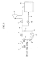
- FIG. 1 is a schematic drawing illustrating a first embodiment of the operation method for a combined plant according to the present invention. Moreover, the components shown in FIG. 1 which are the same as the components shown in FIG. 6 have the same reference numerals as shown in FIG. 6.
- the steam cooling system shown in FIG. 1 comprises the steam drum 1, the superheater 2, the steam pressure regulating valve 3 for GTSCP, the motor valve 4, the steam temperature regulating valve 5 for GTSCP, the gas turbine steam cooling portion 6, the check valve 7, the governor 8, the steam turbine 9, and the condenser 10.
- the steam cooling system shown in FIG. I comprises the steam turbine bypass line 15 and the steam turbine bypass valve 16.
- the steam turbine bypass line 15 connects the inlet pipe 14 which is provided at the upstream of the governor 8 and the condenser 10.
- the gas turbine also starts.
- the steam which is sent in the gas turbine steam cooling portion 6, passes through the steam turbine bypass line 15, and it is then recovered in the condenser 10.
- a steam pressure of the steam drum 1 reaches a certain value.
- a steam line is changed from the auxiliary steam system to a main steam system.
- the combined plant is made be in a normal operation mode by gradually opening the governor 8 and gradually increasing the rotation speed of the steam turbine 9 to a certain value as well, and closing gradually the steam turbine bypass valve 16. Thereby, steam passing through the gas turbine steam cooling portion 6 is recovered in the steam turbine 9.
- the amount of steam passing through the gas turbine steam cooling portion 6 is adjusted by opening and closing the steam turbine bypass valve 16. In other words, when the amount of steam passing though the gas turbine steam cooling portion 6 is small, the amount of steam increases by opening the steam turbine bypass valve 16. In contrast, when the amount is too large, it is decreased by closing the steam turbine bypass valve 16.
- the steam turbine bypass valve 16 opens in every case in which the combined plant is in a starting-up mode, a shut-down mode, a steam turbine emergency stop mode due to an abnormal vibration, decrease in oil pressure, and the like, and an uncontrolled operation mode due to breaking of the governor 8.
- the steam turbine bypass valve 16 is opened and closed.
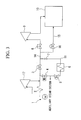
- FIG. 2 is a schematic drawing illustrating a second embodiment of the operation method for a combined plant according to the present invention. Moreover, the components shown in FIG. 2 which are the same as the components shown in FIG. 1 have the same reference numerals as shown in FIG. 1.
- exhaust air from a high pressure area 17 of the steam turbine flows to a position which is at the upstream of the steam turbine bypass valve 16 and downstream of the gas turbine steam cooling portion 6 in a pipe connecting the steam pressure regulating valve 3 for GTSCP and the governor 8.
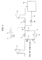
- FIG. 3 is a schematic drawing illustrating a third embodiment of the operation method for a combined plant according to the present invention. Moreover, the components shown in FIG. 3 which are the same as the components shown in FIG. 1 have the same reference numerals as shown in FIG. 3.
- exhaust air from a high pressure area 17 of the steam turbine flows to a position which is at the downstream of the superheater 2 and the upstream of the steam pressure regulating valve 3 for GTSCP and the motor valve 4 in a pipe connecting the superheater 2 and the steam pressure regulating valve 3 for GTSCP.
- FIG. 4 is a schematic drawing illustrating a fourth embodiment of the operation method for a combined plant according to the present invention. Moreover, the components shown in FIG. 4 which are the same as the components shown in FIG. I have the same reference numerals as shown in FIG. 4.
- exhaust air from a high pressure area 17 of the steam turbine flows into a pipe, in a manner similar to that in the second and third embodiments.
- exhaust air from a high pressure area 17 of the steam turbine flows to two positions, one of which is at the upstream of the steam turbine bypass valve 16 and the downstream of the gas turbine steam cooling portion 6 in a pipe connecting the steam pressure regulating valve 3 for GTSCP and the governor 8, and the other of which is at the downstream of the superheater 2 and the upstream of the steam pressure regulating valve 3 for GTSCP and the governor 8 in a pipe connecting the superheater 2 and the steam pressure regulating valve 3 for GTSCP.
- FIG. 5 is a schematic drawing illustrating a fifth embodiment of the operation method for a combined plant according to the present invention. Moreover, the components shown in FIG. 5 which are the same as the components shown in FIG. 1 have the same reference numerals as shown in FIG. 5.
- the position of the steam drum 1 and the superheater 2 is exchanged with the position of the high pressure area 17 of the steam turbine in FIG. 2.
- steam passing through the steam drum 1 and the superheater 2 flows into a position which is at the upstream of the steam turbine bypass valve 16 and downstream of the gas turbine steam cooling portion 6 in a pipe connecting the steam pressure regulating valve 3 for GTSCP and the governor 8, and exhaust air from the high pressure area 17 of the steam turbine flows into the steam pressure regulating valve 3 for GTSCP and the motor valve 4.
Landscapes
- Engineering & Computer Science (AREA)
- Chemical & Material Sciences (AREA)
- Combustion & Propulsion (AREA)
- Mechanical Engineering (AREA)
- General Engineering & Computer Science (AREA)
- Physics & Mathematics (AREA)
- Fluid Mechanics (AREA)
- Engine Equipment That Uses Special Cycles (AREA)
- Control Of Steam Boilers And Waste-Gas Boilers (AREA)
- Control Of Turbines (AREA)
Applications Claiming Priority (2)
| Application Number | Priority Date | Filing Date | Title |
|---|---|---|---|
| JP2001204873 | 2001-07-05 | ||
| JP2001204873A JP4395275B2 (ja) | 2001-07-05 | 2001-07-05 | コンバインドプラントの運転方法 |
Publications (2)
| Publication Number | Publication Date |
|---|---|
| EP1273768A1 true EP1273768A1 (fr) | 2003-01-08 |
| EP1273768B1 EP1273768B1 (fr) | 2013-05-15 |
Family
ID=19041279
Family Applications (1)
| Application Number | Title | Priority Date | Filing Date |
|---|---|---|---|
| EP02014849.0A Expired - Lifetime EP1273768B1 (fr) | 2001-07-05 | 2002-07-03 | Procédé d'opération d'une centrale combinée |
Country Status (4)
| Country | Link |
|---|---|
| US (1) | US6666028B2 (fr) |
| EP (1) | EP1273768B1 (fr) |
| JP (1) | JP4395275B2 (fr) |
| CA (1) | CA2392384C (fr) |
Cited By (1)
| Publication number | Priority date | Publication date | Assignee | Title |
|---|---|---|---|---|
| EP2785984A1 (fr) * | 2011-11-29 | 2014-10-08 | Hucon Swiss AG | Réduction de pression de milieux de travail gazeux |
Families Citing this family (4)
| Publication number | Priority date | Publication date | Assignee | Title |
|---|---|---|---|---|
| US6851265B2 (en) * | 2002-02-19 | 2005-02-08 | Siemens Westinghouse Power Corporation | Steam cooling control for a combined cycle power plant |
| JP4814143B2 (ja) * | 2007-03-29 | 2011-11-16 | 三菱重工業株式会社 | コンバインド発電プラント |
| JP5901194B2 (ja) * | 2011-09-15 | 2016-04-06 | 三菱日立パワーシステムズ株式会社 | ガスタービン冷却システム及びガスタービン冷却方法 |
| US9194248B2 (en) * | 2012-06-07 | 2015-11-24 | General Electric Company | Reheat steam bypass system |
Citations (4)
| Publication number | Priority date | Publication date | Assignee | Title |
|---|---|---|---|---|
| EP0615061A1 (fr) * | 1993-03-11 | 1994-09-14 | Hitachi, Ltd. | Centrale combinée de turbines à gaz et à vapeur |
| EP0764767A2 (fr) * | 1995-09-22 | 1997-03-26 | Kabushiki Kaisha Toshiba | Centrale à cycle combiné |
| EP0933505A2 (fr) * | 1998-01-29 | 1999-08-04 | Mitsubishi Heavy Industries, Ltd. | Système refroidi par vapeur dans une centrale à cycle combiné |
| EP0939204A2 (fr) * | 1998-02-25 | 1999-09-01 | Mitsubishi Heavy Industries, Ltd. | Centrale combinée, méthode pour son fonctionnement, et système de refroidissement à vapeur pour la section haute température de la turbine à gaz |
Family Cites Families (5)
| Publication number | Priority date | Publication date | Assignee | Title |
|---|---|---|---|---|
| KR940004388B1 (ko) | 1989-10-13 | 1994-05-23 | 인터내셔널 비지네스 머신즈 코포레이션 | 지정된 데이타베이스 억세스 플랜 무효화 방법 |
| US6405537B1 (en) * | 1996-06-26 | 2002-06-18 | Hitachi, Ltd. | Single shaft combined cycle plant and operating thereof |
| DE69825858T2 (de) | 1997-06-24 | 2005-09-08 | Mitsubishi Heavy Industries, Ltd. | Dampfkühlungsvorrichtung für gasturbine |
| EP1041261A4 (fr) * | 1997-12-15 | 2003-07-16 | Hitachi Ltd | Turbine a gaz utilisee pour produire de l'energie et systeme mixte de production d'energie |
| JP3652962B2 (ja) * | 1999-11-25 | 2005-05-25 | 三菱重工業株式会社 | ガスタービンコンバインドサイクル |
-
2001
- 2001-07-05 JP JP2001204873A patent/JP4395275B2/ja not_active Expired - Fee Related
-
2002
- 2002-06-28 CA CA002392384A patent/CA2392384C/fr not_active Expired - Fee Related
- 2002-07-02 US US10/187,016 patent/US6666028B2/en not_active Expired - Fee Related
- 2002-07-03 EP EP02014849.0A patent/EP1273768B1/fr not_active Expired - Lifetime
Patent Citations (4)
| Publication number | Priority date | Publication date | Assignee | Title |
|---|---|---|---|---|
| EP0615061A1 (fr) * | 1993-03-11 | 1994-09-14 | Hitachi, Ltd. | Centrale combinée de turbines à gaz et à vapeur |
| EP0764767A2 (fr) * | 1995-09-22 | 1997-03-26 | Kabushiki Kaisha Toshiba | Centrale à cycle combiné |
| EP0933505A2 (fr) * | 1998-01-29 | 1999-08-04 | Mitsubishi Heavy Industries, Ltd. | Système refroidi par vapeur dans une centrale à cycle combiné |
| EP0939204A2 (fr) * | 1998-02-25 | 1999-09-01 | Mitsubishi Heavy Industries, Ltd. | Centrale combinée, méthode pour son fonctionnement, et système de refroidissement à vapeur pour la section haute température de la turbine à gaz |
Cited By (1)
| Publication number | Priority date | Publication date | Assignee | Title |
|---|---|---|---|---|
| EP2785984A1 (fr) * | 2011-11-29 | 2014-10-08 | Hucon Swiss AG | Réduction de pression de milieux de travail gazeux |
Also Published As
| Publication number | Publication date |
|---|---|
| CA2392384C (fr) | 2006-01-17 |
| JP4395275B2 (ja) | 2010-01-06 |
| EP1273768B1 (fr) | 2013-05-15 |
| CA2392384A1 (fr) | 2003-01-05 |
| US20030005702A1 (en) | 2003-01-09 |
| JP2003020911A (ja) | 2003-01-24 |
| US6666028B2 (en) | 2003-12-23 |
Similar Documents
| Publication | Publication Date | Title |
|---|---|---|
| EP0605156B1 (fr) | Méthode de démarrage d'un turbine froide à vapeur dans une centrale combinée | |
| US6178734B1 (en) | Combined cycle power generation plant and operating method thereof | |
| US5471832A (en) | Combined cycle power plant | |
| US6422022B2 (en) | Apparatus and methods for supplying auxiliary steam in a combined cycle system | |
| JP3800384B2 (ja) | コンバインド発電設備 | |
| JP3564242B2 (ja) | 蒸気冷却ガスタービンの冷却蒸気系統システム | |
| US6698182B2 (en) | Gas turbine combined plant | |
| EP0908603B1 (fr) | Centrale a cycle mixte a arbre unique | |
| US6405537B1 (en) | Single shaft combined cycle plant and operating thereof | |
| JP3431435B2 (ja) | コンバインド発電プラントおよびクローズド空気冷却ガスタービンシステム | |
| US11879365B2 (en) | Steam turbine plant and operation method, combined cycle plant and operation method | |
| US6666028B2 (en) | Operation method for combined plant | |
| US20030154721A1 (en) | Steam cooling control for a combined cycle power plant | |
| US6272841B2 (en) | Combined cycle power plant | |
| JP2006161698A (ja) | 蒸気タービンの過負荷運転装置および蒸気タービンの過負荷運転方法 | |
| JP2915885B1 (ja) | ガスタービン複合発電システム | |
| JP5475315B2 (ja) | コンバインドサイクル発電システム | |
| JP3518252B2 (ja) | クローズド蒸気冷却ガスタービンコンバインドプラント及びガスタービンコンバインドプラント | |
| JP2005344528A (ja) | コンバインドサイクル発電プラントおよびその起動運転方法 | |
| JPS60159311A (ja) | 蒸気タ−ビンの起動方法 | |
| EP0978636B1 (fr) | Centrale a cycle combine | |
| JPS62294724A (ja) | タ−ボチヤ−ジヤのタ−ビンケ−シング冷却装置 | |
| JP2003148166A (ja) | コンバインド発電プラントおよびクローズド空気冷却ガスタービンシステム | |
| JPH1193618A (ja) | ガスタービン蒸気冷却系統の蒸気圧制御方法 | |
| JPH0275731A (ja) | タービンプラント |
Legal Events
| Date | Code | Title | Description |
|---|---|---|---|
| PUAI | Public reference made under article 153(3) epc to a published international application that has entered the european phase |
Free format text: ORIGINAL CODE: 0009012 |
|
| 17P | Request for examination filed |
Effective date: 20020703 |
|
| AK | Designated contracting states |
Kind code of ref document: A1 Designated state(s): AT BE BG CH CY CZ DE DK EE ES FI FR GB GR IE IT LI LU MC NL PT SE SK TR |
|
| AX | Request for extension of the european patent |
Free format text: AL;LT;LV;MK;RO;SI |
|
| AKX | Designation fees paid |
Designated state(s): CH DE FR GB IT LI |
|
| 17Q | First examination report despatched |
Effective date: 20050307 |
|
| REG | Reference to a national code |
Ref country code: DE Ref legal event code: R079 Ref document number: 60244951 Country of ref document: DE Free format text: PREVIOUS MAIN CLASS: F01K0023100000 Ipc: F02C0009180000 |
|
| RIC1 | Information provided on ipc code assigned before grant |
Ipc: F02C 7/16 20060101ALI20121029BHEP Ipc: F02C 9/18 20060101AFI20121029BHEP Ipc: F02C 6/18 20060101ALI20121029BHEP Ipc: F01K 23/10 20060101ALI20121029BHEP |
|
| GRAP | Despatch of communication of intention to grant a patent |
Free format text: ORIGINAL CODE: EPIDOSNIGR1 |
|
| GRAS | Grant fee paid |
Free format text: ORIGINAL CODE: EPIDOSNIGR3 |
|
| GRAA | (expected) grant |
Free format text: ORIGINAL CODE: 0009210 |
|
| RIN1 | Information on inventor provided before grant (corrected) |
Inventor name: HYAKUTAKE, YOSHINORI, MITSUBISHI HEAVY INDUSTRIES Inventor name: TAKAHAMA, MASAYUKI, MITSUBISHI HEAVY INDUSTRIES LT Inventor name: TAGUCHI, JYUN, MITSUBISHI HEAVY INDUSTRIES, LTD. |
|
| AK | Designated contracting states |
Kind code of ref document: B1 Designated state(s): CH DE FR GB IT LI |
|
| REG | Reference to a national code |
Ref country code: GB Ref legal event code: FG4D Ref country code: CH Ref legal event code: EP |
|
| REG | Reference to a national code |
Ref country code: DE Ref legal event code: R096 Ref document number: 60244951 Country of ref document: DE Effective date: 20130711 |
|
| PG25 | Lapsed in a contracting state [announced via postgrant information from national office to epo] |
Ref country code: IT Free format text: LAPSE BECAUSE OF FAILURE TO SUBMIT A TRANSLATION OF THE DESCRIPTION OR TO PAY THE FEE WITHIN THE PRESCRIBED TIME-LIMIT Effective date: 20130515 |
|
| REG | Reference to a national code |
Ref country code: CH Ref legal event code: PL |
|
| PLBE | No opposition filed within time limit |
Free format text: ORIGINAL CODE: 0009261 |
|
| STAA | Information on the status of an ep patent application or granted ep patent |
Free format text: STATUS: NO OPPOSITION FILED WITHIN TIME LIMIT |
|
| 26N | No opposition filed |
Effective date: 20140218 |
|
| GBPC | Gb: european patent ceased through non-payment of renewal fee |
Effective date: 20130815 |
|
| REG | Reference to a national code |
Ref country code: FR Ref legal event code: ST Effective date: 20140331 |
|
| PG25 | Lapsed in a contracting state [announced via postgrant information from national office to epo] |
Ref country code: CH Free format text: LAPSE BECAUSE OF NON-PAYMENT OF DUE FEES Effective date: 20130731 Ref country code: LI Free format text: LAPSE BECAUSE OF NON-PAYMENT OF DUE FEES Effective date: 20130731 |
|
| REG | Reference to a national code |
Ref country code: DE Ref legal event code: R097 Ref document number: 60244951 Country of ref document: DE Effective date: 20140218 |
|
| PG25 | Lapsed in a contracting state [announced via postgrant information from national office to epo] |
Ref country code: FR Free format text: LAPSE BECAUSE OF NON-PAYMENT OF DUE FEES Effective date: 20130731 |
|
| PG25 | Lapsed in a contracting state [announced via postgrant information from national office to epo] |
Ref country code: GB Free format text: LAPSE BECAUSE OF NON-PAYMENT OF DUE FEES Effective date: 20130815 |
|
| REG | Reference to a national code |
Ref country code: DE Ref legal event code: R082 Ref document number: 60244951 Country of ref document: DE Representative=s name: PATENTANWAELTE HENKEL, BREUER & PARTNER, DE Ref country code: DE Ref legal event code: R081 Ref document number: 60244951 Country of ref document: DE Owner name: MITSUBISHI HITACHI POWER SYSTEMS, LTD., YOKOHA, JP Free format text: FORMER OWNER: MITSUBISHI HEAVY INDUSTRIES, LTD., TOKYO, JP Ref country code: DE Ref legal event code: R082 Ref document number: 60244951 Country of ref document: DE Representative=s name: PATENTANWAELTE HENKEL, BREUER & PARTNER MBB, DE |
|
| PGFP | Annual fee paid to national office [announced via postgrant information from national office to epo] |
Ref country code: DE Payment date: 20160628 Year of fee payment: 15 |
|
| REG | Reference to a national code |
Ref country code: DE Ref legal event code: R119 Ref document number: 60244951 Country of ref document: DE |
|
| PG25 | Lapsed in a contracting state [announced via postgrant information from national office to epo] |
Ref country code: DE Free format text: LAPSE BECAUSE OF NON-PAYMENT OF DUE FEES Effective date: 20180201 |