EP0933557B1 - Chaíne à dents aux flancs externes convexes pour engagement régulier avec une roue dentée - Google Patents
Chaíne à dents aux flancs externes convexes pour engagement régulier avec une roue dentée Download PDFInfo
- Publication number
- EP0933557B1 EP0933557B1 EP99300548A EP99300548A EP0933557B1 EP 0933557 B1 EP0933557 B1 EP 0933557B1 EP 99300548 A EP99300548 A EP 99300548A EP 99300548 A EP99300548 A EP 99300548A EP 0933557 B1 EP0933557 B1 EP 0933557B1
- Authority
- EP
- European Patent Office
- Prior art keywords
- teeth
- sprocket
- engagement
- link plates
- flank
- Prior art date
- Legal status (The legal status is an assumption and is not a legal conclusion. Google has not performed a legal analysis and makes no representation as to the accuracy of the status listed.)
- Expired - Lifetime
Links
- 230000005540 biological transmission Effects 0.000 claims description 8
- 230000007423 decrease Effects 0.000 description 5
- 230000003247 decreasing effect Effects 0.000 description 4
- 230000015572 biosynthetic process Effects 0.000 description 2
- 238000010276 construction Methods 0.000 description 1
- 238000003780 insertion Methods 0.000 description 1
- 230000037431 insertion Effects 0.000 description 1
Images



Classifications
-
- F—MECHANICAL ENGINEERING; LIGHTING; HEATING; WEAPONS; BLASTING
- F16—ENGINEERING ELEMENTS AND UNITS; GENERAL MEASURES FOR PRODUCING AND MAINTAINING EFFECTIVE FUNCTIONING OF MACHINES OR INSTALLATIONS; THERMAL INSULATION IN GENERAL
- F16G—BELTS, CABLES, OR ROPES, PREDOMINANTLY USED FOR DRIVING PURPOSES; CHAINS; FITTINGS PREDOMINANTLY USED THEREFOR
- F16G13/00—Chains
- F16G13/02—Driving-chains
- F16G13/04—Toothed chains
-
- F—MECHANICAL ENGINEERING; LIGHTING; HEATING; WEAPONS; BLASTING
- F16—ENGINEERING ELEMENTS AND UNITS; GENERAL MEASURES FOR PRODUCING AND MAINTAINING EFFECTIVE FUNCTIONING OF MACHINES OR INSTALLATIONS; THERMAL INSULATION IN GENERAL
- F16H—GEARING
- F16H55/00—Elements with teeth or friction surfaces for conveying motion; Worms, pulleys or sheaves for gearing mechanisms
- F16H55/02—Toothed members; Worms
- F16H55/30—Chain-wheels
- F16H2055/306—Chain-wheels with means providing resilience or vibration damping in chain sprocket wheels
Definitions
- This invention relates to a silent chain power transmission device and, in particular, it relates to a silent chain and sprocket comprising: a silent chain having a plurality of rows of interleaved link plates, each of said link plates having a pair of apertures and at least one pair of teeth said teeth being adapted to contact the teeth of an associated sprocket, a plurality of pivot pins being inserted into said apertures to interconnect said link plates and to permit the articulation of said rows of interleaved link plates, each of said teeth having an outside flank and inside flank; and an associated sprocket for use with said silent chain, said sprocket having a plurality of sprocket teeth disposed about its periphery, said sprocket teeth being constructed and arranged to contact at least some of said silent chain teeth to permit power transmission therebetween;
- a chain and sprocket of this form is described for example in US-A-5267910.
- Silent chains are used conventionally as power transmission chains for automobiles and motorcycles in engine timing systems as well as in transmissions and transfer cases for four-wheel drive vehicles.
- a silent chain is comprised of multiple link plates, each of which has a pair of teeth.
- Each link typically includes a pair of apertures.
- the links are interleaved or connected by connecting pins placed in the link apertures.
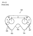
- Figure 8 shows an example of a link plate of a conventional silent chain.
- link plate 100 has a pair of apertures or pinholes 101, 102 for insertion of the connecting pins and a pair of depending or downwardly extending teeth 103, 104 that engage with the teeth a sprocket (not shown).
- the teeth are joined at crotch area 105, which is formed of the inside link flanks.
- Tooth 103 includes inside flank 105a and outside flank 106 and tooth 104 is composed of inside flank 105b and outside flank 107.
- the assignee of the present application has proposed a silent chain that can increase the strength of the link plate without decreasing the strength of the sprocket teeth and according to this proposal a protrusion is formed only in regions A, A' on the outside flank, and not along the entire link flank. Therefore, the strength and thickness of the sprocket teeth are ensured without decreasing the strength of the teeth and the strength of regions A, A' and the entire link plate is improved.
- the inside flank (inner crotch) of the link plate of a certain link row engages first with the sprocket tooth and the point of engagement transfers on the inside flank along the progression of engagement.
- the sprocket tooth engagement point on the inside flank of the link transfers onto the outside flank (outer crotch) of the link plate of the link row which is adjacent to the first link row, and, when engagement progresses, it moves along the outside flank and the engagement ends at a certain point. This final point is the seating point.
- the noise vibration performance of the silent chain (i.e., noise-vibration properties) is thought to be improved if the transfer of load during the engagement can be made smoothly.
- the present invention addresses such a problem and its purpose is to offer a silent chain power transmission device that improves the strength of the link plate of a silent chain without decreasing the strength of the sprocket teeth, making transfer of engagement from the inside flank to the outside flank smoother, thereby improving noise/vibration of the silent chain.
- a silent chain and sprocket of the form initially described characterised in that each of said outside flanks of said teeth of the link plates has a protrusion formed thereon in the vicinity of each of said apertures; said silent chain teeth being constructed and arranged in order that said inside flanks of said teeth of a first row of link plates contact said teeth of said sprocket upon initial engagement of said link plate teeth with said sprocket teeth at a first engagement point on said inside flanks, said engagement of said sprocket teeth on said teeth of said first row link plates terminating at a second engagement point on said inside flanks, said silent chain teeth being constructed and arranged in order that said outside flanks of said teeth of a second row of link plates contact said teeth of said sprocket at a third engagement point along said outside flanks of said second row link plates subsequent to said engagement of said first row link plates with said sprocket teeth at said second engagement point on said outside flanks, said second row of link plates being adjacent to said first row
- each of the outside flanks of the link plates of the silent chain includes a generally flat surface formed on the tip portion of each of the outside flanks.
- a convex curved surface protrudes outwardly from the generally flat surface in the vicinity of each of the apertures.
- a concave curved surface connects the generally flat surface with the convex curved surface. The seating point on the outside surface is located on the concave curved surface.
- the convex curved surface of the outside flank may be arcuately shaped.
- the link plates are back-drive-type link plates and each includes a pair of teeth on both of the opposite sides of the center line of the apertures.
- a projection part is formed only in the vicinity of an aperture or pinhole on the outside flank. Therefore, the thickness of the sprocket teeth is ensured, decrease of sprocket teeth strength is prevented and the strength of the pinhole region of the link plate and that of the entire link plate can be improved.
- engagement starts from the inside flank of the link plate and the engagement point moves to the outside flank of the link plate of the adjacent link row as the engagement progresses. It seats on the outside flank and the point of projection of the engagement endpoint on the inside flank agrees with the engagement-transfer point on the outside flank or is positioned in the vicinity of the engagement transfer point. Therefore, the sprocket teeth do not collide with the outside flank when the engagement point moves from the inside flank to the outside flank.
- the engagement point moves smoothly from the inside flank to the outside flank and transfer of the load from the inside flank to the outside flank is smooth. Thereby, noise due to vibration is lessened or improved.
- the distance between the engagement endpoint on the inside flank and the engagement-transfer point on the outside flank is preferably to be zero or as close to zero as possible.
- the outside flank has a nearly straight flat surface formed at the tip of the tooth.
- a convex surface protrudes outward from the flat surface in the vicinity of the pinhole.
- a concave surface connects the flat surface and the convex surface. It is preferable that the seating point on the outside flank be on the concave surface.
- the convex curved surface is also preferably an arcuate surface and the concave surface is also, preferably, an arcuate surface.
- the link plate can be constructed for a back-surface driving chain and have a pair of teeth on both sides of the pinhole center line.
- Positioning of the seating point on the outside flank of the concave surface reduces surface pressure that acts on the link plate and sprocket teeth during power transmission.
- the surface pressure is great, in general, because of the contact of the flat or convex surface of the link plate with the convex surface of the sprocket teeth.
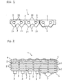
- Figure 1 is a front view of a portion of a silent chain of the present invention.
- Figure 2 is a plan view of the chain of Figure 1.
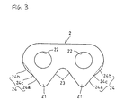
- Figure 3 is an enlarged front view of the link plate of the present invention.
- Figure 4 illustrates the engagement of the link plate of the silent chain of the present invention with the sprocket.
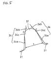
- Figure 5 is an enlargement of a portion of Figure 4.
- Figure 6 illustrates the position of the engagement point on each link plate of the link rows next to each other.
- Figure 7 illustrates another embodiment of the link plate of the present invention in the form of a link for a back-drive chain.
- Figure 8 illustrates a link plate of the prior art.
- link plates 2 each with a pair of depending teeth 21 and a pair of apertures, or pinholes 22, are placed in rows and interleaved to form silent chain 1.
- Link plates 2 are pivotally connected by inserting connecting pin 3 in pinhole 22 of these link plates 2.
- Guide links 4 are placed on the outermost side of link plate 2 in this silent chain.
- Tooth 21 of link plate 2 is comprised of inside flank 23 and outside flank 24, as shown in Figure 3.
- Inside flank 23 has a nearly straight flat surface or slightly curved surface.
- Outside flank 24 has a nearly straight flat surface 24a at the tip of tooth 21 and a convex surface 24b in the vicinity of pinhole 22.
- the convex surface protrudes outward from flat surface 24a and a concave surface 24c of a small radius of curvature connects the above surfaces.
- the double-dotted line in Figure 3 is the extension of flat surface 24a and it indicates the conventional outside flank of a link of the prior art.
- convex surface 24b and concave surface 24c are preferably arcuate surfaces.
- FIG 5 which is an enlargement of part V of Figure 4, shows seating point C on outside flank 24 of link plate 2. As shown in the figure, seating point C is on concave surface 24c of outside flank 24. Placement of seating point C on concave surface 24c reduces the surface pressure that acts on link plate 2 and sprocket teeth 51, thereby improving the durability of the entire chain.
- Convex surface 24b on outside flank 24 forms the only projecting part of the flank and it only projects in the vicinity of pinhole 22 on outside flank 24, which enables thickness t of sprocket teeth 51 to be maintained and not reduced.
- the avoidance of reduction of the thickness of the sprocket tooth prevents the decrease of strength of sprocket teeth 51.
- Figure 6 shows link plates in adjacent rows (i.e., adjacent in the longitudinal direction of the chain) indicated by the solid line and double-dotted line respectively in Figure 4 at some interval between them for the convenience of illustration. That is, link plate 2 is that of a certain link row and link plate 2' is that of the link row which is adjacent to the first link row in the longitudinal direction or the direction of travel of the chain.
- Point B 1 ' in Figure 6 is the engagement transfer point from the inside flank to the outside flank of the conventional silent chain.
- distance s' between points B 0 and B 1 ' is such that s' > s. That is, the engagement point moves from engagement endpoint B on the inside flank to engagement transfer point B 1 ' on the outside flank during engagement transfer from the inside flank to the outside flank in a conventional silent chain, and the distance between projection point B 0 of engagement point B on the outside flank surface and engagement transfer point B 1 ' is large.
- the sprocket teeth collide with the outside flank 24 when the engagement point moves from the inside flank 23 to the outside flank 24 and noise is generated.
- distance s between points B 0 and B 1 is zero or very small (i.e., substantially or nearly coincident), so that collision between outside flank 24 and sprocket teeth 51 does not occur during transfer of the engagement point from engagement endpoint B on the inside flank 23 of link plate 2 to engagement transfer point B 1 on outside flank 24, and transfer of the engagement point from inside flank 23 to outside flank 24 is smooth.
- transfer of load from inside flank 23 to outside flank 24 is smooth for improved noise/vibration performance.
- the present invention is directed to minimization of the distance s between B 0 and B 1 so that the transfer between inside and outside flank is as smooth as possible.
- Figure 7 shows the back-driving link plate.
- link plate 6 has a pair of teeth 61, 61' on both sides of center line L-L' of pinholes 62. Tooth 61 is composed of inside flank 63 and outside flank 64 and tooth 61' is composed of inside flank 63' and outside flank 64'.
- flanks 63, 63' are composed of a nearly straight flat surfaces or slightly curved surfaces.
- Outside flank 64 is composed of a nearly straight flat surface 64a formed at the tip of tooth 61.
- a convex surface 64b formed in the vicinity of pinhole 62 and a concave surface 64c of small radius of curvature connects flat surface 64a and convex surface 64b.
- outside flank 64' is composed of a nearly straight flat surface 64'a formed at the tip of tooth 61'.
- Convex surface 64'b is formed in the vicinity of pinhole 62, and concave surface 64'c of small radius of curvature connect flat surface 64'a and convex surface 64'b.
- the double-dotted line in Figure 7 is the extension of flat surface 64a or 64'a and it indicates a conventional outside flank.
- Convex surfaces 64b, 64'b and concave surfaces 64c, 64'c are preferably arcuate surfaces.
- the engagement mode of the back-driving silent chain having such multiple link plates 6 with sprocket is entirely the same for teeth 61, 61' as the case in Figures 4 and 5. That is, the seating point on outside flank 64 of link plate 6, as regards the sprocket teeth, is positioned on concave surface 64c and the seating point on outside flank 64' of link plate 6, as regards the sprocket teeth, is positioned on concave surface 64'c. Thereby, the surface pressure that acts on the sprocket and outside flanks 64, 64' is reduced.
- the mode of engagement with sprocket teeth of the link row of link plate 6 and link row adjacent to the link row on the side of engagement progression is entirely the same as that in Figure 6. That is, the point of projection of the engagement endpoint on inside flank 63 (or 63') of link plate 6, onto the outside flank of the link plate on the side of engagement progression agrees with the engagement transfer point on the outside flank or it is in the vicinity of the engagement transfer point.
- the projected part is formed only in the vicinity of the pinhole on the outside flank in the silent chain power transmission device of this invention. Therefore, the thickness of the sprocket teeth can be ensured, a decrease of the strength of the sprocket teeth is prevented and the strength of the pinhole region of the link plate and the entire link plate can be improved.
- the inside flank engages with the sprocket teeth at the start of sprocket engagement in this invention
- the engagement point moves from the inside flank to the outside flank as the engagement progresses, and the outside flank seats on the sprocket teeth.
- the point of projection of the engagement endpoint on the inside flank onto the outside flank coincides with the engagement transfer point on the outside flank or is in the vicinity of the engagement transfer point.
- the engagement point transfers smoothly from the inside flank to the outside flank without collision of the sprocket teeth with the outside flank and the transfer of load from the inside flank to the outside flank is smooth. As a result, noise/vibration performance can be improved.
Landscapes
- Engineering & Computer Science (AREA)
- General Engineering & Computer Science (AREA)
- Mechanical Engineering (AREA)
- Gears, Cams (AREA)
- Devices For Conveying Motion By Means Of Endless Flexible Members (AREA)
Claims (6)
- Chaíne et roue dentée comprenant :caractérisées en ce queune chaíne comportant une pluralité de rangées de maillons intercalées (2, 2') chacun desdits maillons ayant une paire d'ouvertures (22, 22) et au moins une paire de dents (21, 21), lesdites dents étant conçues pour contacter la dent (51) d'une roue dentée associée,une pluralité de pivots (3) qui sont insérés dans lesdites ouvertures pour interconnecter lesdits maillons et pour permettre l'articulation desdites rangées des maillons intercalés, chacune desdites dents ayant un flanc extérieur (24) et un flanc intérieur (23) ; etune roue dentée associée (5) pour utilisation avec ladite chaíne, ladite roue dentée comportant une pluralité de dents (51) disposées autour de sa périphérie, lesdites dents étant construites et conçues pour contacter au moins certaines desdites dents de la chaíne pour permettre la transmission de puissance entre celles-ci ;
chacun desdits flancs extérieurs desdites dents des maillons comporte une saillie (24b) formée sur celui-ci au voisinage de chacune desdites ouvertures ;
lesdites dents de chaíne étant construites et conçues afin que lesdits flancs intérieurs (23) desdites dents d'une première rangée de maillons (2) contacte lesdites dents de ladite roue dentée sur engagement initial desdites dents des maillons avec lesdites dents de roue dentée à un premier point d'engagement (A) sur lesdits flancs intérieurs, ledit engagement desdites dents de roue dentée sur lesdites dents desdits maillons de première rangée se terminant à un second point d'engagement (B) sur lesdits flancs intérieurs,
lesdites dents de chaíne étant construites et conçues afin que lesdits flancs extérieurs (24) desdites dents d'une seconde rangée de maillons (2') contactent lesdites dents de ladite roue dentée à un troisième point d'engagement (B0) le long desdits flancs extérieurs de ladite seconde rangée des maillons après ledit engagement des maillons de première rangée avec lesdites dents de roue dentée audit second point d'engagement (B) sur lesdits flancs extérieurs, ladite seconde rangée de maillons (2') étant adjacente à ladite première rangée (2) et précédant ladite première rangée de maillons dans la direction de déplacement de ladite chaíne lorsque mise en prise avec ladite roue dentée,
ledit engagement desdits maillons de seconde rangée avec lesdites dents de roue dentée aboutissant à faire reposer lesdits maillons de seconde rangée sur lesdites dents de roue dentée à un point de repos (C) le long desdits flancs extérieurs desdits maillons de seconde rangée,
ledit second point d'engagement (B) étant au voisinage du troisième point d'engagement (B0). - Chaíne et roue dentée selon la revendication 1, dans lesquelles ledit second point d'engagement (B) coïncide sensiblement avec ledit troisième point d'engagement (B0).
- Chaíne et roue dentée selon la revendication 1 ou 2, dans lesquelles chacun desdits flancs extérieurs desdits maillons de chaíne s'étend depuis une partie de pointe (21) de ladite dent vers une partie au voisinage de ladite ouverture de maillon (22),
ledit flanc extérieur incluant une surface généralement plate (24a) formée sur ladite partie de pointe,
une surface incurvée convexe (24b) dépassant vers l'extérieur depuis ladite surface généralement plate au voisinage de ladite ouverture et à l'opposé de ladite ouverture ; et
une surface incurvée concave (24c) connectant ladite surface généralement plate (24a) avec ladite surface incurvée convexe (24b). - Chaíne et roue dentée selon la revendication 3, dans lesquelles lesdits flancs extérieurs desdits maillons reposent contre lesdites dents de roue dentée à un point de repos (C) sur lesdits flancs extérieurs, ledit point de repos (C) étant placé sur ladite surface incurvée concave (24c).
- Chaíne et roue dentée selon la revendication 3 ou 4, dans lesquelles ladite surface incurvée convexe de flancs extérieurs (24b) est en forme d'arc.
- Chaíne et roue dentée selon l'une quelconque des revendications 1 à 5, dans lesquelles lesdits maillons sont des maillons du type entraínement arrière (6), ladite paire d'ouvertures (62, 62) desdits maillons ayant des points centraux qui définissent une ligne centrale (L) entre celles-ci, chacun desdits maillons incluant une paire de dents (61, 61') sur chacun des côtés opposés de la ligne centrale (L) desdites ouvertures.
Applications Claiming Priority (2)
| Application Number | Priority Date | Filing Date | Title |
|---|---|---|---|
| JP03422798A JP3470036B2 (ja) | 1998-01-29 | 1998-01-29 | サイレントチェーン伝動装置 |
| JP3422798 | 1998-01-29 |
Publications (2)
| Publication Number | Publication Date |
|---|---|
| EP0933557A1 EP0933557A1 (fr) | 1999-08-04 |
| EP0933557B1 true EP0933557B1 (fr) | 2003-09-24 |
Family
ID=12408273
Family Applications (1)
| Application Number | Title | Priority Date | Filing Date |
|---|---|---|---|
| EP99300548A Expired - Lifetime EP0933557B1 (fr) | 1998-01-29 | 1999-01-26 | Chaíne à dents aux flancs externes convexes pour engagement régulier avec une roue dentée |
Country Status (4)
| Country | Link |
|---|---|
| US (1) | US6155945A (fr) |
| EP (1) | EP0933557B1 (fr) |
| JP (1) | JP3470036B2 (fr) |
| DE (1) | DE69911478T2 (fr) |
Families Citing this family (17)
| Publication number | Priority date | Publication date | Assignee | Title |
|---|---|---|---|---|
| JP3402591B2 (ja) * | 2000-09-26 | 2003-05-06 | 株式会社椿本チエイン | サイレントチェーン伝動機構 |
| JP3905322B2 (ja) * | 2001-03-05 | 2007-04-18 | 株式会社椿本チエイン | サイレントチェーン |
| JP4683451B2 (ja) * | 2001-08-03 | 2011-05-18 | 株式会社椿本チエイン | サイレントチェーン伝動機構 |
| DE102004008669A1 (de) * | 2004-02-21 | 2005-09-22 | Rexroth Mecman Gmbh | Metalllasche zur Bildung einer hochbeanspruchbaren Laschenkette und korrespondierende Kettenrad-Laschenketten-Paarung für Zugmittelgetriebe |
| US20050281979A1 (en) * | 2004-06-17 | 2005-12-22 | Toas Murray S | Loose fill insulation product having phase change material therein |
| WO2006036603A1 (fr) * | 2004-09-24 | 2006-04-06 | Cloyes Gear And Products, Inc. | Systeme de chaine a dents inversees avec engrenement sur flanc interieur |
| JP4873943B2 (ja) * | 2005-12-14 | 2012-02-08 | ボルグワーナー・モールステック・ジャパン株式会社 | サイレントチェーン伝動装置 |
| JP4267035B2 (ja) | 2007-01-09 | 2009-05-27 | 株式会社椿本チエイン | サイレントチェーンのリンクプレート |
| DE202007002046U1 (de) * | 2007-02-12 | 2008-06-19 | Iwis Motorsysteme Gmbh & Co. Kg | Nachgeschnittene Zahnlasche |
| JP4368912B2 (ja) * | 2007-07-13 | 2009-11-18 | 株式会社椿本チエイン | エンジン用伝動チェーン |
| JP4944856B2 (ja) * | 2008-08-29 | 2012-06-06 | 本田技研工業株式会社 | サイレントチェーン伝動装置 |
| US8628440B2 (en) | 2008-09-09 | 2014-01-14 | Cloyes Gear And Products, Inc. | Inverted tooth chain and sprocket drive system with reduced meshing impact |
| US9377082B2 (en) | 2008-09-09 | 2016-06-28 | Cloyes Gear And Products, Inc. | Inverted tooth chain and sprocket drive system with reduced meshing impact |
| US8529389B2 (en) * | 2008-09-09 | 2013-09-10 | Cloyes Gear And Products, Inc. | Inverted tooth chain and sprocket drive system with reduced meshing impact |
| US8672786B2 (en) * | 2008-09-09 | 2014-03-18 | Cloyes Gear And Products, Inc. | Inverted tooth chain and sprocket drive system with reduced meshing impact |
| JP4846825B2 (ja) * | 2009-05-28 | 2011-12-28 | 株式会社椿本チエイン | 低干渉音型サイレントチェーン |
| EP3636535B1 (fr) * | 2018-10-09 | 2023-08-02 | Miranda & Irmão Lda. | Système de chaîne d'entraînement |
Family Cites Families (12)
| Publication number | Priority date | Publication date | Assignee | Title |
|---|---|---|---|---|
| FR443581A (fr) * | 1912-05-08 | 1912-09-27 | Les Etablissements De Dion-Bouton Societe Anonyme | Transmission par chaine silencieuse à double face |
| US1560647A (en) * | 1925-05-15 | 1925-11-10 | Whitney Mfg Company | Power-transmitting chain |
| US4759740A (en) * | 1987-04-01 | 1988-07-26 | Borg-Warner Automotive, Inc. | Dual engaging silent chain drive |
| US4854925A (en) * | 1987-11-06 | 1989-08-08 | Gmi Engrg., & Mgmt., Institute | Multi-ratio drive system for sprockets having translating pins |
| US5154674A (en) * | 1990-04-25 | 1992-10-13 | Borg-Warner Automotive Transmission & Engine Components Corporation | Power transmission chain constructed with asymmetrical links |
| JP2915500B2 (ja) * | 1990-06-12 | 1999-07-05 | 前田建設工業株式会社 | プレキャスト鉄筋コンクリート構造物の柱梁接合工法 |
| JPH0444543U (fr) * | 1990-08-20 | 1992-04-15 | ||
| JPH0817766B2 (ja) * | 1990-08-27 | 1996-02-28 | 富士写真光機株式会社 | 内視鏡のアングル部 |
| NL9002535A (nl) * | 1990-11-20 | 1992-06-16 | Multinorm Bv | Maaiinrichting met kettingtransmissie. |
| JPH081312Y2 (ja) * | 1992-03-30 | 1996-01-17 | 株式会社椿本チエイン | 低騒音サイレントチェ−ン |
| JP2560185B2 (ja) * | 1992-11-20 | 1996-12-04 | ボーグ・ワーナー・オートモーティブ株式会社 | 低騒音チエーン伝動装置 |
| JP3122058B2 (ja) * | 1997-03-19 | 2001-01-09 | 株式会社椿本チエイン | 両面噛合型サイレントチェーン |
-
1998
- 1998-01-29 JP JP03422798A patent/JP3470036B2/ja not_active Expired - Lifetime
-
1999
- 1999-01-15 US US09/232,079 patent/US6155945A/en not_active Expired - Lifetime
- 1999-01-26 EP EP99300548A patent/EP0933557B1/fr not_active Expired - Lifetime
- 1999-01-26 DE DE69911478T patent/DE69911478T2/de not_active Expired - Lifetime
Also Published As
| Publication number | Publication date |
|---|---|
| DE69911478T2 (de) | 2004-05-06 |
| JPH11218198A (ja) | 1999-08-10 |
| JP3470036B2 (ja) | 2003-11-25 |
| DE69911478D1 (de) | 2003-10-30 |
| US6155945A (en) | 2000-12-05 |
| EP0933557A1 (fr) | 1999-08-04 |
Similar Documents
| Publication | Publication Date | Title |
|---|---|---|
| EP0933557B1 (fr) | Chaíne à dents aux flancs externes convexes pour engagement régulier avec une roue dentée | |
| JP3839578B2 (ja) | 背面駆動型サイレントチェーン | |
| US5803854A (en) | Silent chain having a sheared link bearing surface | |
| US5628702A (en) | Power transmission chain | |
| EP2324266B1 (fr) | Systeme de transmission par chaine a dents inversees et roue dentee avec impact reduit a l' engrenement | |
| US6186921B1 (en) | Rocker joint silent chain having a joint pin thicker than a corresponding rocker pin | |
| EP0982516A1 (fr) | Chaíne à maillons à dents à engagement par flanc intérieur avec des dents de pignons de formes correspondantes | |
| US6260345B1 (en) | Silent chain | |
| US5562559A (en) | Rocker joint chain with crescent shaped aperture | |
| EP0984200B1 (fr) | Transmission à chaíne dentée | |
| JP3261089B2 (ja) | サイレントチェーン用リンクプレート | |
| US20020025870A1 (en) | Double-sided meshing type silent chain | |
| US20010004615A1 (en) | Chain with improved rocker pin joint structure | |
| EP1253347A2 (fr) | Système de chaine à dents à double action et roue dentéeé,avec roue dentée à profil réduit | |
| US5700217A (en) | Power transmission chain with formed bushing and associated aperture | |
| US5507697A (en) | Minimal pin projection roller chain | |
| US20040097314A1 (en) | Silent chain for smooth seating on sprocket teeth | |
| US6969332B2 (en) | Silent chain | |
| EP1802893A1 (fr) | Systeme de chaine a dents inversees avec engrenement sur flanc interieur | |
| EP0927836B1 (fr) | Chaíne à dents et roue dentée munies de dents à surfaces d'engagement courbes correspondantes | |
| JP3469921B2 (ja) | 動力伝達用チエーン | |
| US20080312020A1 (en) | Plate-link chain | |
| JPH08219237A (ja) | ローラチェーン組立体およびスプロケット組立体 | |
| JPH10281233A (ja) | 動力伝達用チェーン |
Legal Events
| Date | Code | Title | Description |
|---|---|---|---|
| PUAI | Public reference made under article 153(3) epc to a published international application that has entered the european phase |
Free format text: ORIGINAL CODE: 0009012 |
|
| AK | Designated contracting states |
Kind code of ref document: A1 Designated state(s): DE ES FR GB IT SE |
|
| AX | Request for extension of the european patent |
Free format text: AL;LT;LV;MK;RO;SI |
|
| 17P | Request for examination filed |
Effective date: 19991216 |
|
| AKX | Designation fees paid |
Free format text: DE ES FR GB IT SE |
|
| 17Q | First examination report despatched |
Effective date: 20020902 |
|
| GRAH | Despatch of communication of intention to grant a patent |
Free format text: ORIGINAL CODE: EPIDOS IGRA |
|
| RAP1 | Party data changed (applicant data changed or rights of an application transferred) |
Owner name: BORGWARNER MORSE TEC JAPAN K.K. |
|
| GRAS | Grant fee paid |
Free format text: ORIGINAL CODE: EPIDOSNIGR3 |
|
| GRAA | (expected) grant |
Free format text: ORIGINAL CODE: 0009210 |
|
| AK | Designated contracting states |
Kind code of ref document: B1 Designated state(s): DE ES FR GB IT SE |
|
| REG | Reference to a national code |
Ref country code: GB Ref legal event code: FG4D |
|
| REF | Corresponds to: |
Ref document number: 69911478 Country of ref document: DE Date of ref document: 20031030 Kind code of ref document: P |
|
| PGFP | Annual fee paid to national office [announced via postgrant information from national office to epo] |
Ref country code: GB Payment date: 20031211 Year of fee payment: 6 |
|
| PG25 | Lapsed in a contracting state [announced via postgrant information from national office to epo] |
Ref country code: SE Free format text: LAPSE BECAUSE OF FAILURE TO SUBMIT A TRANSLATION OF THE DESCRIPTION OR TO PAY THE FEE WITHIN THE PRESCRIBED TIME-LIMIT Effective date: 20031224 |
|
| PG25 | Lapsed in a contracting state [announced via postgrant information from national office to epo] |
Ref country code: ES Free format text: LAPSE BECAUSE OF FAILURE TO SUBMIT A TRANSLATION OF THE DESCRIPTION OR TO PAY THE FEE WITHIN THE PRESCRIBED TIME-LIMIT Effective date: 20040104 |
|
| ET | Fr: translation filed | ||
| PLBE | No opposition filed within time limit |
Free format text: ORIGINAL CODE: 0009261 |
|
| STAA | Information on the status of an ep patent application or granted ep patent |
Free format text: STATUS: NO OPPOSITION FILED WITHIN TIME LIMIT |
|
| 26N | No opposition filed |
Effective date: 20040625 |
|
| PG25 | Lapsed in a contracting state [announced via postgrant information from national office to epo] |
Ref country code: GB Free format text: LAPSE BECAUSE OF NON-PAYMENT OF DUE FEES Effective date: 20050126 |
|
| GBPC | Gb: european patent ceased through non-payment of renewal fee |
Effective date: 20050126 |
|
| REG | Reference to a national code |
Ref country code: FR Ref legal event code: PLFP Year of fee payment: 18 |
|
| REG | Reference to a national code |
Ref country code: FR Ref legal event code: PLFP Year of fee payment: 19 |
|
| REG | Reference to a national code |
Ref country code: FR Ref legal event code: PLFP Year of fee payment: 20 |
|
| PGFP | Annual fee paid to national office [announced via postgrant information from national office to epo] |
Ref country code: FR Payment date: 20171220 Year of fee payment: 20 |
|
| PGFP | Annual fee paid to national office [announced via postgrant information from national office to epo] |
Ref country code: DE Payment date: 20180109 Year of fee payment: 20 |
|
| PGFP | Annual fee paid to national office [announced via postgrant information from national office to epo] |
Ref country code: IT Payment date: 20180110 Year of fee payment: 20 |
|
| REG | Reference to a national code |
Ref country code: DE Ref legal event code: R071 Ref document number: 69911478 Country of ref document: DE |