EP0933601A2 - Cadre de montage pour filtre - Google Patents
Cadre de montage pour filtre Download PDFInfo
- Publication number
- EP0933601A2 EP0933601A2 EP99630013A EP99630013A EP0933601A2 EP 0933601 A2 EP0933601 A2 EP 0933601A2 EP 99630013 A EP99630013 A EP 99630013A EP 99630013 A EP99630013 A EP 99630013A EP 0933601 A2 EP0933601 A2 EP 0933601A2
- Authority
- EP
- European Patent Office
- Prior art keywords
- frame
- flange
- filter
- walls
- filter assembly
- Prior art date
- Legal status (The legal status is an assumption and is not a legal conclusion. Google has not performed a legal analysis and makes no representation as to the accuracy of the status listed.)
- Withdrawn
Links
- 238000004887 air purification Methods 0.000 claims description 7
- 238000009434 installation Methods 0.000 claims description 6
- 238000007789 sealing Methods 0.000 claims 1
- 239000003570 air Substances 0.000 description 25
- 239000000463 material Substances 0.000 description 2
- 238000004378 air conditioning Methods 0.000 description 1
- 238000003915 air pollution Methods 0.000 description 1
- 239000012080 ambient air Substances 0.000 description 1
- 239000000356 contaminant Substances 0.000 description 1
- 239000002803 fossil fuel Substances 0.000 description 1
- 239000003292 glue Substances 0.000 description 1
- 239000012943 hotmelt Substances 0.000 description 1
- 239000002245 particle Substances 0.000 description 1
- 230000000241 respiratory effect Effects 0.000 description 1
Images


Classifications
-
- F—MECHANICAL ENGINEERING; LIGHTING; HEATING; WEAPONS; BLASTING
- F24—HEATING; RANGES; VENTILATING
- F24F—AIR-CONDITIONING; AIR-HUMIDIFICATION; VENTILATION; USE OF AIR CURRENTS FOR SCREENING
- F24F13/00—Details common to, or for air-conditioning, air-humidification, ventilation or use of air currents for screening
- F24F13/28—Arrangement or mounting of filters
-
- F—MECHANICAL ENGINEERING; LIGHTING; HEATING; WEAPONS; BLASTING
- F24—HEATING; RANGES; VENTILATING
- F24F—AIR-CONDITIONING; AIR-HUMIDIFICATION; VENTILATION; USE OF AIR CURRENTS FOR SCREENING
- F24F1/00—Room units for air-conditioning, e.g. separate or self-contained units or units receiving primary air from a central station
- F24F1/0007—Indoor units, e.g. fan coil units
- F24F1/0071—Indoor units, e.g. fan coil units with means for purifying supplied air
-
- Y—GENERAL TAGGING OF NEW TECHNOLOGICAL DEVELOPMENTS; GENERAL TAGGING OF CROSS-SECTIONAL TECHNOLOGIES SPANNING OVER SEVERAL SECTIONS OF THE IPC; TECHNICAL SUBJECTS COVERED BY FORMER USPC CROSS-REFERENCE ART COLLECTIONS [XRACs] AND DIGESTS
- Y10—TECHNICAL SUBJECTS COVERED BY FORMER USPC
- Y10S—TECHNICAL SUBJECTS COVERED BY FORMER USPC CROSS-REFERENCE ART COLLECTIONS [XRACs] AND DIGESTS
- Y10S55/00—Gas separation
- Y10S55/31—Filter frame
Definitions
- This invention relates to an air purifier unit and, in particular, to a high efficiency filter assembly for use in a portable air purifying unit.
- HEPA high efficiency particle arrestor
- a filter assembly for installation in an air purification unit that has a rectangular air inlet to the system blower.
- the filter assembly includes a rectangular frame for housing a HEPA filter pack.
- An L-shaped flange surrounds the frame and opens toward the front of the frame.
- the flange is adapted to receive the front edge of the blower inlet therein.
- the front edge of the air inlet closes against the back wall of the flange to prevent air drawn into the assembly by the blower from leaking by the flange.
- the flange is extended outwardly above the top wall of the filter frame to provide a handle for carrying the filter assembly and facilitating installation and removal of the assembly from the unit.
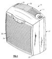
- the unit includes a housing 11 containing a main support member 12 for supporting the component parts of the air purifying equipment and the housing covers that enclose the equipment.
- the support member is a rectangular shaped element containing a top wall 14, a bottom wall 15 and opposed side walls 16.
- An inner wall 17 is integrally joined to the other walls and has a central orifice 19 formed therein.
- a blower motor 20 is mounted upon a bracket on the front face of the inner wall.
- a scroll 23 is formed in the back face of the inner wall around the orifice and the motor shaft 24 is arranged to pass through the orifice into the scroll.
- a fan 25 is secured to the motor shaft and is fully contained inside the scroll.
- the front edge section of the main support frame serves as the air inlet to the blower.
- a rear cover 27 is affixed to the back of the support frame that contains a back panel 28 that encloses both the back of the scroll and a scroll discharge opening 29 formed in the top wall of the main support member to create an airtight passage therethrough.
- a top cover 30 is secured to the top wall of the support member which contains an air discharge vent 31.
- a front cover 32 is removably fitted over the front of the support member and coacts with the other covers to close the housing.
- the front panel 33 of the front cover contains an air inlet vent 34 which permits ambient air to be drawn by the fan into the housing.
- a filter assembly is removably contained within the air inlet section of the support member and a includes rectangular filter frame 36 that is slidably received in the rectangular shaped air inlet to the blower.
- the filter assembly includes a molded frame 36 having a top wall 38, a bottom wall 39 and a pair of opposed side walls 40.
- An inwardly extended lip 41 depends from the front edge of each wall to provide additional strength and rigidity to the filter frame.
- a filter pack 45 is mounted inside the filter frame and is sealed to the interior surfaces of the frame walls by means of a hot-melt glue 46 (Fig. 8) to provide an airtight joint between the filter frame and the filter pack.
- a HEPA filter 47 is contained in the pack for removing fine particulates and other contaminants from the air stream drawn through the filter by the blower. As will be explained in greater detail below, the filter pack can be easily removed from the blower assembly to be cleaned or replaced depending on the nature of the filter material.
- An L-shaped flange 50 (Fig. 7) surrounds the outside of the filter frame.
- the flange includes a continuous back wall 51 that is perpendicularly aligned with the walls of the frame and a continuous upper wall 52 that parallels the walls of the frame.
- the flange opens towards the front of the frame and is adapted to slidably receive therein the rectangular front edge of the air inlet to the blower at the front of the main support member.
- the front edge of the air inlet closes against the back wall of the flange to form a seal for preventing the air that is being drawn through the filter from escaping from the filter assembly.
- the upper wall 60 (Fig. 8) of the flange is offset a greater distance from the top wall 61 of the filter frame than from the other sections of the flange. Sufficient room is provided between the upper wall of the flange and the top wall of the filter frame to allow the flange in this region to be securely grasped to facilitate installation and removal of the assembly from the blower unit as well as carrying the assembly.
- Ribs 63 are mounted on the top wall of the filter frame inside the flange. Sufficient space is provided between the top surfaces of the ribs and the inside surface of the flange upper surfaces to permit the top wall of the main support member to pass therebetween. The ribs help to locate and align the frame with respect to the blower air inlet during installation of the filter assembly. A generous radius 65 is formed at the top front edge of each rib to help guide the front edge of the blower air inlet under the flange. A close sliding fit is provided between the top of the flange and the remaining walls of the main support frame so that the filter frame fits snugly over the air inlet of the blower.
- a tab 70 is mounted upon the front lip associated with the top wall of the filter frame. At assembly, the tab that is arranged to pass through an opening 71 in the support member into contact with a safety switch 73 contained behind the opening to close the switch and thus provide power to the blower motor. Removal of the filter frame from the unit opens the switch thus disconnecting the motor from its power supply.
- the parts of the filter frame which include the walls, the flange, the front lip, the ribs and the tab are all integrally molded from a high strength plastic.
Landscapes
- Engineering & Computer Science (AREA)
- Chemical & Material Sciences (AREA)
- Combustion & Propulsion (AREA)
- Mechanical Engineering (AREA)
- General Engineering & Computer Science (AREA)
- Filtering Of Dispersed Particles In Gases (AREA)
Applications Claiming Priority (2)
| Application Number | Priority Date | Filing Date | Title |
|---|---|---|---|
| US17355 | 1998-02-02 | ||
| US09/017,355 US5980600A (en) | 1998-02-02 | 1998-02-02 | Filter mounting frame |
Publications (2)
| Publication Number | Publication Date |
|---|---|
| EP0933601A2 true EP0933601A2 (fr) | 1999-08-04 |
| EP0933601A3 EP0933601A3 (fr) | 2001-09-26 |
Family
ID=21782120
Family Applications (1)
| Application Number | Title | Priority Date | Filing Date |
|---|---|---|---|
| EP99630013A Withdrawn EP0933601A3 (fr) | 1998-02-02 | 1999-01-22 | Cadre de montage pour filtre |
Country Status (3)
| Country | Link |
|---|---|
| US (1) | US5980600A (fr) |
| EP (1) | EP0933601A3 (fr) |
| AU (1) | AU734356B2 (fr) |
Families Citing this family (13)
| Publication number | Priority date | Publication date | Assignee | Title |
|---|---|---|---|---|
| WO2001003799A1 (fr) * | 1999-07-07 | 2001-01-18 | The Holmes Group, Inc. | Epurateur d'air |
| US6610118B2 (en) | 1999-07-07 | 2003-08-26 | The Holmes Group, Inc. | Air purifier |
| US6461396B1 (en) | 1999-07-07 | 2002-10-08 | The Holmes Group, Inc. | Air purifier |
| US6319300B1 (en) * | 2000-07-12 | 2001-11-20 | Liou-Win Chen | Filter assembly of an air filter |
| US20040076514A1 (en) * | 2002-10-16 | 2004-04-22 | Sunonwealth Electric Machine Industry Co., Ltd. | Suspension type heat-dissipation fan |
| US20060021932A1 (en) * | 2004-07-26 | 2006-02-02 | Darnell Justin R | Integrated flat panel filter and housing |
| USD568452S1 (en) * | 2006-03-17 | 2008-05-06 | Lux International Ag | Air purifier |
| WO2009096984A1 (fr) * | 2008-02-01 | 2009-08-06 | Carrier Corporation | Bride de cadre pouvant être fixé sur une cartouche de filtre pour former un ensemble de filtre |
| US9034068B2 (en) * | 2012-06-05 | 2015-05-19 | Clarcor Air Filtration Products, Inc. | Box filter with orientation device |
| USD802725S1 (en) | 2014-02-14 | 2017-11-14 | Access Business Group International Llc | Air treatment system |
| USD846105S1 (en) | 2014-02-14 | 2019-04-16 | Access Business Group International Llc | Air treatment system |
| USD825046S1 (en) | 2017-01-09 | 2018-08-07 | Access Business Group International Llc | Air treatment system |
| CN214581638U (zh) * | 2021-02-07 | 2021-11-02 | 深圳市安拓浦科技有限公司 | 壁挂式空气净化机 |
Family Cites Families (9)
| Publication number | Priority date | Publication date | Assignee | Title |
|---|---|---|---|---|
| SE390879B (sv) * | 1975-01-31 | 1977-01-31 | Electrolux Ab | Dammsugare med avkennare for dammsamlare |
| DE3150392A1 (de) * | 1981-12-16 | 1983-06-23 | Delbag-Luftfilter Gmbh, 1000 Berlin | Kompaktes universal-grossflaechenfiltersystem nach dembaukastenprinzip zur luftreinigung |
| US4773922A (en) * | 1987-07-22 | 1988-09-27 | The United States Of America As Represented By The United States Department Of Energy | Remotely serviced filter and housing |
| JPH04193318A (ja) * | 1990-11-27 | 1992-07-13 | Matsushita Electric Ind Co Ltd | 空気清浄器のフィルター取付装置 |
| US5240478A (en) * | 1992-06-26 | 1993-08-31 | Messina Gary D | Self-contained, portable room air treatment apparatus and method therefore |
| US5378254A (en) * | 1993-10-15 | 1995-01-03 | Vaportek, Inc. | Filter sensing apparatus and filter therefor |
| US5512086A (en) * | 1994-06-14 | 1996-04-30 | Appliance Development Corporation | High-efficiency air filtering apparatus |
| JPH09155135A (ja) * | 1995-12-14 | 1997-06-17 | Toyoda Gosei Co Ltd | エアクリーナー |
| US5674303A (en) * | 1996-01-16 | 1997-10-07 | Ter Horst; Dirk Dieter Hans | Filter assembly |
-
1998
- 1998-02-02 US US09/017,355 patent/US5980600A/en not_active Expired - Fee Related
-
1999
- 1999-01-22 EP EP99630013A patent/EP0933601A3/fr not_active Withdrawn
- 1999-02-01 AU AU14274/99A patent/AU734356B2/en not_active Ceased
Also Published As
| Publication number | Publication date |
|---|---|
| EP0933601A3 (fr) | 2001-09-26 |
| AU1427499A (en) | 1999-08-19 |
| AU734356B2 (en) | 2001-06-14 |
| US5980600A (en) | 1999-11-09 |
Similar Documents
| Publication | Publication Date | Title |
|---|---|---|
| US6017375A (en) | Air purifier unit | |
| AU734356B2 (en) | Filter mounting frame | |
| US4838910A (en) | Air driven filtration system | |
| CA2371038C (fr) | Aspirateur perfectionne | |
| US5417729A (en) | Portable modular air cleaning system | |
| US6149699A (en) | Method and apparatus relating to disposable filter modules for filtering air containing hazardous substances | |
| CZ280970B6 (cs) | Vzduchový filtr pro vnitřní prostor motorových vozidel | |
| CA1251683A (fr) | Dispositif de filtrage pour imprimantes a grande vitesse | |
| CA2144921A1 (fr) | Hotte aspirante auto-nettoyante | |
| US6004367A (en) | Front access cover for air purifier | |
| US6030426A (en) | Lifting handle for air purifier | |
| EP0608034B1 (fr) | Dispositif de filtration | |
| US6000559A (en) | Mount for circuit board | |
| US4827901A (en) | Filter base for forced air furnace | |
| US3930818A (en) | Air cleaner | |
| KR20190000367U (ko) | 실외 공기흡입구가 형성된 공기정화기 | |
| US4558636A (en) | Protective shelter flow control apparatus | |
| US20050013711A1 (en) | Exhaust fan | |
| GB2167680A (en) | Environmental cleaning machine | |
| JPH10216561A (ja) | 空気清浄装置 | |
| JPH0938449A (ja) | 装置本体部取付け型空調装置 | |
| JPH0129723B2 (fr) | ||
| US6821200B2 (en) | Low-cost/disposable hazardous material handling and anti-contamination hoods | |
| JPH11118222A (ja) | 換気装置 | |
| JP3664107B2 (ja) | 空調換気扇 |
Legal Events
| Date | Code | Title | Description |
|---|---|---|---|
| PUAI | Public reference made under article 153(3) epc to a published international application that has entered the european phase |
Free format text: ORIGINAL CODE: 0009012 |
|
| AK | Designated contracting states |
Kind code of ref document: A2 Designated state(s): AT BE CH CY DE DK ES FI FR GB GR IE IT LI LU MC NL PT SE Kind code of ref document: A2 Designated state(s): DE ES FR GB IT |
|
| AX | Request for extension of the european patent |
Free format text: AL;LT;LV;MK;RO;SI |
|
| PUAL | Search report despatched |
Free format text: ORIGINAL CODE: 0009013 |
|
| AK | Designated contracting states |
Kind code of ref document: A3 Designated state(s): AT BE CH CY DE DK ES FI FR GB GR IE IT LI LU MC NL PT SE |
|
| AX | Request for extension of the european patent |
Free format text: AL;LT;LV;MK;RO;SI |
|
| RIC1 | Information provided on ipc code assigned before grant |
Free format text: 7F 24F 13/28 A, 7F 24F 3/16 B |
|
| 17P | Request for examination filed |
Effective date: 20020320 |
|
| AKX | Designation fees paid |
Free format text: DE ES FR GB IT |
|
| GRAP | Despatch of communication of intention to grant a patent |
Free format text: ORIGINAL CODE: EPIDOSNIGR1 |
|
| STAA | Information on the status of an ep patent application or granted ep patent |
Free format text: STATUS: THE APPLICATION IS DEEMED TO BE WITHDRAWN |
|
| 18D | Application deemed to be withdrawn |
Effective date: 20040524 |