EP0933645A2 - Construction d'un assemblage de bobines à gradient blindées pour l'imagerie par résonance magnétique au moyen d'une analyse par éléments finis - Google Patents
Construction d'un assemblage de bobines à gradient blindées pour l'imagerie par résonance magnétique au moyen d'une analyse par éléments finis Download PDFInfo
- Publication number
- EP0933645A2 EP0933645A2 EP98310690A EP98310690A EP0933645A2 EP 0933645 A2 EP0933645 A2 EP 0933645A2 EP 98310690 A EP98310690 A EP 98310690A EP 98310690 A EP98310690 A EP 98310690A EP 0933645 A2 EP0933645 A2 EP 0933645A2
- Authority
- EP
- European Patent Office
- Prior art keywords
- coil assembly
- gradient
- coil
- magnetic
- continuous current
- Prior art date
- Legal status (The legal status is an assumption and is not a legal conclusion. Google has not performed a legal analysis and makes no representation as to the accuracy of the status listed.)
- Withdrawn
Links
- 238000002595 magnetic resonance imaging Methods 0.000 title claims abstract description 12
- 238000004458 analytical method Methods 0.000 title claims abstract description 11
- 238000013461 design Methods 0.000 title description 27
- 238000009826 distribution Methods 0.000 claims abstract description 28
- 238000000034 method Methods 0.000 claims abstract description 26
- 238000003384 imaging method Methods 0.000 claims abstract description 21
- 238000013459 approach Methods 0.000 claims abstract description 16
- 230000000712 assembly Effects 0.000 claims abstract description 9
- 238000000429 assembly Methods 0.000 claims abstract description 9
- 238000004804 winding Methods 0.000 claims description 6
- 230000004323 axial length Effects 0.000 claims description 5
- 238000010276 construction Methods 0.000 claims description 4
- 230000004907 flux Effects 0.000 claims description 3
- 239000004020 conductor Substances 0.000 claims description 2
- 230000008901 benefit Effects 0.000 description 6
- 230000000694 effects Effects 0.000 description 5
- 206010009244 Claustrophobia Diseases 0.000 description 4
- 238000004519 manufacturing process Methods 0.000 description 4
- 208000019899 phobic disease Diseases 0.000 description 4
- 230000003993 interaction Effects 0.000 description 3
- 210000003484 anatomy Anatomy 0.000 description 2
- 235000009508 confectionery Nutrition 0.000 description 2
- 238000011156 evaluation Methods 0.000 description 2
- 239000011159 matrix material Substances 0.000 description 2
- RYGMFSIKBFXOCR-UHFFFAOYSA-N Copper Chemical compound [Cu] RYGMFSIKBFXOCR-UHFFFAOYSA-N 0.000 description 1
- 230000005540 biological transmission Effects 0.000 description 1
- 230000015572 biosynthetic process Effects 0.000 description 1
- 238000004364 calculation method Methods 0.000 description 1
- 229910052802 copper Inorganic materials 0.000 description 1
- 239000010949 copper Substances 0.000 description 1
- 230000003247 decreasing effect Effects 0.000 description 1
- 230000002939 deleterious effect Effects 0.000 description 1
- 230000005284 excitation Effects 0.000 description 1
- 230000006870 function Effects 0.000 description 1
- 238000010237 hybrid technique Methods 0.000 description 1
- 238000013152 interventional procedure Methods 0.000 description 1
- 239000000463 material Substances 0.000 description 1
- 230000007246 mechanism Effects 0.000 description 1
- 230000004048 modification Effects 0.000 description 1
- 238000012986 modification Methods 0.000 description 1
- 238000012887 quadratic function Methods 0.000 description 1
- 230000009467 reduction Effects 0.000 description 1
- 238000004904 shortening Methods 0.000 description 1
- 230000002123 temporal effect Effects 0.000 description 1
Images




Classifications
-
- G—PHYSICS
- G01—MEASURING; TESTING
- G01R—MEASURING ELECTRIC VARIABLES; MEASURING MAGNETIC VARIABLES
- G01R33/00—Arrangements or instruments for measuring magnetic variables
- G01R33/20—Arrangements or instruments for measuring magnetic variables involving magnetic resonance
- G01R33/28—Details of apparatus provided for in groups G01R33/44 - G01R33/64
- G01R33/38—Systems for generation, homogenisation or stabilisation of the main or gradient magnetic field
- G01R33/385—Systems for generation, homogenisation or stabilisation of the main or gradient magnetic field using gradient magnetic field coils
-
- G—PHYSICS
- G01—MEASURING; TESTING
- G01R—MEASURING ELECTRIC VARIABLES; MEASURING MAGNETIC VARIABLES
- G01R33/00—Arrangements or instruments for measuring magnetic variables
- G01R33/20—Arrangements or instruments for measuring magnetic variables involving magnetic resonance
- G01R33/28—Details of apparatus provided for in groups G01R33/44 - G01R33/64
- G01R33/42—Screening
- G01R33/421—Screening of main or gradient magnetic field
- G01R33/4215—Screening of main or gradient magnetic field of the gradient magnetic field, e.g. using passive or active shielding of the gradient magnetic field
Definitions
- the present invention relates to electro-magnetic shielding. It finds particular application in conjunction with gradient coils for magnetic resonance imaging apparatus and will be described with particular reference thereto. However, it is to be appreciated that the present invention also finds application in conjunction with systems which employ gradient magnetic fields and other applications in which electro-magnetic shielding is desired.
- gradient coil assemblies are commonly pulsed with electrical current pulses to produce magnetic gradients across the main magnetic field in the vicinity of an imaging region.
- electrical current pulses are produced which interact with external metallic structures such as the magnet cold shields, the magnet dewar, and the like. The interaction generates eddy currents in the affected structures.
- These eddy currents in turn, generate eddy magnetic fields which have a deleterious effect on the temporal and spatial quality of the magnetic field in the vicinity of the imaging region and, hence, in the resultant image quality.
- the eddy current problem is often addressed by placing an active shielding coil between the primary gradient coil and the affected structure.
- the shielding coils are designed to substantially zero or cancel the magnetic field external to itself thereby preventing the formation of eddy currents in potentially vulnerable structures.
- Previously methods for production for magnetic gradients in magnetic resonance imaging systems consisted of winding discrete coils in a bunched or distributed fashion on an electrically insulating hollow cylindrical former and driving the coils with a current source of limited voltage.
- Conventional bunched coil designs include the Maxwell and the Modified Maxwell Pair for z-gradient production, and the Golay or Modified Golay (multi-arc) Saddle Coils for x and/or y-gradient production.
- these methods consisted of iteratively placing coil loops or arcs on the cylindrical former until the desired gradient strength, gradient uniformity, and inductance (related to stored energy) were achieved.
- More recent methods of generating magnetic fields in magnetic resonance imaging systems utilize an "inverse approach.”
- the gradient magnetic field is forced to match predetermined values at specified spatial locations inside the imaging volume and a continuous current density is calculated which is capable of producing such a field.
- the "inverse approach” method assumes that the primary gradient coil has finite dimensions while those of the secondary or shield coil are left unrestricted (infinite).
- an apodization algorithm is performed on the continuous current density of the shield coil in order to restrain it to desirable dimensions.
- the Stream Function technique is employed in order to obtain discrete current patterns for both coils.
- Application of the Biot-Savart law to the discrete current pattern ensures that the discretization procedure was proper.
- This approach created generally more energy efficient gradient coil assemblies with higher gradient strengths and faster slew rates as compared to the "forward approach” method.
- the gradient coil assembly can not be appropriately centred. That is to say, when the gradient coil assembly's diameter is large enough to encompass a subject's shoulders it is too far radially from the subject's head, and conversely, when the diameter is sufficiently close to the head, the shoulders interfere with an end of the coil such that the isocentre of the gradient coil is not properly aligned with the area of interest in the head.
- U.S. Patent No. 5,378,989 to Barber et al. presents yet another flared gradient coil assembly for use with open magnet systems.
- the flared portions are not at the ends of a cylindrical coil. Rather, the flared portions are near the isocentre. This prohibits the assembly from being used with a closed bore magnet.
- the design restricts the flare to a 90° angle and is based on a "forward approach" which results in decreased performance.
- the gradient shielding coil For interventional procedures and like applications where patient access is desirable, it is advantageous to design the gradient shielding coil such that its dimensions do not exceed those of the flared primary gradient coil. In this manner, patient access can be maximized and the feeling of openness can reduce patient claustrophobia.
- previous methods and prior art suffer the drawback that as the shielding coil length approaches that of the primary coil, increased levels of eddy current effects within the imaging region deteriorate image quality.
- the dimensions of the shielding coil are substantially larger than those of the primary coil such that the level of patient access is encumbered and an increased level of patient claustrophobia is experienced.
- a method of designing shielded gradient coil assemblies for magnetic resonance imaging systems includes calculating a first continuous current distribution for a three dimensional construction using an inverse approach.
- the first continuous current distribution is confined within predetermined finite geometric boundaries of the three dimensional construction and generates a magnetic gradient field across an imaging region.
- the magnetic gradient field is constrained to predetermined values at specified spatial locations within the imaging region.
- a second continuous current distribution for a shielding coil is calculated using finite element analysis.
- the second continuous current distribution is confined within predetermined finite geometric boundaries of the shielding coil.
- the second continuous current distribution generates a magnetic field which substantially cancels in an area outside a region defined by the shielding coil a fringe magnetic field generated by the first continuous current density.
- a magnetic resonance scanner in accordance with another aspect of the present invention, includes a main magnet for generating a main magnetic field through an examination region.
- the main magnet is arranged such that its geometry defines the examination region.
- a couch supports a subject to be examined within the examination region.
- a radio frequency coil is disposed adjacent the examination region for transmitting radio frequency signals into the examination region and selectively exciting dipoles disposed therein.
- a radio frequency transmitter drives the radio frequency coil.
- a receiver receives magnetic resonance signals from resonating dipoles within the examination region.
- An image processor reconstructs an image representation from the received magnetic resonance signals for display on a human readable display.
- the scanner also includes a gradient coil assembly for generating substantially linear magnetic gradients across the main magnetic field.
- the gradient coil assembly includes at least one cylindrical primary coil assembly with flared ends disposed about the examination region including an array of conductive coil loops arranged on a finite former such that a current density flowing thereon generates the substantially linear magnetic gradients.
- the gradient coil assembly also includes at least one cylindrical secondary coil assembly disposed about the primary coil assembly between the primary coil assembly and the main magnet including an array of conductive coil loops arranged on a finite former such that a current density flowing thereon substantially cancels magnet flux density outside an area defined by the secondary coil assembly.
- the current density of the secondary coil assembly counters eddy currents that would be generated in the secondary coil assembly by the primary coil assembly.
- a main magnetic field control 10 controls superconducting or resistive magnets 12 such that a substantially uniform, temporally constant main magnetic field is created along a z axis through an examination region 14.
- a couch (not illustrated) suspends a subject to be examined within the examination region 14 .
- a magnetic resonance echo means applies a series of radio frequencies (RF) and magnetic field gradient pulses to invert or excite magnetic spins, induce magnetic resonance, refocus magnetic resonance, manipulate magnetic resonance, spatially and otherwise encode the magnetic resonance, to saturate spins, and the like to generate magnetic resonance imaging and spectrography sequences.
- RF radio frequencies
- gradient pulse amplifiers 20 apply current pulse to selected ones or pairs of gradient coil assemblies 22 to create magnetic field gradients along x, y, and z axes of the examination region 14.
- a digital radio frequency transmitter 24 transmit radio frequency pulses or pulse packets to a whole-body RF coil 26 to transmit RF pulses into the examination region.
- a typical radio frequency pulse is composed of a packet of immediately contiguous pulse segments of short duration which taken together with each other and any applied gradients achieve a selected magnetic resonance manipulation. For whole-body applications, the resonance signals are commonly picked up by the whole-body RF coil 26.
- specialized radio frequency coils are placed contiguous to the selected region.
- an insertable RF coil may be inserted surrounding a selected region at the isocentre of the bore.
- the insertable RF coil is used to excite magnetic resonance and receive magnetic resonance signals emitting, from the patient in the region being examined.
- the insertable RF coil can be used to only receive resonance signals introduced by whole-body coil RF transmissions.
- the resultant radio frequency signals are picked up by the whole-body RF coil 26 , the insertable RF coil, or other specialized RF coils and demodulated by a receiver 30 , preferably a digital receiver.
- a sequence control circuit 40 controls the gradient pulse amplifiers 20 and the transmitter 24 to generate any of a plurality of multiple echo sequences such as echo planar imaging, echo volume imaging, gradient and spin echo imaging, fast spin echo imaging, and the like.
- the receiver 30 receives a plurality of data lines in rapid succession following each RF excitation pulse.
- the radio frequency signals received are demodulated and reconstructed into an image representation by a reconstruction processor 50 which applies a two dimensional Fourier transform or other appropriate reconstruction algorithm.
- the image may represent a planar slice through the patient, an array of parallel planar slices, a three dimensional volume, of the like.
- the image is then stored in an image memory 52 where it may be accessed by a display, such as a video monitor 54 which provides a human readable display of the resultant image.
- the conventional design for shielded gradient coil assemblies has generally been based upon the assumption that the total length of the shielding coil is unrestricted and thus its current density is assumed as infinitely extended. Consequently, as "infinite" shielding coils are not available for practical applications, the current density was subsequently apodized or truncated to fit on appropriate finite length elements.
- the technique employed herein involves the design of a shielded gradient coil configuration whereby the current for the shielding coil is initially restricted within the boundaries of a shielding coil having a finite length.
- the geometrical configuration of the shielded gradient coil assembly 22 designed such that the current density is initially contained within the finite boundaries of the shielding coil is shown.
- the length of the primary coil 60 is denoted as L a
- the axial length of the flared portion is denoted as L f
- the length of the flared portion along its surface is defined as L c
- the length of the secondary coil 62 is denoted as L b .
- the radius of the cylindrical portion of the primary coil 60 is denoted as a while the radius of the shielding coil 62 is denoted as b.
- the flared portion of the primary coil is a conical surface with starting radius a and final radius a + ⁇ .
- Each combination of L c , L f , and ⁇ defines a distinct conical surfaces.
- the design of a gradient coil where the z component of the magnetic field varies substantially linearly along the x direction initially involves the design of the primary coil 60 based on an inverse approach methodology. Initially, the current of the primary coil is modelled to lie on a 2D cylindrical surface. For this x-gradient coil, the gradient magnetic field is anti-symmetric in the x direction around the geometric centre of the coil, while it is symmetric along the y and z directions.
- J a ( r ) [ j ⁇ a ( ⁇ , z ) ⁇ ⁇ + j z a ( ⁇ , z ) ⁇ z ] ⁇ ( ⁇ - a )
- ⁇ ( ⁇ -a) is the restriction that confines the electrical current on a cylinder surface with radius a.
- the values are obtained for the Fourier coefficients for the current density. of the primary coil 60 , which determines its continuous current distribution.
- the continuous current distribution is discretized and the Biot-Savart law is applied to the discrete current pattern in order to verify the validity of the earlier minimization.
- the finite element model was extended axially to 5.0 m and radially to 2.5 m. At these locations, the vector potential was set to zero.
- the primary coil 60 is considered as a layer with a cylindrical portion inner radius of 0.34096 m and an outer radius of 0.343320 m. This provides for a mean radius of 0.342138 m which corresponds to the radius a previously determined for the cylindrical portion of the primary coil 60 .
- the primary coil 60 has a thickness equal to 0.00236 m and a half length, of 0.6635 m.
- the secondary coil has an inner radius of 0.432354 m and an outer radius of 0.433354 m while its half length, is 0.663504 m.
- the half length of both the primary and secondary coils are chosen to be substantially identical.
- the finite element analysis code has been set in a parametric way which permits changes to the dimensions of the primary and secondary coils to fit within desired design parameters. Given the dimensions of the layer that corresponds to the primary coil 60 , the current load using the Fourier coefficient expansion as it was previously derived is applied thereto.
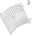
- FIGURE 4 illustrates the current pattern behaviour for the primary coil 60 .
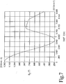
- the net fringe magnetic field maximum occurs at the coil's isocentre and has a value of approximately 12.4 ⁇ T.
- FIGURE 8 an evaluation of the fringe magnetic field outside the shielding coil for a conventionally designed coil having a truncated infinite shield current as previously described and having no flared ends on the primary coil is illustrated.
- the shielding coil in this case is dimensionally similar to the one designed using the finite element analysis previously described but was designed with an infinitely extended current that was truncated to fit an axial half length of 0.8 m.
- the coil designed with the truncated infinitely extending current has a fringe magnetic field maximum of 1.05 mT which occurs at an axial distance of 0.68 m from the isocentre of the coil.
- the shielding characteristics obtained from the truncation method are worse still.
- the employment of the hybrid technique combining the inverse method and finite element analysis as described herein as opposed to the employment of the conventional truncation of an infinitely extended shielding current results in a reduction of the gradient coil's total fringe magnetic field by a factor of approximately 100.
- Another alternate embodiment includes the design of shielding coils where the length of the shielding coil is smaller than the length of the primary coil.
- the gradient coil assembly may be designed such that net thrust forces generated as a result of the interaction of non-uniformities in the main magnetic field and currents flowing through the gradient coil assembly are balanced for each primary and shielding coil set.
Landscapes
- Physics & Mathematics (AREA)
- Condensed Matter Physics & Semiconductors (AREA)
- General Physics & Mathematics (AREA)
- Magnetic Resonance Imaging Apparatus (AREA)
Applications Claiming Priority (2)
| Application Number | Priority Date | Filing Date | Title |
|---|---|---|---|
| US09/002,946 US6078177A (en) | 1998-01-05 | 1998-01-05 | Flared gradient coil set with a finite shield current |
| US2946 | 1998-01-05 |
Publications (2)
| Publication Number | Publication Date |
|---|---|
| EP0933645A2 true EP0933645A2 (fr) | 1999-08-04 |
| EP0933645A3 EP0933645A3 (fr) | 2001-05-16 |
Family
ID=21703323
Family Applications (1)
| Application Number | Title | Priority Date | Filing Date |
|---|---|---|---|
| EP98310690A Withdrawn EP0933645A3 (fr) | 1998-01-05 | 1998-12-23 | Construction d'un assemblage de bobines à gradient blindées pour l'imagerie par résonance magnétique au moyen d'une analyse par éléments finis |
Country Status (3)
| Country | Link |
|---|---|
| US (1) | US6078177A (fr) |
| EP (1) | EP0933645A3 (fr) |
| JP (1) | JPH11267112A (fr) |
Cited By (4)
| Publication number | Priority date | Publication date | Assignee | Title |
|---|---|---|---|---|
| US6911821B2 (en) | 2002-10-10 | 2005-06-28 | Tesla Engineering Ltd. | Gradient coil structure for magnetic resonance imaging |
| WO2011117471A1 (fr) * | 2010-03-26 | 2011-09-29 | Elekta Ab (Publ). | Procédé de conception de systèmes de bobine pour générer des champs magnétiques de géométrie souhaitée, appareil d'imagerie par résonance magnétique ou de magnétoencéphalographie avec ensemble bobine, et programme informatique |
| WO2018127844A1 (fr) * | 2017-01-05 | 2018-07-12 | St. Jude Medical International Holding S.À R.L. | Générateur de champ magnétique localisé |
| CN110456293A (zh) * | 2019-07-22 | 2019-11-15 | 惠仁望都医疗设备科技有限公司 | 一种自屏蔽梯度线圈的设计方法 |
Families Citing this family (16)
| Publication number | Priority date | Publication date | Assignee | Title |
|---|---|---|---|---|
| US6201987B1 (en) * | 1998-05-26 | 2001-03-13 | General Electric Company | Error compensation for device tracking systems employing electromagnetic fields |
| US6236203B1 (en) * | 1998-09-28 | 2001-05-22 | Picker International, Inc. | Super shielding of finite length structures in open magnetic and electric systems |
| DE19947539B4 (de) * | 1999-10-02 | 2006-04-20 | Bruker Biospin Gmbh | Gradientenspulenanordnung mit Dämpfung innerer mechanischer Schwingungen |
| DE10061301C1 (de) * | 2000-12-08 | 2002-06-06 | Siemens Ag | Gradientenspulensystem |
| US6522144B2 (en) * | 2000-12-22 | 2003-02-18 | Ge Medical Systems Global Technology Company, Llc | RF shielding method and apparatus for an open MRI system |
| US6883226B2 (en) * | 2002-09-12 | 2005-04-26 | Ge Medical Systems Global Technology Company, Llc | Near net shape coil support structure |
| AU2003272029A1 (en) * | 2002-11-20 | 2004-06-15 | Koninklijke Philips Electronics N.V. | Self-shielded gradient field coil for magnetic resonance imaging |
| JP2007509688A (ja) * | 2003-10-29 | 2007-04-19 | コーニンクレッカ フィリップス エレクトロニクス エヌ ヴィ | 磁気共鳴画像化のための可変視野グラディエントコイルシステム |
| WO2005088330A1 (fr) * | 2004-03-03 | 2005-09-22 | Koninklijke Philips Electronics, N.V. | Bobine de gradient ultracourte asymetrique pour un systeme d'imagerie par resonance magnetique |
| JP2006149722A (ja) | 2004-11-30 | 2006-06-15 | Ge Medical Systems Global Technology Co Llc | マグネットシステムおよびmri装置 |
| EP2380031A4 (fr) * | 2008-12-22 | 2012-06-27 | Univ Queensland | Agencement de bobine de gradient |
| DE102013205785B4 (de) | 2013-04-02 | 2014-10-09 | Siemens Aktiengesellschaft | Ermittlung einer Magnetresonanzsystem-Ansteuersequenz auf Basis einer reduzierten Anzahl an Feldverteilungskarten |
| JP6481037B2 (ja) | 2014-12-09 | 2019-03-13 | シナプティヴ メディカル (バルバドス) インコーポレイテッドSynaptive Medical (Barbados) Inc. | 電磁コイルの構築及び動作のためのシステム及び方法 |
| CN104434100B (zh) * | 2014-12-14 | 2017-06-27 | 中国科学院电工研究所 | 一种磁热声成像的电阻率重建方法 |
| US11300644B2 (en) | 2018-01-08 | 2022-04-12 | Maisonburg (Shenzhen) Technology Development Co., Ltd. | Nuclear quadrupole resonance detection system and antenna |
| WO2020118352A1 (fr) * | 2018-12-13 | 2020-06-18 | Magnetica Limited | Système de bobine de gradient |
Family Cites Families (7)
| Publication number | Priority date | Publication date | Assignee | Title |
|---|---|---|---|---|
| DE4139420A1 (de) * | 1990-11-30 | 1992-06-04 | Toshiba Kawasaki Kk | Magnetresonanz-abbildungsgeraet |
| US5266913A (en) * | 1991-08-27 | 1993-11-30 | British Technology Group Usa Inc. | Screened electromagnetic coil of restricted length having optimized field and method |
| US5378989A (en) * | 1993-11-02 | 1995-01-03 | General Electric Company | Open gradient coils for magnetic resonance imaging |
| US5497089A (en) * | 1994-03-15 | 1996-03-05 | Picker International, Inc. | Wide aperture gradient set |
| US5485087A (en) * | 1994-08-05 | 1996-01-16 | Picker International, Inc. | Magnetic resonance insert gradient coils with parabolic returns for improved access |
| DE4422782C2 (de) * | 1994-06-29 | 1998-02-19 | Siemens Ag | Aktiv geschirmte transversale Gradientenspule für Kernspintomographiegeräte |
| US5799653A (en) * | 1995-10-03 | 1998-09-01 | Toshiba America Mri, Inc. | Magnetic resonance imaging apparatus with decreased patient claustrophobia and increased access to patient |
-
1998
- 1998-01-05 US US09/002,946 patent/US6078177A/en not_active Expired - Fee Related
- 1998-12-23 EP EP98310690A patent/EP0933645A3/fr not_active Withdrawn
-
1999
- 1999-01-05 JP JP11036178A patent/JPH11267112A/ja active Pending
Cited By (6)
| Publication number | Priority date | Publication date | Assignee | Title |
|---|---|---|---|---|
| US6911821B2 (en) | 2002-10-10 | 2005-06-28 | Tesla Engineering Ltd. | Gradient coil structure for magnetic resonance imaging |
| WO2011117471A1 (fr) * | 2010-03-26 | 2011-09-29 | Elekta Ab (Publ). | Procédé de conception de systèmes de bobine pour générer des champs magnétiques de géométrie souhaitée, appareil d'imagerie par résonance magnétique ou de magnétoencéphalographie avec ensemble bobine, et programme informatique |
| US9977764B2 (en) | 2010-03-26 | 2018-05-22 | Elekta Ab (Publ). | Method for designing coil systems for generation of magnetic fields of desired geometry, a magnetic resonance imaging or magnetoencephalography apparatus with a coil assembly and a computer program |
| WO2018127844A1 (fr) * | 2017-01-05 | 2018-07-12 | St. Jude Medical International Holding S.À R.L. | Générateur de champ magnétique localisé |
| CN110456293A (zh) * | 2019-07-22 | 2019-11-15 | 惠仁望都医疗设备科技有限公司 | 一种自屏蔽梯度线圈的设计方法 |
| CN110456293B (zh) * | 2019-07-22 | 2021-07-20 | 惠仁望都医疗设备科技有限公司 | 一种自屏蔽梯度线圈的设计方法 |
Also Published As
| Publication number | Publication date |
|---|---|
| JPH11267112A (ja) | 1999-10-05 |
| EP0933645A3 (fr) | 2001-05-16 |
| US6078177A (en) | 2000-06-20 |
Similar Documents
| Publication | Publication Date | Title |
|---|---|---|
| US6078177A (en) | Flared gradient coil set with a finite shield current | |
| FI95624B (fi) | Itsesuojatut gradienttikelat ydinmagneettista resonanssikuvausta varten | |
| US20100060282A1 (en) | Three-dimensional asymmetric transverse gradient coils | |
| US6456076B1 (en) | Z gradient shielding coil for canceling eddy currents | |
| US6885194B2 (en) | Method and apparatus for minimizing gradient coil and rf coil coupling | |
| Jin | Electromagnetics in magnetic resonance imaging | |
| US6342787B1 (en) | Real-time multi-axis gradient distortion correction using an interactive shim set | |
| JP2004527294A (ja) | 連続可変視界を伴うmriの勾配コイルアセンブリ、画像形成装置、画像形成方法及び画像形成システムのための勾配コイルシステムをデザインする方法 | |
| JP3682627B2 (ja) | 磁気共鳴撮像装置 | |
| US6049207A (en) | Double-duty gradient coil assembly having two primary gradient coil sets and a common screening coil set | |
| US6262576B1 (en) | Phased array planar gradient coil set for MRI systems | |
| US6100692A (en) | Gradient coil set with a finite shield current | |
| US6498947B2 (en) | rf shielding method and apparatus | |
| EP0690312B1 (fr) | Bobines à gradient asymétriques pour l'imagerie par résonance magnétique | |
| US6236203B1 (en) | Super shielding of finite length structures in open magnetic and electric systems | |
| US6278276B1 (en) | Phased array gradient coil set with an off center gradient field sweet spot | |
| EP0690313A1 (fr) | Appareil d'imagerie par résonance magnétique approprié pour obtenir l'image du poignet | |
| JPH09192117A (ja) | 磁気共鳴イメージング装置 | |
| EP1094330B1 (fr) | Appareil d'imagerie à résonance magnétique et procédé de conception d'un dispositif de bobines à gradient | |
| EP0913699B1 (fr) | Système plat de bobines à gradient pour l'imagerie par résonance magnétique disposé d'un seul côté de l'objet à examiner | |
| US20070052419A1 (en) | Mri system with variable field of view magnet | |
| Shvartsman et al. | Application of the SUSHI method to the design of gradient coils | |
| JP2008532609A (ja) | 超短mriボディコイル | |
| Tang | Gradient coil design and intra-coil eddy currents in MRI systems | |
| BAIG | New directions in the design of MRI gradient coils |
Legal Events
| Date | Code | Title | Description |
|---|---|---|---|
| PUAI | Public reference made under article 153(3) epc to a published international application that has entered the european phase |
Free format text: ORIGINAL CODE: 0009012 |
|
| AK | Designated contracting states |
Kind code of ref document: A2 Designated state(s): DE FR NL |
|
| AX | Request for extension of the european patent |
Free format text: AL;LT;LV;MK;RO;SI |
|
| PUAL | Search report despatched |
Free format text: ORIGINAL CODE: 0009013 |
|
| RAP1 | Party data changed (applicant data changed or rights of an application transferred) |
Owner name: MARCONI MEDICAL SYSTEMS, INC. |
|
| AK | Designated contracting states |
Kind code of ref document: A3 Designated state(s): AT BE CH CY DE DK ES FI FR GB GR IE IT LI LU MC NL PT SE |
|
| AX | Request for extension of the european patent |
Free format text: AL;LT;LV;MK;RO;SI |
|
| 17P | Request for examination filed |
Effective date: 20011108 |
|
| AKX | Designation fees paid |
Free format text: DE FR NL |
|
| STAA | Information on the status of an ep patent application or granted ep patent |
Free format text: STATUS: THE APPLICATION HAS BEEN WITHDRAWN |
|
| 18W | Application withdrawn |
Effective date: 20030512 |