EP0933771A2 - Milieu et dispositif d'enregistrement - Google Patents
Milieu et dispositif d'enregistrement Download PDFInfo
- Publication number
- EP0933771A2 EP0933771A2 EP99100881A EP99100881A EP0933771A2 EP 0933771 A2 EP0933771 A2 EP 0933771A2 EP 99100881 A EP99100881 A EP 99100881A EP 99100881 A EP99100881 A EP 99100881A EP 0933771 A2 EP0933771 A2 EP 0933771A2
- Authority
- EP
- European Patent Office
- Prior art keywords
- recording
- guide grooves
- probe
- disk
- digital information
- Prior art date
- Legal status (The legal status is an assumption and is not a legal conclusion. Google has not performed a legal analysis and makes no representation as to the accuracy of the status listed.)
- Withdrawn
Links
Images


Classifications
-
- G—PHYSICS
- G11—INFORMATION STORAGE
- G11B—INFORMATION STORAGE BASED ON RELATIVE MOVEMENT BETWEEN RECORD CARRIER AND TRANSDUCER
- G11B5/00—Recording by magnetisation or demagnetisation of a record carrier; Reproducing by magnetic means; Record carriers therefor
-
- G—PHYSICS
- G11—INFORMATION STORAGE
- G11B—INFORMATION STORAGE BASED ON RELATIVE MOVEMENT BETWEEN RECORD CARRIER AND TRANSDUCER
- G11B23/00—Record carriers not specific to the method of recording or reproducing; Accessories, e.g. containers, specially adapted for co-operation with the recording or reproducing apparatus ; Intermediate mediums; Apparatus or processes specially adapted for their manufacture
- G11B23/0057—Intermediate mediums, i.e. mediums provided with an information structure not specific to the method of reproducing or duplication such as matrixes for mechanical pressing of an information structure ; record carriers having a relief information structure provided with or included in layers not specific for a single reproducing method; apparatus or processes specially adapted for their manufacture
-
- G—PHYSICS
- G11—INFORMATION STORAGE
- G11B—INFORMATION STORAGE BASED ON RELATIVE MOVEMENT BETWEEN RECORD CARRIER AND TRANSDUCER
- G11B5/00—Recording by magnetisation or demagnetisation of a record carrier; Reproducing by magnetic means; Record carriers therefor
- G11B5/74—Record carriers characterised by the form, e.g. sheet shaped to wrap around a drum
- G11B5/82—Disk carriers
-
- G—PHYSICS
- G11—INFORMATION STORAGE
- G11B—INFORMATION STORAGE BASED ON RELATIVE MOVEMENT BETWEEN RECORD CARRIER AND TRANSDUCER
- G11B9/00—Recording or reproducing using a method not covered by one of the main groups G11B3/00 - G11B7/00; Record carriers therefor
- G11B9/12—Recording or reproducing using a method not covered by one of the main groups G11B3/00 - G11B7/00; Record carriers therefor using near-field interactions; Record carriers therefor
- G11B9/14—Recording or reproducing using a method not covered by one of the main groups G11B3/00 - G11B7/00; Record carriers therefor using near-field interactions; Record carriers therefor using microscopic probe means, i.e. recording or reproducing by means directly associated with the tip of a microscopic electrical probe as used in Scanning Tunneling Microscopy [STM] or Atomic Force Microscopy [AFM] for inducing physical or electrical perturbations in a recording medium; Record carriers or media specially adapted for such transducing of information
-
- G—PHYSICS
- G11—INFORMATION STORAGE
- G11B—INFORMATION STORAGE BASED ON RELATIVE MOVEMENT BETWEEN RECORD CARRIER AND TRANSDUCER
- G11B9/00—Recording or reproducing using a method not covered by one of the main groups G11B3/00 - G11B7/00; Record carriers therefor
- G11B9/12—Recording or reproducing using a method not covered by one of the main groups G11B3/00 - G11B7/00; Record carriers therefor using near-field interactions; Record carriers therefor
- G11B9/14—Recording or reproducing using a method not covered by one of the main groups G11B3/00 - G11B7/00; Record carriers therefor using near-field interactions; Record carriers therefor using microscopic probe means, i.e. recording or reproducing by means directly associated with the tip of a microscopic electrical probe as used in Scanning Tunneling Microscopy [STM] or Atomic Force Microscopy [AFM] for inducing physical or electrical perturbations in a recording medium; Record carriers or media specially adapted for such transducing of information
- G11B9/1409—Heads
-
- G—PHYSICS
- G11—INFORMATION STORAGE
- G11B—INFORMATION STORAGE BASED ON RELATIVE MOVEMENT BETWEEN RECORD CARRIER AND TRANSDUCER
- G11B9/00—Recording or reproducing using a method not covered by one of the main groups G11B3/00 - G11B7/00; Record carriers therefor
- G11B9/12—Recording or reproducing using a method not covered by one of the main groups G11B3/00 - G11B7/00; Record carriers therefor using near-field interactions; Record carriers therefor
- G11B9/14—Recording or reproducing using a method not covered by one of the main groups G11B3/00 - G11B7/00; Record carriers therefor using near-field interactions; Record carriers therefor using microscopic probe means, i.e. recording or reproducing by means directly associated with the tip of a microscopic electrical probe as used in Scanning Tunneling Microscopy [STM] or Atomic Force Microscopy [AFM] for inducing physical or electrical perturbations in a recording medium; Record carriers or media specially adapted for such transducing of information
- G11B9/1418—Disposition or mounting of heads or record carriers
-
- G—PHYSICS
- G11—INFORMATION STORAGE
- G11B—INFORMATION STORAGE BASED ON RELATIVE MOVEMENT BETWEEN RECORD CARRIER AND TRANSDUCER
- G11B9/00—Recording or reproducing using a method not covered by one of the main groups G11B3/00 - G11B7/00; Record carriers therefor
- G11B9/12—Recording or reproducing using a method not covered by one of the main groups G11B3/00 - G11B7/00; Record carriers therefor using near-field interactions; Record carriers therefor
- G11B9/14—Recording or reproducing using a method not covered by one of the main groups G11B3/00 - G11B7/00; Record carriers therefor using near-field interactions; Record carriers therefor using microscopic probe means, i.e. recording or reproducing by means directly associated with the tip of a microscopic electrical probe as used in Scanning Tunneling Microscopy [STM] or Atomic Force Microscopy [AFM] for inducing physical or electrical perturbations in a recording medium; Record carriers or media specially adapted for such transducing of information
- G11B9/1418—Disposition or mounting of heads or record carriers
- G11B9/1427—Disposition or mounting of heads or record carriers with provision for moving the heads or record carriers relatively to each other or for access to indexed parts without effectively imparting a relative movement
- G11B9/1436—Disposition or mounting of heads or record carriers with provision for moving the heads or record carriers relatively to each other or for access to indexed parts without effectively imparting a relative movement with provision for moving the heads or record carriers relatively to each other
- G11B9/1454—Positioning the head or record carrier into or out of operative position or across information tracks; Alignment of the head relative to the surface of the record carrier
-
- G—PHYSICS
- G11—INFORMATION STORAGE
- G11B—INFORMATION STORAGE BASED ON RELATIVE MOVEMENT BETWEEN RECORD CARRIER AND TRANSDUCER
- G11B9/00—Recording or reproducing using a method not covered by one of the main groups G11B3/00 - G11B7/00; Record carriers therefor
- G11B9/12—Recording or reproducing using a method not covered by one of the main groups G11B3/00 - G11B7/00; Record carriers therefor using near-field interactions; Record carriers therefor
- G11B9/14—Recording or reproducing using a method not covered by one of the main groups G11B3/00 - G11B7/00; Record carriers therefor using near-field interactions; Record carriers therefor using microscopic probe means, i.e. recording or reproducing by means directly associated with the tip of a microscopic electrical probe as used in Scanning Tunneling Microscopy [STM] or Atomic Force Microscopy [AFM] for inducing physical or electrical perturbations in a recording medium; Record carriers or media specially adapted for such transducing of information
- G11B9/1463—Record carriers for recording or reproduction involving the use of microscopic probe means
- G11B9/1472—Record carriers for recording or reproduction involving the use of microscopic probe means characterised by the form
-
- G—PHYSICS
- G11—INFORMATION STORAGE
- G11B—INFORMATION STORAGE BASED ON RELATIVE MOVEMENT BETWEEN RECORD CARRIER AND TRANSDUCER
- G11B9/00—Recording or reproducing using a method not covered by one of the main groups G11B3/00 - G11B7/00; Record carriers therefor
- G11B9/12—Recording or reproducing using a method not covered by one of the main groups G11B3/00 - G11B7/00; Record carriers therefor using near-field interactions; Record carriers therefor
- G11B9/14—Recording or reproducing using a method not covered by one of the main groups G11B3/00 - G11B7/00; Record carriers therefor using near-field interactions; Record carriers therefor using microscopic probe means, i.e. recording or reproducing by means directly associated with the tip of a microscopic electrical probe as used in Scanning Tunneling Microscopy [STM] or Atomic Force Microscopy [AFM] for inducing physical or electrical perturbations in a recording medium; Record carriers or media specially adapted for such transducing of information
- G11B9/1463—Record carriers for recording or reproduction involving the use of microscopic probe means
- G11B9/1472—Record carriers for recording or reproduction involving the use of microscopic probe means characterised by the form
- G11B9/1481—Auxiliary features, e.g. reference or indexing surfaces
-
- B—PERFORMING OPERATIONS; TRANSPORTING
- B82—NANOTECHNOLOGY
- B82Y—SPECIFIC USES OR APPLICATIONS OF NANOSTRUCTURES; MEASUREMENT OR ANALYSIS OF NANOSTRUCTURES; MANUFACTURE OR TREATMENT OF NANOSTRUCTURES
- B82Y10/00—Nanotechnology for information processing, storage or transmission, e.g. quantum computing or single electron logic
-
- G—PHYSICS
- G11—INFORMATION STORAGE
- G11B—INFORMATION STORAGE BASED ON RELATIVE MOVEMENT BETWEEN RECORD CARRIER AND TRANSDUCER
- G11B11/00—Recording on or reproducing from the same record carrier wherein for these two operations the methods are covered by different main groups of groups G11B3/00 - G11B7/00 or by different subgroups of group G11B9/00; Record carriers therefor
- G11B11/10—Recording on or reproducing from the same record carrier wherein for these two operations the methods are covered by different main groups of groups G11B3/00 - G11B7/00 or by different subgroups of group G11B9/00; Record carriers therefor using recording by magnetic means or other means for magnetisation or demagnetisation of a record carrier, e.g. light induced spin magnetisation; Demagnetisation by thermal or stress means in the presence or not of an orienting magnetic field
- G11B11/105—Recording on or reproducing from the same record carrier wherein for these two operations the methods are covered by different main groups of groups G11B3/00 - G11B7/00 or by different subgroups of group G11B9/00; Record carriers therefor using recording by magnetic means or other means for magnetisation or demagnetisation of a record carrier, e.g. light induced spin magnetisation; Demagnetisation by thermal or stress means in the presence or not of an orienting magnetic field using a beam of light or a magnetic field for recording by change of magnetisation and a beam of light for reproducing, i.e. magneto-optical, e.g. light-induced thermomagnetic recording, spin magnetisation recording, Kerr or Faraday effect reproducing
- G11B11/1055—Disposition or mounting of transducers relative to record carriers
- G11B11/10576—Disposition or mounting of transducers relative to record carriers with provision for moving the transducers for maintaining alignment or spacing relative to the carrier
- G11B11/10578—Servo format, e.g. prepits, guide tracks, pilot signals
-
- G—PHYSICS
- G11—INFORMATION STORAGE
- G11B—INFORMATION STORAGE BASED ON RELATIVE MOVEMENT BETWEEN RECORD CARRIER AND TRANSDUCER
- G11B7/00—Recording or reproducing by optical means, e.g. recording using a thermal beam of optical radiation by modifying optical properties or the physical structure, reproducing using an optical beam at lower power by sensing optical properties; Record carriers therefor
- G11B7/007—Arrangement of the information on the record carrier, e.g. form of tracks, actual track shape, e.g. wobbled, or cross-section, e.g. v-shaped; Sequential information structures, e.g. sectoring or header formats within a track
-
- G—PHYSICS
- G11—INFORMATION STORAGE
- G11B—INFORMATION STORAGE BASED ON RELATIVE MOVEMENT BETWEEN RECORD CARRIER AND TRANSDUCER
- G11B7/00—Recording or reproducing by optical means, e.g. recording using a thermal beam of optical radiation by modifying optical properties or the physical structure, reproducing using an optical beam at lower power by sensing optical properties; Record carriers therefor
- G11B7/24—Record carriers characterised by shape, structure or physical properties, or by the selection of the material
- G11B7/2407—Tracks or pits; Shape, structure or physical properties thereof
- G11B7/24085—Pits
-
- Y—GENERAL TAGGING OF NEW TECHNOLOGICAL DEVELOPMENTS; GENERAL TAGGING OF CROSS-SECTIONAL TECHNOLOGIES SPANNING OVER SEVERAL SECTIONS OF THE IPC; TECHNICAL SUBJECTS COVERED BY FORMER USPC CROSS-REFERENCE ART COLLECTIONS [XRACs] AND DIGESTS
- Y10—TECHNICAL SUBJECTS COVERED BY FORMER USPC
- Y10S—TECHNICAL SUBJECTS COVERED BY FORMER USPC CROSS-REFERENCE ART COLLECTIONS [XRACs] AND DIGESTS
- Y10S977/00—Nanotechnology
- Y10S977/84—Manufacture, treatment, or detection of nanostructure
- Y10S977/849—Manufacture, treatment, or detection of nanostructure with scanning probe
- Y10S977/86—Scanning probe structure
- Y10S977/862—Near-field probe
-
- Y—GENERAL TAGGING OF NEW TECHNOLOGICAL DEVELOPMENTS; GENERAL TAGGING OF CROSS-SECTIONAL TECHNOLOGIES SPANNING OVER SEVERAL SECTIONS OF THE IPC; TECHNICAL SUBJECTS COVERED BY FORMER USPC CROSS-REFERENCE ART COLLECTIONS [XRACs] AND DIGESTS
- Y10—TECHNICAL SUBJECTS COVERED BY FORMER USPC
- Y10S—TECHNICAL SUBJECTS COVERED BY FORMER USPC CROSS-REFERENCE ART COLLECTIONS [XRACs] AND DIGESTS
- Y10S977/00—Nanotechnology
- Y10S977/84—Manufacture, treatment, or detection of nanostructure
- Y10S977/849—Manufacture, treatment, or detection of nanostructure with scanning probe
- Y10S977/86—Scanning probe structure
- Y10S977/875—Scanning probe structure with tip detail
- Y10S977/876—Nanotube tip
-
- Y—GENERAL TAGGING OF NEW TECHNOLOGICAL DEVELOPMENTS; GENERAL TAGGING OF CROSS-SECTIONAL TECHNOLOGIES SPANNING OVER SEVERAL SECTIONS OF THE IPC; TECHNICAL SUBJECTS COVERED BY FORMER USPC CROSS-REFERENCE ART COLLECTIONS [XRACs] AND DIGESTS
- Y10—TECHNICAL SUBJECTS COVERED BY FORMER USPC
- Y10S—TECHNICAL SUBJECTS COVERED BY FORMER USPC CROSS-REFERENCE ART COLLECTIONS [XRACs] AND DIGESTS
- Y10S977/00—Nanotechnology
- Y10S977/902—Specified use of nanostructure
- Y10S977/932—Specified use of nanostructure for electronic or optoelectronic application
Definitions
- the present invention relates to a recording medium and a recording device and, more particularly, to a recording disk of 0.5 ⁇ m or below in track width or track pitch, and a recording device for recording information on the recording disk.
- the recording medium for optical recording has recording bits formed between the adjacent guide grooves.
- ROM read-only memory
- a high-density read-only memory (ROM) using techniques concerning an atomic force microscope (AFM) disclosed in Physical Review Letters, Vol. 56, pp. 930 to 933 (1986) is proposed in Appl. Phys. Lett., Vol. 69, pp. 4262 to 4264 (1996).
- This ROM is formed on a recording disk provided with recording tracks arranged at a track pitch of 0.1 ⁇ m.
- the recording disk is not provided with any guide grooves and is provided with only concave recording bits.
- the conventional recording disks without any guide grooves or those provided with guide grooves and recording bits formed between the adjacent guide grooves have the following problems.
- a tracking control system is affected by the nonrepeatable radial positioning error in a disk rotating mechanism. It is said that nonrepeatable radial positioning error in the operation of a disk rotating mechanism employing ball bearings is about 200 nm, while the same in the operation of a disk rotating mechanism employing liquid bearings is in the range of about 50 to 20 nm. Accordingly, it is said that a practical maximum track length for the sample servo system is about 10 times the nonrepeatable radial positioning error. If track length is 0.5 ⁇ m or below the sample servo system is infeasible and a continuous servo system must be used.
- the guide grooves of a disk having recording bits formed between the adjacent guide grooves, such as a disk for optical recording, are useless spaces and it is important to eliminate such useless spaces.
- Another object of the present invention is to provide a recording device using the recording medium of the present invention.
- the present invention provides a recording medium, such as a recording disk, provided with guide grooves for controlling the position of a recording head, and recording bits formed in the guide grooves for high-density recording.
- the recording disk of the present invention is provided in its major surface with guide grooves for controlling the position of a probe (head), and recording bits formed in the guide grooves, in which the guide grooves are 0.5 ⁇ m or below in width and 0.5 ⁇ m or below in pitch.
- the recording bits may be concave or convex with respect to a direction perpendicular to the guide grooves, and the center of the recording bits may coincide with the center of the guide grooves, the center of the recording bits may be dislocated from the center of the guide grooves, the recording bits may be different in depth from the guide grooves, and the recording bits may have a diameter different from the width of the guide grooves.
- the present invention provides also a recording device for driving the recording medium as mentioned above, provided with a disk rotating mechanism employing ball bearings or liquid bearings.
- a recording device in accordance with the present invention is able to write data to a recording disk according to the present invention at a track length of 0.5 ⁇ m or below.
- the recording device is a high-density recording device employing an AFM as a recording head. Lateral forces acting on a probe included in a recording head are measured and the probe is controlled by a servocontrol system for tracking control so as to lie on the center of the guide groove.
- the width Ws of the recording bits is greater than the width Wg of the guide grooves. Therefore, the probe is able to identify the recording bits through the detection of an atomic force perpendicularly acting on the probe.
- the depth of sinking of the probe into the guide groove when the probe travels along the guide groove is less than that of sinking of the probe into the recording bit.
- a recording signal is provided.
- information can be erased, and written to or read from a desired position without being affected by nonrepeatable radial positioning error even if a conventional drive system employing ball bearings or liquid bearings is used, if the recording disk of the present invention is used.
- the use of the recording disk of the present invention improves the reliability of ultrahigh-density recording.
- the recording disk of the present invention enables ultrahigh-density recording in a high recording density of 1 Tbit (10 12 bits)/in. 2 .
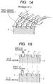
- a recording disk 3 has a surface provided with guide grooves 1 for controlling the position of a recording head, and recording bits 2 formed in the guide grooves 1 for high-density recording.
- Fig. 1A is a perspective view of the recording device, and Figs. 1B are sectional views taken on line a-a' and on line b-b', respectively, in Fig. 1A.
- the guide grooves 1 are U-shaped.
- the recording bits 2 have the shape of a tadpole in a plane.
- the width Ws of the recording bits 2 is greater than the width Wg of the guide grooves 1.
- An AFM probe 6' (Fig.
- the AFM probe 6' can be positioned with respect to a radial direction in an accuracy of 10 nm or below. When a tip part 6 of the AFM probe 6' coincides with the recording bit 2, the tip part 6 drops deep into the guide groove 1 as shown in Fig. 2B, whereby the recording bit 2 is detected.
- a recording device in a second embodiment employs AFM techniques.
- the recording device comprises an AFM head, a disk rotating mechanism and a control system.
- the AFM head is provided with the AFM probe 6' having the tip part 6 and a cantilever arm 7 held at one end thereof, an optical lever detection system for detecting a force exerted on the tip part 6 of the AFM probe 6', a recording piezoelectric device 11, and an XYZ scanner 14 for controlling the tip part 6.
- the optical lever detection system comprises, as basic components, a laser light source 4, and a position detector 5 for detecting a light beam 12.
- the recording device is provided with a rough control mechanism, probe advancing/retracting mechanism and a probe seek mechanism, which are omitted in Fig. 2A for simplicity.
- the disk rotating mechanism comprises a motor 22, ball bearings and a disk table 31.
- the stator 37 of the motor 22 and the inner rings 33 of the ball bearings are fastened to a shaft 38 set on a base 39.
- a rotor has a cylindrical part 35 of iron fixedly fitted in the boss of the table 31.
- the outer rings 32 of the ball bearings and a magnet rotor 36 are mounted on the cylindrical part 35.
- Balls 34 are held between the outer ring 32 and the inner ring 33 of each of the ball bearings.
- the table 31 is able to rotate. Liquid bearings may be employed instead of the ball bearings.
- a liquid bearing can be formed by sealing a liquid between an outer ring and an inner ring respectively corresponding to the outer ring 32 and the inner ring 33 of the ball bearing.
- nonrepeatable radial position error is in the range of 20 to 200 nm. Highly reliable writing and reading operation can be achieved when the recording disk of the present invention is used in combination with the disk rotating mechanism of the present invention.
- the recording disk 3 is supported on the table for writing, reading and erasing operations.
- a controller 20 receives a position signal 15, i.e., information about the position of the tip part 6 of the probe 6', provided by the position detector 5 upon the detection of a light beam 12, and executes a position control operation, a recording signal detecting operation and a write signal generating operation.
- the controller 20 includes a position control unit 16 which receives position information about the position of the tip part 6 of the probe 6', and executes a tracking control operation, and a position control operation for controlling the three-dimensional position of the tip part 6 of the probe 6'.
- the recording disk 3 is a ROM disk (read-only memory disk)
- the recording bits 2 are formed in all the guide grooves 1, and information is read by detecting the vertical movement of the probe 6'.
- the recording disk 3 is a RAM disk (random-access memory disk)
- address information and system information are read through the detection of the probe 6', and information is recorded in data sections in which any recording bits 2 are not formed, information is erased, and information is read by a small magnetic head formed in the probe 6'.
- the recording disk 3 is a WORM disk (write-once read-many disk)
- recording bits are formed in the data section by pressing a probe into the data sections to form the concave bits using nanoindentations. If a near field optical probe is used instead of the probe 6', ROMs, RAMs and WORMs can be realized.
- the probe 6' may be mounted on a slider.
- Fig. 3 is a diagrammatic view of assistance in explaining a tracking control operation when a recording disk provided with guide grooves 1 of a V-shaped cross section is used.
- a laser beam 12 reflected by the back surface of the cantilever arm 7 falls on the position detector 5 having four photodetectors.
- the position detector 5 may be such as provided with photodetectors arranged in a two-dimensional arrangement.
- the output signal of the position detector 5 is positive when the tip part 6 of the probe 6' moves in one direction from the center of the guide groove and is negative when the tip 6 of the probe 6' moves in the opposite direction from the center of the guide groove.
- This characteristic of the output signal of the position detector 5 is substantially linear when the tip part 6 of the probe 6' moves in the guide groove.
- the deviation of the tip part 6 of the probe 6' from the center of the guide groove is determined as the variation of the lateral force, the XYZ scanner 14 is controlled so as to keep the tip part 6 of the probe 6' always on the center of the guide groove.
- the tip part 6 of the probe 6' When the tip part 6 of the probe 6' come to a position corresponding to the recording bit 2, the tip part 6 of the probe 6' sinks further into the recording disk 3, and the depth of sinking of the tip part 6 into the guide groove increases by an increment ⁇ Z as illustrated in Fig. 2B.
- the circuit shown in Fig. 3A generates a contact signal on the basis of the increment ⁇ Z. Vibrational motions of 10 kHz or below of the probe 6' are caused by a strain in the recording disk 3.
- the position control unit 16 controls the XYZ scanner 14 to control the position of the tip part 6 of the probe 6' with respect to a direction parallel to the Z-axis so that the tip part 6 of the probe 6' is in contact with the recording disk 3 at a constant contact pressure.
- the controller 20 decides that vibrations of the probe 6' at frequencies of 1 MHz or above are information signals, and processes the information signals for reading.
- information recorded in an ultrahigh density on the recording disk 3 of the present invention provided with recording tracks arranged at a track pitch of 0.5 ⁇ m or below can be read without causing errors even if a conventional disk rotating mechanism employing ball bearings or liquid bearings is used for rotating the recording disk 3.
- a recording disk 3 in a second embodiment according to the present invention is provided with guide grooves 1 of a substantially V-shaped cross section rather than a U-shaped cross section.
- the guide grooves 1 are formed in such a shape when the same are formed by a conventional process, such as a replica process, an etching process or a lithographic process.
- a recording disk 3 in a third embodiment according to the present invention is provided with guide grooves 1 and recording bits 2 of a depth greater than that of the guide groove 1.
- This recording disk 3 enables the enhancement of signal intensity, which improves the S/N ratio.
- a recording disk in a modification of the recording disk 3 shown in Fig. 4B may be provided with guide grooves and convex recording bits of a depth smaller than that of the guide groove.
- This recording disk can be formed by etching a surface of a disk blank with regions corresponding to the convex recording bits in the surface of the disk blank covered with a resist. The height of the convex recording bits can be detected more surely than the depth of the concave recording bits.
- the tip of the tip part of the probe is unable to reach the bottom of the recording bits.
- the convex recording bits is free from such a problem and hence is capable of improving the S/N ratio.
- a recording disk 3 in a fourth embodiment according to the present invention is provided with guide grooves 1 and recording bits 1 dislocated from the center of the guide grooves 1.
- the recording disk may be formed of any suitable material. In most cases, the recording disk is formed of an organic material, such as a polycarbonate resin.
- the surface of the recording disk may be of a multilayer structure, and the bottom wall of the guide grooves and the side walls of the guide grooves may be formed of other materials, respectively.
- the structure of the recording disk in accordance with the present invention may be applied only to the header (address part) and servo region of each sector on a conventional recording disk. Only guide grooves 1 may be formed in the rest of parts serving as data parts to use the recording disk for ultrahigh-density recording. In such a case, the servo region of a sector needs only a recording bit 2 for a clock. This can be used for write-once erasable recording. For example, when writing data to the grooves 1 of the data region of a polycarobonate recording disk by a force modulation recording method, the recording piezoelectric device 11 shown in Fig. 2 is driven to form recording bits 2 in the guide grooves 1 by applying pulsed force to the recording disk.
- the recording disk may be provided with a coating of a magnetic recording material, a magnetooptic material, a phase-changeable material or an organic dye recording material, and the coating may be covered with a protective film.
- the guide grooves may partly be interrupted.
- the guide grooves may be formed in concentric circles or in a spiral.
- a magnetic head or a head provided with a near field optical probe may be employed instead of the AFM probe.
- ultrahigh-density recording can be achieved with high reliability by a conventional disk rotating mechanism employing ball bearings or liquid bearings and apt to cause nonrepeatable radial positioning error (NRRE: nonrepeatable run-out error) even if the track length or the track pitch of the recording disk is 0.5 ⁇ m or below.
- NRE nonrepeatable radial positioning error
Landscapes
- Magnetic Record Carriers (AREA)
- Moving Of Heads (AREA)
- Adjustment Of The Magnetic Head Position Track Following On Tapes (AREA)
Applications Claiming Priority (2)
| Application Number | Priority Date | Filing Date | Title |
|---|---|---|---|
| JP1536898 | 1998-01-28 | ||
| JP10015368A JPH11213301A (ja) | 1998-01-28 | 1998-01-28 | 記録媒体および記録装置 |
Publications (2)
| Publication Number | Publication Date |
|---|---|
| EP0933771A2 true EP0933771A2 (fr) | 1999-08-04 |
| EP0933771A3 EP0933771A3 (fr) | 2001-02-14 |
Family
ID=11886859
Family Applications (1)
| Application Number | Title | Priority Date | Filing Date |
|---|---|---|---|
| EP99100881A Withdrawn EP0933771A3 (fr) | 1998-01-28 | 1999-01-19 | Milieu et dispositif d'enregistrement |
Country Status (3)
| Country | Link |
|---|---|
| US (2) | US6370107B1 (fr) |
| EP (1) | EP0933771A3 (fr) |
| JP (1) | JPH11213301A (fr) |
Families Citing this family (28)
| Publication number | Priority date | Publication date | Assignee | Title |
|---|---|---|---|---|
| JP3639943B2 (ja) * | 1998-04-22 | 2005-04-20 | 富士通株式会社 | 磁気記録媒体及び磁気ヘッド装置 |
| JP4162292B2 (ja) * | 1998-07-07 | 2008-10-08 | セイコーインスツル株式会社 | 情報記録媒体および情報再生装置 |
| US6665239B1 (en) * | 1998-12-10 | 2003-12-16 | Ricoh Company, Ltd. | Optical information recording and reproducing apparatus |
| US6742380B2 (en) * | 2000-07-28 | 2004-06-01 | Seagate Technology Llc | Technique for measuring small distances between, and for measuring the flatness of, electrically conductive surfaces |
| US6658922B2 (en) * | 2001-02-20 | 2003-12-09 | Seagate Technology Llc | Optical equipment assemblies and techniques indexed to a common spindle |
| US6898037B2 (en) * | 2001-02-20 | 2005-05-24 | Seagate Technology Llc | Optical equipment assemblies and techniques |
| US7305319B2 (en) * | 2001-09-28 | 2007-12-04 | The University Of North Carolina | Methods and systems for three-dimensional motion control and tracking of a mechanically unattached magnetic probe |
| JP4113041B2 (ja) * | 2003-05-14 | 2008-07-02 | 株式会社日立製作所 | 磁化制御方法および情報記録装置 |
| US7315505B2 (en) * | 2003-07-14 | 2008-01-01 | Hewlett-Packard Development Company, L.P. | Storage device having a probe with plural tips |
| US7215633B2 (en) * | 2003-08-13 | 2007-05-08 | Hewlett-Packard Development Company, L.P. | Storage device having a probe with a tip to form a groove in a storage medium |
| US7173314B2 (en) * | 2003-08-13 | 2007-02-06 | Hewlett-Packard Development Company, L.P. | Storage device having a probe and a storage cell with moveable parts |
| US7164646B2 (en) * | 2004-02-19 | 2007-01-16 | Hewlett-Packard Development Company, L.P. | Storage device having a storage cell programmable to one of more than two storage states |
| US7167434B2 (en) * | 2004-03-09 | 2007-01-23 | Hewlett-Packard Development Company, L.P. | Storage device having a probe with a first plate that cooperates with a second plate to provide a variable capacitance |
| US7167435B2 (en) * | 2004-03-09 | 2007-01-23 | Hewlett-Packard Development Company, L.P. | Storage device having a probe with plural tips |
| US7184388B2 (en) | 2004-03-09 | 2007-02-27 | Hewlett-Packard Development Company, L.P. | Heating elements for a storage device |
| US7254108B2 (en) * | 2004-03-15 | 2007-08-07 | Hewlett-Packard Development Company, L.P. | Storage device including a probe having an electrically conductive tip portion for electrical contact with a storage medium |
| US6999403B2 (en) * | 2004-04-02 | 2006-02-14 | Hewlett-Packard Development Company, L.P. | Storage device having a probe to cooperate with a storage medium to provide a variable resistance |
| US7301886B2 (en) * | 2004-05-10 | 2007-11-27 | Hewlett-Packard Development Company, L.P. | Storage device having a read circuit to detect a storage state based on interaction between a probe and a storage medium |
| US7362549B2 (en) * | 2004-05-19 | 2008-04-22 | Seagate Technology Llc | Storage device having first and second magnetic elements that interact magnetically to indicate a storage state |
| US7310298B2 (en) * | 2004-05-20 | 2007-12-18 | Hewlett-Packard Development Company, L.P. | Storage device having a probe to form structures for representing data states |
| KR100580651B1 (ko) * | 2004-06-03 | 2006-05-16 | 삼성전자주식회사 | 프로브를 이용한 정보저장시스템의 위치오차 검출 장치 및방법, 이를 이용한 정보저장시스템의 정보 추종 장치 및방법 |
| WO2006020187A2 (fr) * | 2004-07-16 | 2006-02-23 | The University Of North Carolina At Chapel Hill | Procedes, systemes et progiciels de projection en spectre continu |
| US7236446B2 (en) * | 2004-07-23 | 2007-06-26 | Hewlett-Packard Development Company, L.P. | Compensating for variations in the temperature of a probe of a storage device |
| KR100612857B1 (ko) * | 2004-08-14 | 2006-08-14 | 삼성전자주식회사 | 프로브를 이용한 정보저장시스템의 프로브 위치오차 검출방법 및 장치 |
| US8490469B2 (en) * | 2007-02-22 | 2013-07-23 | The University Of North Carolina | Methods and systems for multiforce high throughput screening |
| ES2823456T3 (es) | 2009-06-25 | 2021-05-07 | Univ North Carolina Chapel Hill | Método y sistema para utilizar postes unidos a una superficie accionados para evaluar la reología de fluidos biológicos |
| EP2926115B1 (fr) | 2012-11-30 | 2021-05-26 | The University of North Carolina At Chapel Hill | Procédés et systèmes permettant de déterminer les propriétés physiques d'un échantillon dans un dispositif de diagnostic portable utilisé au chevet du patient |
| US9406009B2 (en) * | 2012-12-14 | 2016-08-02 | International Business Machines Corporation | Method and apparatus to tag metal |
Family Cites Families (19)
| Publication number | Priority date | Publication date | Assignee | Title |
|---|---|---|---|---|
| DE2449136A1 (de) * | 1973-03-27 | 1975-10-16 | Ted Bildplatten | Verfahren zur herstellung eines signaltraegers mit spurfuehrung und nach dem verfahren hergestellter signaltraeger |
| US4027330A (en) * | 1973-03-27 | 1977-05-31 | Ted-Bildplatten Aktiengesellschaft, Aeg-Telefunken, Teldec | Disc recording |
| NL8802335A (nl) * | 1988-09-21 | 1990-04-17 | Philips Nv | Werkwijze en inrichting voor het op sub-mikron schaal bewerken van een materiaal-oppervlak. |
| JPH02187944A (ja) * | 1989-01-13 | 1990-07-24 | Sharp Corp | 再生装置 |
| JP2859715B2 (ja) * | 1989-08-10 | 1999-02-24 | キヤノン株式会社 | 記録媒体用基板及びその製造方法、記録媒体、記録方法、記録再生方法、記録装置、記録再生装置 |
| US5255259A (en) * | 1990-04-18 | 1993-10-19 | Canon Kabushiki Kaisha | Method of access to recording medium, and apparatus and method for processing information |
| US5537372A (en) * | 1991-11-15 | 1996-07-16 | International Business Machines Corporation | High density data storage system with topographic contact sensor |
| DE69309318T2 (de) | 1992-01-10 | 1997-10-30 | Hitachi, Ltd., Tokio/Tokyo | Verfahren und Vorrichtung zum Beobachten einer Fläche |
| US5481530A (en) * | 1992-10-20 | 1996-01-02 | Mitsubishi Chemical Corporation | High density optical recording method and recording medium |
| JPH09128827A (ja) * | 1995-08-29 | 1997-05-16 | Sony Corp | 光磁気記録媒体、記録方法及び光磁気記録装置 |
| JPH09134552A (ja) * | 1995-09-06 | 1997-05-20 | Hitachi Ltd | トラッキング方法と記憶装置 |
| KR970017286A (ko) * | 1995-09-06 | 1997-04-30 | 가나이 츠토무 | 트랙킹방법과 기억장치 |
| JPH09259440A (ja) * | 1996-03-25 | 1997-10-03 | Sony Corp | 記録媒体、アドレス記録方法および装置、並びに、記録再生方法および装置 |
| JP3476647B2 (ja) * | 1996-04-19 | 2003-12-10 | シャープ株式会社 | 光ディスク、光ディスク製造装置および光ディスク記録再生装置 |
| US6243350B1 (en) * | 1996-05-01 | 2001-06-05 | Terastor Corporation | Optical storage systems with flying optical heads for near-field recording and reading |
| JP2856390B2 (ja) * | 1996-07-26 | 1999-02-10 | 株式会社日立製作所 | 情報記録媒体及びそれを用いた記録再生方法 |
| JPH1092016A (ja) * | 1996-09-12 | 1998-04-10 | Nikon Corp | 光ディスク |
| US5822285A (en) * | 1997-03-31 | 1998-10-13 | International Business Machines Corporation | Atomic force microscopy disk data storage system with nonradial tracking lines |
| US5856967A (en) * | 1997-08-27 | 1999-01-05 | International Business Machines Corporation | Atomic force microscopy data storage system with tracking servo from lateral force-sensing cantilever |
-
1998
- 1998-01-28 JP JP10015368A patent/JPH11213301A/ja active Pending
-
1999
- 1999-01-19 EP EP99100881A patent/EP0933771A3/fr not_active Withdrawn
- 1999-01-26 US US09/237,240 patent/US6370107B1/en not_active Expired - Fee Related
-
2001
- 2001-07-26 US US09/912,353 patent/US20010040864A1/en not_active Abandoned
Also Published As
| Publication number | Publication date |
|---|---|
| US20010040864A1 (en) | 2001-11-15 |
| US6370107B1 (en) | 2002-04-09 |
| EP0933771A3 (fr) | 2001-02-14 |
| JPH11213301A (ja) | 1999-08-06 |
Similar Documents
| Publication | Publication Date | Title |
|---|---|---|
| US6370107B1 (en) | Recording medium and recording device | |
| US5808977A (en) | Tracking method and recording means thereby | |
| US6545970B2 (en) | Near field magneto-optical head having read and write pinhole apertures | |
| CN101393755B (zh) | 光信息再生方法、光信息再生装置以及光信息记录介质 | |
| EP0306324B1 (fr) | Système de mémorisation optique | |
| EP0336616B1 (fr) | Disque optique compatible | |
| JP3230376B2 (ja) | 光学的情報記憶装置 | |
| EP1467358B1 (fr) | Support d'enregistrement, dispositif d'enregistrement d'informations et dispositif de reproduction d'informations | |
| WO2001065547A1 (fr) | Procede et dispositif d'enregistrement/lecture d'informations et support d'enregistrement d'informations | |
| US6487165B1 (en) | Optical recording medium | |
| JPH1116101A (ja) | 情報再生装置、情報記録装置、および、情報記録媒体 | |
| KR100440807B1 (ko) | 하드 디스크 드라이브에서의 클럭신호 기록, 독출 장치 및방법과 그를 위한 구조의 디스크 | |
| JPH0917032A (ja) | 光情報記録媒体 | |
| JPH09251667A (ja) | ディスク | |
| JPH11154363A (ja) | 情報記録媒体および情報検出装置 | |
| US20070076087A1 (en) | Optical disc apparatus | |
| JP2000357324A (ja) | 光記録媒体に対する情報記録及び(又は)再生方法並びに光記録媒体 | |
| JPS62262281A (ja) | 回転記録媒体円盤の記録再生装置 | |
| JP2002175627A (ja) | 光記録媒体用スタンパの作製方法およびそのスタンパを使用して作製した光記録媒体 | |
| JP2003045099A (ja) | ディスク再生および検査装置 | |
| JPH0850730A (ja) | 光ディスクの溝信号振幅評価装置と記録再生装置 | |
| JP2002025070A (ja) | 表面再生型光記録媒体 | |
| JPH10214419A (ja) | 磁気記録媒体および磁気記録装置 | |
| JP2002025071A (ja) | 表面再生型光記録媒体 | |
| JPS63155424A (ja) | 光デイスクの情報書換え方法 |
Legal Events
| Date | Code | Title | Description |
|---|---|---|---|
| PUAI | Public reference made under article 153(3) epc to a published international application that has entered the european phase |
Free format text: ORIGINAL CODE: 0009012 |
|
| AK | Designated contracting states |
Kind code of ref document: A2 Designated state(s): DE FR GB |
|
| AX | Request for extension of the european patent |
Free format text: AL;LT;LV;MK;RO;SI |
|
| PUAL | Search report despatched |
Free format text: ORIGINAL CODE: 0009013 |
|
| AK | Designated contracting states |
Kind code of ref document: A3 Designated state(s): AT BE CH CY DE DK ES FI FR GB GR IE IT LI LU MC NL PT SE |
|
| AX | Request for extension of the european patent |
Free format text: AL;LT;LV;MK;RO;SI |
|
| 17P | Request for examination filed |
Effective date: 20010223 |
|
| AKX | Designation fees paid |
Free format text: DE FR GB |
|
| STAA | Information on the status of an ep patent application or granted ep patent |
Free format text: STATUS: THE APPLICATION HAS BEEN WITHDRAWN |
|
| 18W | Application withdrawn |
Withdrawal date: 20021108 |