EP0933924A2 - Bildverarbeitungsvorrichtung - Google Patents
Bildverarbeitungsvorrichtung Download PDFInfo
- Publication number
- EP0933924A2 EP0933924A2 EP99300595A EP99300595A EP0933924A2 EP 0933924 A2 EP0933924 A2 EP 0933924A2 EP 99300595 A EP99300595 A EP 99300595A EP 99300595 A EP99300595 A EP 99300595A EP 0933924 A2 EP0933924 A2 EP 0933924A2
- Authority
- EP
- European Patent Office
- Prior art keywords
- image
- brightness
- mask
- data
- processing
- Prior art date
- Legal status (The legal status is an assumption and is not a legal conclusion. Google has not performed a legal analysis and makes no representation as to the accuracy of the status listed.)
- Granted
Links
- 238000012545 processing Methods 0.000 title claims abstract description 185
- 238000000034 method Methods 0.000 claims abstract description 84
- 238000012937 correction Methods 0.000 claims abstract description 73
- 230000008569 process Effects 0.000 description 37
- 239000003086 colorant Substances 0.000 description 35
- 238000004364 calculation method Methods 0.000 description 21
- 238000003672 processing method Methods 0.000 description 16
- 230000002349 favourable effect Effects 0.000 description 13
- 230000000694 effects Effects 0.000 description 9
- 230000006870 function Effects 0.000 description 9
- 230000009467 reduction Effects 0.000 description 8
- 230000002087 whitening effect Effects 0.000 description 7
- 230000002542 deteriorative effect Effects 0.000 description 6
- 238000010586 diagram Methods 0.000 description 5
- 238000002834 transmittance Methods 0.000 description 5
- 101100095796 Caenorhabditis elegans sig-7 gene Proteins 0.000 description 3
- 238000012935 Averaging Methods 0.000 description 2
- 230000008901 benefit Effects 0.000 description 2
- 238000001514 detection method Methods 0.000 description 2
- 238000003708 edge detection Methods 0.000 description 2
- 230000005540 biological transmission Effects 0.000 description 1
- 230000008859 change Effects 0.000 description 1
- 238000001914 filtration Methods 0.000 description 1
- 238000002156 mixing Methods 0.000 description 1
- 230000004048 modification Effects 0.000 description 1
- 238000012986 modification Methods 0.000 description 1
- 230000007480 spreading Effects 0.000 description 1
Images





Classifications
-
- H—ELECTRICITY
- H04—ELECTRIC COMMUNICATION TECHNIQUE
- H04N—PICTORIAL COMMUNICATION, e.g. TELEVISION
- H04N1/00—Scanning, transmission or reproduction of documents or the like, e.g. facsimile transmission; Details thereof
- H04N1/40—Picture signal circuits
- H04N1/407—Control or modification of tonal gradation or of extreme levels, e.g. background level
- H04N1/4072—Control or modification of tonal gradation or of extreme levels, e.g. background level dependent on the contents of the original
- H04N1/4074—Control or modification of tonal gradation or of extreme levels, e.g. background level dependent on the contents of the original using histograms
Definitions
- This invention relates to an image processing method and image processing apparatus capable of dodging or shutting light method, and in particular, to an image processing method and image processing apparatus capable of electronically making the image processing for dodging for the image data read by an image reading means.
- a technique called 'dodging' or 'burning-in' is sometimes used.
- the above-mentioned dodging and burning-in (hereinafter referred to as 'dodging' inclusively in this specification) are the methods for obtaining a print without saturation in the light and dark portions, keeping a good contrast and gradation of each photographic object, by giving long time exposure selectively for the area considered to become uniformly white by using a shielding plate with a hole and giving short time exposure selectively for the area considered to become black fill-in by using a shielding plate, while giving usual exposure for the area of intermediate density. Further, in case of printing from a positive-film, a print without saturation can be obtained by the reversed operation of the above.
- soft focusing is practiced.
- in order to obtain a soft focus image with an appearance of blurred light as obtained by using a soft filter at the time of photographing it is required to superpose a mask image with respect to respective numerical values corresponding to the brightness (energy quantity E) at the time of photographing.
- a soft focus processing to be made at the time of printing can also be available; it is characterized by obtaining a print of a spread color, and in low key. In this case too, it can not be actualized by merely blending the image data values corresponding to density or L*, but it requires the calculation process such as converting density or L* into print exposure quantity E' ⁇ composing processing ⁇ converting E' into density or L*, resulting in a heavy load like the soft focus processing of the type made at the time of photographing.
- an object of this invention to actualize an image processing method and an image processing apparatus capable of practicing an image processing for dodging getting rid of the saturation at the light portions and at the dark potions with the contrast and gradation reproduction of each photographic object kept good.
- An image processing method comprises the steps of:
- An image processing apparatus comprises:
- An image processing apparatus for carrying out dodging image processing comprising:
- 'data concerning the brightness' means, in addition to the brightness, various pieces of information concerning the lightness of the photographic object such as the transmission (reflection) density of the original, the print exposure quantity E, logE, and the transmittance (reflectance) of the original.
- the set' means the peak of the histogram, the set as the positions of the image or the like.
- 'a mask' means data composed of the data of a pixel group having the same size as the image, being the one for being subjected to various kinds of processes with the data of the corresponding pixels of the original image.
- the original image data are divided into a plurality of groups or blocks on the basis of the data concerning the brightness of the original image. Then, a dodging mask for adding it to the image data of at least one of these plural blocks or groups, a correction value different to those added to the other blocks or groups, is prepared. Further, regarding the dividing of the data into a plurality of blocks or groups, a dividing process is carried out in accordance with the frequencies of emergence or with the manner of the arrangements at the respective image positions of the data concerning the brightness of the original image.
- image processing such as adding calculation is carried out for the respective pixels of this mask and those of the original image corresponding to them; hence, it is actualized the image processing for dodging to get rid of saturation at the light portions and dark portions, with the contrast and gradation reproduction of each of the photographic objects kept good.
- the image processing is such a processing as to add the data of the original image to the data of the mask for each of the corresponding pixels.
- the data is divided into a plurality of groups on the basis of the histogram of the data concerning the brightness; it is also favorable that the data is divided into a plurality of groups on the basis of the shape of the histogram.
- the mask is the one for dodging for adding it to the data of at least one of the plural groups a correction value different to those added to the other groups.
- An image processing apparatus set forth in the paragraph (1) wherein the data concerning the brightness are obtained out of the thinned data of the original image, and the aforesaid image processing means enlarges the dodging mask prepared according to the set of frequencies of emergence of these data concerning the brightness to the same size as the original image after it is blurred by a blurring filter, and carries out the adding operation with the pixels of this dodging mask and those of the original image corresponding to them.
- the process blurring the dodging mask is carried out a plurality of times to prepare it, hence, a dodging mask having a smooth shape can be prepared and a natural dodging can be actualized.
- An image processing apparatus set forth in any one of the paragraphs (1) - (3), wherein the aforesaid original image to be read is a color image, and the aforesaid image processing means obtains the data concerning the brightness included in the color image to prepare the dodging mask, which is added to the plural color components of the original image.
- the data concerning the brightness are obtained to prepare the dodging mask. Further, dodging is actualized by adding this dodging mask (the same mask for the respective color components) to the respective plural color components of the original image.
- the density values of the respective color components of a negative color image are read, and the data concerning the brightness (monochromatic data) are obtained from the average values of these density values of the respective color components to prepare the dodging mask. Further, dodging is actualized by adding this dodging mask (the same mask for the respective color components) to the respective plural color components of the original image.
- An image processing apparatus set forth in any one of the paragraphs (1) - (5), wherein the aforesaid image processing means obtains a plurality of different correction values from the aforesaid plural blocks, prepares the dodging mask from this correction values, and carries out an adding operation with this dodging mask and the corresponding pixels of the original image.
- the dodging mask is prepared according to the data sets in the histogram; hence, it is actualized an image processing for dodging to get rid of saturation in the light and dark portions, with the contrast and gradation reproduction of each of the photographic objects, from the shadow area to the highlight area, kept good.
- An image processing method comprising the steps of:
- An image processing apparatus wherein the aforesaid image processing means obtains the image data for the respective color components included in the image in a condition that the original image is thinned to produce images for the respective colors, enlarges said produced images for the respective colors to the same image size as the original image after blurring them by a blurring filter to produce blurred images for the respective colors, and carries out a weighted adding operation with this blurred images for the respective colors and the corresponding pixels of the respective color components of the original image to produce a soft focus image.
- color images for the respective color components are blurred, enlarged, and subjected to a weighted adding operation to the original image in a manner such that the total sum of the addition becomes one (1); hence, soft focus processing of the type made at the time of photographing or of the type made at the time of printing can be actualized without deteriorating the color tone in soft focus processing.
- An image processing method comprising the steps of:
- An image processing apparatus for carrying out soft focus processing comprising image processing means for carrying out soft focus processing
- color images for the respective color components are blurred and enlarged, and a predetermined calculation process is executed to the remainder of the subtraction of this blurred images for the respective colors by the corresponding pixels of the respective color components of the original image, and further, the data values of the corresponding pixels of the respective color components of the original image are added to the result; hence, soft focus processing of the type made at the time of photographing or of the type made at the time of printing can be actualized without deteriorating the color tone in soft focus processing.
- images for the respective colors are produced from the color image in a condition that the original image is thinned, and are blurred, the amount of processing can be reduced.
- the image processing apparatus as an apparatus carrying out the image processing method of an example of the embodiment of this invention will be explained with reference to the block diagram in Fig. 1.
- the scanner 100 is the scanner as the image reading means, which reads the desired image from a light transmitting original such as a photographic film or a light reflecting original such as a printed matter and outputs it as digital data.
- a light transmitting original such as a photographic film or a light reflecting original such as a printed matter
- 200 is the image processing apparatus, the main part of this invention, and is provided with all the processing means to be described later.
- 300 is the printer as the image outputting means, which prints the image processed by the image processing apparatus 200.
- the 400 is the display control portion, which carries out the display control of the image processed in the image processing apparatus 200 (generation of the image to be displayed).
- the display means such as a CRT display portion, which displays the image generated in the display control portion 400. Further, in this CRT display portion 500, it is possible to confirm the image to be printed by displaying it beforehand.
- the density value LUT which is an LUT for converting the digital data from the scanner 100 into the data of negative-density data values.
- the reduction processing portion 210 is the reduction processing portion, which is the processing means for reducing the image obtained by the pre-scan to an image having a predetermined size.
- the brightness information generating portion which is the processing means for generating the image having brightness information by making an average of the plural colors R, G, B or Y, M, C or the like.
- the histogram making portion which is the processing means for making a histogram of the brightness values for the data of the image having the brightness information.
- the judgment process portion 240 is the judgment process portion, which divides the sets of the emergence frequencies of these data concerning the brightness into a plurality of blocks at need, by the image judging process to be described later, and determines the correction values in accordance with at least one of these plural blocks.
- the original mask preparing portion which is the processing means for preparing the original mask corresponding to the image, which is the base of the dodging mask, in accordance with the blocks divided by the aforesaid judgment processing.
- the blurring filter processing portion which is the processing means for giving said original mask such amount of blur as to be required in the dodging mask processing by executing the blurring process to said original mask by a blurring filter.
- enlargement processing portion which is the processing means for producing the dodging mask by enlarging the original blurring mask to the size having the same number of pixels as the properly scanned image.
- interpolation of pixels is also done at the time of enlargement processing.
- various kinds of the methods for example, bilinear (linear interpolation) method, cubic convolution method, etc. are known, but any other method may be appropriate if it is the one capable of smooth interpolation processing.
- 280 is the combining portion, which is the processing means for combining the respective corresponding pixels of the proper-scan image and the dodging mask by an adding operation.
- Fig. 2 is a flow chart showing the steps of the procedure of the processing of the image data practiced by the image processing apparatus 200. In the following, the explanation will be given in accordance with the steps of the procedure of the processing shown in Fig. 2.
- FIG. 3 is an illustration schematically showing the data produced and prepared with the processing
- Fig. 4 shows an example of an original image and its contents as well as the histogram produced from the original image.
- figures on and after Fig. 5 are illustrations for explaining the respective processing.
- a negative-film with an original image recorded on it or the like is set on the scanner 100 to practice a pre-scan (S1 in Fig. 2).
- This pre-scan is the process for displaying the image to be printed previously before printing, and further by this display, for judging the necessity of the dodging processing and confirming the result; hence, the number of the pixels to be read may be small.
- the pre-scan should be of 256 x 384 pixels. Further, this pre-scan gives the data of 256 x 384 pixels x 3 colors by being practiced for the three colors R, G, B simultaneously or sequentially ((2) in Fig. 3).
- the data obtained by this pre-scan are converted into the data of negative-density values by the density value LUT 201.
- these data are reduction-processed by the reduction processing portion 210, and a reduced pre-scan image having a size suitable for the dodging processing ((3) in Fig. 3) is produced (S2 in Fig. 2).
- This reduced pre-scan image should be of 64 x 96 pixels x 3 colors, or of 128 x 192 pixels x 3 colors. It is favorable to carry out the reduction processing by simply averaging the data of neighboring four to sixteen pixels, because the effect of reduction of noises can be obtained.
- the image for the brightness information is produced (S3 in Fig. 2), by making the reduced pre-scan image, which is a color image, a black-and-white image in the brightness information generating portion.
- the reduced pre-scan image which is a color image, a black-and-white image in the brightness information generating portion.
- a monochromatic image for the brightness information having 64 x 96 pixels is obtained ((4) in Fig. 3).
- a histogram of the frequencies of emergence vs. brightness is prepared (S4 in Fig. 2), on condition that the original image is such one as is shown in Fig. 4(a) in this case. Further, the contents of the image are shown in Fig. 4(b) because the detailed color tone and gradation can not be shown in Fig. 4(a).
- the sky, a sea, green objects, a person, a pool, a handrail, the ground, etc. are included.
- the judgment process portion 240 executes the image judging process, and divides the sets of emergence frequencies of the data concerning the brightness into a plurality of blocks (S5 in Fig. 2). In this case, the data are divided into two or more blocks by setting a threshold value using the discrimination criterion method or the like.
- the dodging process is judged to be not necessary, and if they are out of the above-mentioned range M, the processing is continued; however, in the case where the image is displayed on the CRT display portion 500 and the operator instructs the dodging processing, a definite amount of dodging processing may be done regardless of the value of M.
- the dividing process is done by obtaining a threshold value of the data concerning the brightness through applying the discrimination criterion method to the histogram; however in addition to this, as the method for obtaining the threshold value, the one such that the threshold value is obtained from the shape of the peaks and dips of the histogram or from the shape and the inflection point of the accumulated density function is to be cited.
- the method dividing the original image into a plurality of blocks by using the techniques such as the edge detection in the image field, the domain detection, and the pattern matching; and the one first dividing the original image roughly into a plurality of blocks by obtaining the threshold values of the brightness from said shape of the histogram or the accumulated density function, and next finely defining the domain borders by using the techniques such as said edge detection in the image field, domain detection, and pattern matching.
- the histogram of the brightness is the one as shown in Fig. 6(a)
- several peaks and the dips between them are detected from the shape of the histogram.
- a dip bordering the highlight side to the shadow side is searched to be found, and this dip portion is made a dividing point (Fig. 6(b)).
- the correction value by the dodging mask should be obtained in the judgment process portion 240, in order that the maximum density and the minimum density may be included in the predetermined range M.
- the dodging mask shall be prepared in accordance with at least one of the plural blocks (S6 in Fig. 2).
- the original mask preparing portion 250 produces the image, which is binarized by making the brightness of this dividing point the threshold value, from the image for the brightness information (Fig. 5(c)). Further, the original mask is produced by reversing this binarized image (S6 in Fig. 2, (5) in Fig. 3, Fig. 5(d)). In this case, the data of 64 x 96 pixels x 1 (color), the same as the image for the brightness, can be obtained.
- the blurring filter processing portion 260 executes the blurring filter processing of the order 3 x 3 - 5 x 5 to the original mask (S7 in Fig. 2).
- the blur processing is to be repeated plural number n times so that the mask may have a suitable amount of blur for dodging (S8 in Fig. 2).
- the enlargement processing portion 270 executes the enlargement processing to the original mask which is given a suitable amount of blur to prepare the dodging mask enlarged to the same size (1024 (vertical) x 1536 (horizontal) pixels) as the proper-scan image obtained by the proper scan (S9 in Fig. 2, (6) in Fig. 3).
- the mask prepared by blur-processing and enlarging the original mask as described in the above.
- the proper scan is carried out to obtain the proper-scan image (S10 in Fig. 2, (7) in Fig. 3).
- This proper-scan image have the data of 1024 (vertical) x 1536 (horizontal) pixels x 3 colors.
- the proper-scan image is combined with the dodging mask (S11 in Fig. 2) to obtain the dodged output image ((8) in Fig. 3).
- the same dodging mask is combined with the data for the respective colors of the proper-scan image.
- this word 'combining' means doing adding operation with the respective data of the corresponding pixels of the dodging mask and the original image.
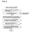
- scene discrimination before processing is carried out with reference to the histogram (S1 in Fig. 8).
- This scene discrimination before processing is a process judging if the dodging process is necessary or not; that is, by comparing the predetermined density range M with the density range N to be obtained from this histogram, the judgment is done in a manner such that the dodging process is necessary or not according as M ⁇ N or M ⁇ N.
- N it is obtained by defining the maximum density as the point of X% from the top of the histogram, and the minimum density as the point of X% from the bottom of the histogram, where X is determined beforehand as any one of the values 0 - 5.
- M ⁇ N and accordingly the dodging process is necessary (S2 in Fig. 8).
- the histogram is divided into two blocks (the block in the highlight side and the block in the shadow side) by the threshold value Th0 (S3 in Fig. 8).
- the discrimination criterion method is a technique to determine the threshold value at the time of dividing into two the histogram used in making the image binarized or in other process. That is, at the time of dividing one histogram into two, the method determines the threshold value to make each of the histograms of the divided blocks arranged to be the smallest in a manner such that the covariance of the divided two groups becomes the smallest.
- the block in the shadow side is further divided into two blocks by the threshold value Th1.
- the block in the highlight side is further divided into two blocks by the threshold value Th2 (S4 in Fig. 8).
- the histogram is divided into four blocks by the three threshold values.
- the peaks and dips of the histogram are detected after it is smoothed by a suitable filter, and the threshold values may be determined successively from the largest one among the larger ones out of them.
- the threshold value Th0 is effective.
- the threshold value Th1 is effective. (av5 - av4)/(sig4 + sig5) > C1, (sig6 + sig5)/sig2 ⁇ C2, and wt2 ⁇ C3.
- the threshold value Th2 is effective. (av7 - av6)/(sig6 + sig7) > C1, (sig6 +sig7)/sig3 ⁇ C2, and wt3 ⁇ C3.
- the explanation will be given on condition that the Th0 and Thl are effective, and Th2 is ineffective. For this reason, as shown in Fig. 10, the following processing for calculating the correction values are to be continued, setting that the 'range 1' is from the minimum value to Th1, the 'range 2' is from Th1 to Th0, and the 'range 3 is from Th0 to the maximum value.
- the density range to be obtained from the histogram may be included in the predetermined density range M.
- this maximum correction value L it is possible to set that it has a constant rate (0.1 - 0.5) for the designated scene.
- correction values of the respective ranges to the image data belonging to the respective ranges, it is possible to make the range of the brightness to be nearly included in the desired range.
- the correction values are used as the blurred mask, it is possible that, microscopically viewing, some parts that are not included in the range are present; however, no problem will never occur in practical use.
- the correction values for the respective ranges J1 - J3 are restricted in the following ranges:
- the resultant value of the correction for the lowest density belonging to the range 2 is made a smaller value than the resultant value of the correction for the lowest density (minimum density) belonging to the range 1, the darker block to make the image lacking in natural tone as a photograph.
- the histogram is present in the range 1 - range 3 as shown in Fig. 11(a), it appears the state where nearly no data are present in the neighborhood of the threshold value Th1.
- the amount of data which makes the gradation completely reversed should not be more than 10% of the amount of the data in the range which includes less image data than the other of the relating ranges (the range 1 and the range 2 in this case).
- the following additional correction value j which varies in accordance with the image density data value, is defined and can be used by being added to the correction values J of the respective ranges determined to be within the possible ranges, because sufficient corrections can not be made by only the correction values defined by the above-mentioned inequalities.
- the final correction value C is obtained by the following equation corresponding to each density value x:
- C[x] (additional correction value j[x] corresponding to x) + (the correction value J[class] of the range to which x belongs), where, the class is any one of 1 - 3.
- the correction value C[x] when the correction value C[x] is obtained in the above-mentioned manner, it is desirable that the amount of blur at the time of blurring the original mask should be varied in accordance with the correction value. That is, it is favorable from the view point that more natural result of correction can be obtained, to cope with the variation of the correction value by changing the size of the blurring filter and the number of times of filtering in accordance with the correction value.
- the correction value is obtained on the basis of the average value of the image information of a whole image field; hence, the dodging process can be actualized without the need to add any modification to the other various kinds of image processing algorithm such as density- and color- correction required in photographic printing.
- the practical dodging process is a simple one only adding the correction values to the original image, the processing for the scene which does not need the dodging process may be done by merely deleting the adding instruction only, or skipping it; therefore, the method has also an advantage that the selection to use or not to use the function is possible without giving any influence to the other necessary image processing algorithms.
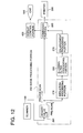
- the block diagram in Fig. 12 is the image processing apparatus 200' provided with the circuit block necessary for the soft focus processing, and to the parts that perform the same function as those explained already in the dodging processing, the same numbers are assigned as them.
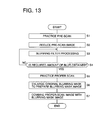
- a negative-film or the like having an original image recorded on it is set on the scanner 100, and the pre-scan process is carried out (S1 in Fig. 13).
- This pre-scan is the process for displaying the image to be printed previously before printing, and further, for confirming by this display the result of the soft focus processing; hence, the number of the pixels to be read may be small.
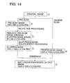
- the pre-scan should be of about 256 x 384 pixels. Further, this pre-scan gives the data of 256 x 384 pixels x 3 colors by being practiced for the three colors R, G, B simultaneously or sequentially ((2) in Fig. 14).
- the data obtained by this pre-scan are converted into the data of negative-density values by the density value LUT 201.
- these data are reduction-processed by the reduction processing portion 210, and a reduced pre-scan image having a size suitable for the soft focus processing ((3) in Fig. 14) is produced (S2 in Fig. 13). Furthermore, this reduced pre-scan image is used as the original blurring mask image.
- This reduced pre-scan image should be of 64 x 96 pixels x 3 colors, or of 128 x 192 pixels x 3 colors. It is favorable to carry out the reduction processing by simply averaging the data of neighboring four to sixteen pixels, because the effect of reduction of noises can be obtained.
- the blurring filter processing portion 260 executes the blurring filter processing of the order 3 x 3 - 5 x 5 to the blurred original mask (S3 in Fig. 13).
- the blur processing may be repeated plural number n times so that the mask may be the one to have a suitable amount of blur as a blurring mask (S4 in Fig. 13).
- This proper-scan image have the data of 1024 (vertical) x 1536 (horizontal) pixels x 3 colors.
- the enlargement processing portion 270 executes the enlargement processing to the original blurring mask which is given a suitable amount of blur to prepare the blurring mask enlarged to the same size (1024 (vertical) x 1536 (horizontal) pixels) as the proper-scan image obtained by the proper scan (S6 in Fig. 13, (5) in Fig. 14).
- the proper-scan image is combined with the blurring mask (S7 in Fig. 13) to obtain the soft-focus-processed output image ((6) in Fig. 14).
- the blurring mask of the corresponding color is combined with the data for each of the colors of the proper-scan image.
- this word 'combining' means doing adding operation with the respective data of the corresponding pixels of the blurring mask and the original image.
- color images for the respective colors are blurred, enlarged, and combined with the original image; hence, soft focus processing can be made without deteriorating the color tone.
- the soft focus processing can be performed; further, it is favorable to carry out the following process, at the time of combining in the combining portion 280:
- the above-described soft focus processing in the third example of the embodiment requires a large amount of memory capacity and calculation processing in order to secure the high precision of the calculation; however, by using the following LUT for soft focus processing, an approximate processing can be carried out simply.
- Fig. 15 is a flow chart showing the outline of the soft focus processing in the fourth example of the embodiment.
- dx 1.0 + 10 (x/100)
- LUT[x] ⁇ log 10 (dx) ⁇ x 100 - 30
- the data obtained by this pre-scan are converted into the data of density values by the density value LUT 201.
- these data are reduction-processed in the reduction processing portion 210 to produce the reduced pre-scan image (S3 in Fig. 15).
- this reduced pre-scan image is used as the original blurring mask image.
- the blurring filter processing portion 260 executes the blurring filter processing of the order 3 x3 - 5 x 5 to the original blurring mask (S4 in Fig. 15).
- the proper scan is practiced to obtain the proper-scan image (S6 in Fig. 15).
- the enlargement processing portion 270 executes the enlargement processing to the original blurring mask which is given a suitable amount of blur to prepare the blurring mask enlarged to the same size as the proper-scan image obtained by the proper scan (S6 in Fig. 15, (5) in Fig. 14).
- the combining portion 280 the proper-scan image is combined with the blurring mask (S7 in Fig. 15) to obtain the soft-focus-processed output image.
- Ti LUT'[Qi - Pi] + Pi.
- the effect of soft focus at the time of photographing can be actualized by only the adding and subtracting operation between the respective image data and by referring to the soft focus processing LUT (the above-mentioned LUT'). Owing to this, it becomes possible to make the amount of calculation reduced and the processing time shortened.
- the soft focus processing at the time of printing can be practiced by the same technique as that used for the one at the time of photographing.
- dx 1.0 + 10 (- ⁇ /100)
- dx 1.0 + 10 (-x/100)
- LUT[x] ⁇ log 10 (dx) ⁇ x 100 - 30
- the soft focus processing is a simple one only adding the LUT'[Qi - Pi] to the proper-scan image Pi; hence, the processing for the scenes which requires no soft focus processing may be practiced merely by deleting the addition instruction only or skipping it, and the method has also the advantage that the selection to use the function or not can be made without giving any influence to the other necessary image processing algorithms.
- the processing in the image processing section 200 or 200' in the above four examples may be conducted by a hardware or a software.
- a program is read out from a medium in which the programs capable of conducting steps indicated in the flowchart of each example are memorized and then the image processing section 200 or 200' conducts the processing in accordance with the program.
Landscapes
- Engineering & Computer Science (AREA)
- Multimedia (AREA)
- Signal Processing (AREA)
- Facsimile Image Signal Circuits (AREA)
- Image Processing (AREA)
Applications Claiming Priority (2)
| Application Number | Priority Date | Filing Date | Title |
|---|---|---|---|
| JP1564098 | 1998-01-28 | ||
| JP1564098 | 1998-01-28 |
Publications (3)
| Publication Number | Publication Date |
|---|---|
| EP0933924A2 true EP0933924A2 (de) | 1999-08-04 |
| EP0933924A3 EP0933924A3 (de) | 2001-08-22 |
| EP0933924B1 EP0933924B1 (de) | 2004-03-24 |
Family
ID=11894327
Family Applications (1)
| Application Number | Title | Priority Date | Filing Date |
|---|---|---|---|
| EP99300595A Expired - Lifetime EP0933924B1 (de) | 1998-01-28 | 1999-01-27 | Bildverarbeitungsvorrichtung |
Country Status (3)
| Country | Link |
|---|---|
| US (1) | US6198844B1 (de) |
| EP (1) | EP0933924B1 (de) |
| DE (1) | DE69915721D1 (de) |
Cited By (8)
| Publication number | Priority date | Publication date | Assignee | Title |
|---|---|---|---|---|
| EP1231564A1 (de) * | 2001-02-09 | 2002-08-14 | GRETAG IMAGING Trading AG | Digitale lokale Bildeigenschaftssteuerung mittels Masken |
| EP1231566A1 (de) * | 2001-02-09 | 2002-08-14 | GRETAG IMAGING Trading AG | Digitale lokale Bildeigenschaftssteuerung mittels Masken |
| EP1093295A3 (de) * | 1999-10-15 | 2003-11-26 | Riso Kagaku Corporation | Bildverarbeitungsvorrichtung und -verfahren |
| DE10233320A1 (de) * | 2002-07-22 | 2004-03-04 | Hans Strasburger | Verfahren und Vorrichtung zur Leuchtdichte-richtigen Darstellung eines Bildes |
| EP1376469A3 (de) * | 2002-06-27 | 2005-01-26 | Noritsu Koki Co., Ltd. | Methode und System zur Erzeugung eines Weichzeichnereffekts in einem digitalen oder digitalisierten Bild |
| EP1398952A3 (de) * | 2002-09-12 | 2005-11-02 | Konica Corporation | Bildverarbeitungsvorrichtung und -verfahren |
| US7120303B2 (en) | 2002-06-28 | 2006-10-10 | International Business Machines Corporation | Adaptive generation of Q-table2 for improved image quality |
| EP2098060A4 (de) * | 2006-11-27 | 2011-09-28 | Dolby Lab Licensing Corp | Vorrichtung und verfahren zur verstärkung des dynamischen bereichs bei digitalen bildern |
Families Citing this family (35)
| Publication number | Priority date | Publication date | Assignee | Title |
|---|---|---|---|---|
| JP3726223B2 (ja) * | 1998-03-27 | 2005-12-14 | 富士写真フイルム株式会社 | 画像処理装置 |
| US8035612B2 (en) * | 2002-05-28 | 2011-10-11 | Intellectual Ventures Holding 67 Llc | Self-contained interactive video display system |
| US8300042B2 (en) * | 2001-06-05 | 2012-10-30 | Microsoft Corporation | Interactive video display system using strobed light |
| US7259747B2 (en) | 2001-06-05 | 2007-08-21 | Reactrix Systems, Inc. | Interactive video display system |
| US6925210B2 (en) * | 2001-07-09 | 2005-08-02 | Michael Herf | Method for blurring images in real-time |
| US7016534B2 (en) * | 2001-08-07 | 2006-03-21 | Canon Kabushiki Kaisha | Method, and apparatus for discriminating kind of image medium stored with program |
| US7274490B2 (en) * | 2002-02-19 | 2007-09-25 | Canon Kabushiki Kaisha | Image forming apparatus with control of maximum output of colorant |
| US7710391B2 (en) * | 2002-05-28 | 2010-05-04 | Matthew Bell | Processing an image utilizing a spatially varying pattern |
| US7599579B2 (en) * | 2002-07-11 | 2009-10-06 | Ge Medical Systems Global Technology Company, Llc | Interpolated image filtering method and apparatus |
| JP3793487B2 (ja) * | 2002-07-12 | 2006-07-05 | ナイルス株式会社 | 撮像システム |
| AU2003301043A1 (en) | 2002-12-13 | 2004-07-09 | Reactrix Systems | Interactive directed light/sound system |
| JP4307877B2 (ja) * | 2003-03-20 | 2009-08-05 | 富士フイルム株式会社 | 画像処理装置及び画像処理方法 |
| WO2005021350A1 (en) * | 2003-08-26 | 2005-03-10 | Trinity Industries, Inc. | Railcar with discharge control system |
| US7536032B2 (en) | 2003-10-24 | 2009-05-19 | Reactrix Systems, Inc. | Method and system for processing captured image information in an interactive video display system |
| CN1902930B (zh) * | 2003-10-24 | 2010-12-15 | 瑞克楚斯系统公司 | 管理交互式视频显示系统的方法和系统 |
| JP4362479B2 (ja) * | 2003-12-12 | 2009-11-11 | 富士通株式会社 | カラーバランス補正プログラム、カラーバランス補正装置およびカラーバランス補正方法 |
| US7463296B2 (en) | 2004-04-01 | 2008-12-09 | Microsoft Corporation | Digital cameras with luminance correction |
| US7317843B2 (en) * | 2004-04-01 | 2008-01-08 | Microsoft Corporation | Luminance correction |
| JP4396387B2 (ja) * | 2004-05-13 | 2010-01-13 | オムロン株式会社 | 画像補正装置 |
| US9128519B1 (en) | 2005-04-15 | 2015-09-08 | Intellectual Ventures Holding 67 Llc | Method and system for state-based control of objects |
| US8081822B1 (en) | 2005-05-31 | 2011-12-20 | Intellectual Ventures Holding 67 Llc | System and method for sensing a feature of an object in an interactive video display |
| JP2007067571A (ja) * | 2005-08-29 | 2007-03-15 | Fujitsu Ltd | 画像処理装置 |
| US8098277B1 (en) | 2005-12-02 | 2012-01-17 | Intellectual Ventures Holding 67 Llc | Systems and methods for communication between a reactive video system and a mobile communication device |
| EP2036039A2 (de) * | 2006-06-23 | 2009-03-18 | Koninklijke Philips Electronics N.V. | Verfahren, system und computerprogramm zur festlegung eines grenzwertes in einem bild mit bildwerten |
| WO2008124820A1 (en) * | 2007-04-10 | 2008-10-16 | Reactrix Systems, Inc. | Display using a three dimensional vision system |
| US8144214B2 (en) | 2007-04-18 | 2012-03-27 | Panasonic Corporation | Imaging apparatus, imaging method, integrated circuit, and storage medium |
| JP4986747B2 (ja) * | 2007-07-09 | 2012-07-25 | キヤノン株式会社 | 撮像装置及び撮像方法 |
| KR101141087B1 (ko) | 2007-09-14 | 2012-07-12 | 인텔렉츄얼 벤처스 홀딩 67 엘엘씨 | 제스처-기반 사용자 상호작용의 프로세싱 |
| US8159682B2 (en) * | 2007-11-12 | 2012-04-17 | Intellectual Ventures Holding 67 Llc | Lens system |
| US8259163B2 (en) | 2008-03-07 | 2012-09-04 | Intellectual Ventures Holding 67 Llc | Display with built in 3D sensing |
| US8595218B2 (en) * | 2008-06-12 | 2013-11-26 | Intellectual Ventures Holding 67 Llc | Interactive display management systems and methods |
| KR101750986B1 (ko) * | 2010-03-12 | 2017-06-26 | 삼성전자주식회사 | 영상 처리 장치, 방법, 및 컴퓨터 판독가능 저장매체 |
| JP5676972B2 (ja) * | 2010-08-20 | 2015-02-25 | キヤノン株式会社 | 画像処理装置、画像処理方法、画像処理プログラム及び記憶媒体 |
| KR101663227B1 (ko) * | 2010-09-13 | 2016-10-06 | 삼성전자주식회사 | 영상 처리 방법 및 장치 |
| WO2017177284A1 (en) * | 2016-04-15 | 2017-10-19 | University Of Southern Queensland | Methods, systems, and devices relating to shadow detection for real-time object identification |
Family Cites Families (7)
| Publication number | Priority date | Publication date | Assignee | Title |
|---|---|---|---|---|
| JPH0642882B2 (ja) * | 1987-04-20 | 1994-06-08 | 富士写真フイルム株式会社 | 所望画像信号範囲決定方法 |
| DE69325527T2 (de) * | 1992-02-21 | 1999-11-25 | Canon K.K., Tokio/Tokyo | Gerät und Verfahren zur Bildverarbeitung |
| JPH08235355A (ja) * | 1995-02-28 | 1996-09-13 | Minolta Co Ltd | 画像処理装置 |
| JP3568279B2 (ja) | 1995-06-30 | 2004-09-22 | 富士写真フイルム株式会社 | 画像再生方法および装置 |
| US6463173B1 (en) * | 1995-10-30 | 2002-10-08 | Hewlett-Packard Company | System and method for histogram-based image contrast enhancement |
| JP3669448B2 (ja) * | 1995-10-31 | 2005-07-06 | 富士写真フイルム株式会社 | 画像再生方法および装置 |
| JP3706185B2 (ja) | 1995-12-25 | 2005-10-12 | 富士写真フイルム株式会社 | 画像再生方法および装置 |
-
1999
- 1999-01-27 EP EP99300595A patent/EP0933924B1/de not_active Expired - Lifetime
- 1999-01-27 DE DE69915721T patent/DE69915721D1/de not_active Expired - Lifetime
- 1999-01-27 US US09/237,967 patent/US6198844B1/en not_active Expired - Fee Related
Cited By (13)
| Publication number | Priority date | Publication date | Assignee | Title |
|---|---|---|---|---|
| US6771814B1 (en) | 1999-10-15 | 2004-08-03 | Riso Kagaku Corporation | Image processing device and image processing method |
| EP1093295A3 (de) * | 1999-10-15 | 2003-11-26 | Riso Kagaku Corporation | Bildverarbeitungsvorrichtung und -verfahren |
| EP1231566A1 (de) * | 2001-02-09 | 2002-08-14 | GRETAG IMAGING Trading AG | Digitale lokale Bildeigenschaftssteuerung mittels Masken |
| EP1231564A1 (de) * | 2001-02-09 | 2002-08-14 | GRETAG IMAGING Trading AG | Digitale lokale Bildeigenschaftssteuerung mittels Masken |
| EP1376469A3 (de) * | 2002-06-27 | 2005-01-26 | Noritsu Koki Co., Ltd. | Methode und System zur Erzeugung eines Weichzeichnereffekts in einem digitalen oder digitalisierten Bild |
| US7362908B2 (en) | 2002-06-28 | 2008-04-22 | International Business Machines Corporation | Adaptive generation of Q-table2 for improved image quality |
| US7120303B2 (en) | 2002-06-28 | 2006-10-10 | International Business Machines Corporation | Adaptive generation of Q-table2 for improved image quality |
| DE10233320B4 (de) * | 2002-07-22 | 2004-07-08 | Hans Strasburger | Verfahren und Vorrichtung zur Leuchtdichte-richtigen Darstellung eines Bildes |
| DE10233320A1 (de) * | 2002-07-22 | 2004-03-04 | Hans Strasburger | Verfahren und Vorrichtung zur Leuchtdichte-richtigen Darstellung eines Bildes |
| EP1398952A3 (de) * | 2002-09-12 | 2005-11-02 | Konica Corporation | Bildverarbeitungsvorrichtung und -verfahren |
| EP2098060A4 (de) * | 2006-11-27 | 2011-09-28 | Dolby Lab Licensing Corp | Vorrichtung und verfahren zur verstärkung des dynamischen bereichs bei digitalen bildern |
| US8289412B2 (en) | 2006-11-27 | 2012-10-16 | Dolby Laboratories Licensing Corporation | Apparatus and methods for boosting dynamic range in digital images |
| NO338509B1 (no) * | 2006-11-27 | 2016-08-29 | Dolby Laboratories Licensing Corp | Anordning og metode for å bedre dynamisk område i digitale bilder |
Also Published As
| Publication number | Publication date |
|---|---|
| EP0933924A3 (de) | 2001-08-22 |
| DE69915721D1 (de) | 2004-04-29 |
| US6198844B1 (en) | 2001-03-06 |
| EP0933924B1 (de) | 2004-03-24 |
Similar Documents
| Publication | Publication Date | Title |
|---|---|---|
| US6198844B1 (en) | Image processing apparatus | |
| US7468759B2 (en) | Method, apparatus and recording medium for image processing | |
| US6603878B1 (en) | Image processing method | |
| US5870491A (en) | Image processing apparatus which controls processing conditions of an image signal on detected features of the image signal | |
| US7447377B2 (en) | Image processing method and apparatus, and image processing program | |
| US6674544B2 (en) | Image processing method and apparatus | |
| US6697537B2 (en) | Image processing method and apparatus | |
| US5818975A (en) | Method and apparatus for area selective exposure adjustment | |
| JP4081219B2 (ja) | 画像処理方法及び画像処理装置 | |
| US6822762B2 (en) | Local color correction | |
| JP3668014B2 (ja) | 画像処理方法及び装置 | |
| EP1139284B1 (de) | Verfahren und Gerät zur Durchführung einer lokalen Farbkorrektur | |
| US7006252B2 (en) | Image processing system and method that maintains black level | |
| JPH07193719A (ja) | 鮮鋭度の変更方法及び装置 | |
| US7133157B2 (en) | Image processing method and apparatus | |
| JP3913356B2 (ja) | 画像処理方法 | |
| US6459500B1 (en) | Image processing apparatus | |
| JP3405266B2 (ja) | 画像処理方法および装置 | |
| JP3408770B2 (ja) | 画像処理装置 | |
| JP2001223891A (ja) | 画像処理方法 | |
| JPH11284860A (ja) | 画像処理方法、画像処理装置および画像処理プログラムを記録したコンピュ―タ読み取り可能な記録媒体 | |
| JP3939428B2 (ja) | 画像処理方法および装置 | |
| US6931161B2 (en) | Method for making an exposure adjustment on a rendered image | |
| JP4063971B2 (ja) | 画像処理方法および装置 | |
| JPH0738757A (ja) | 領域別濃度補正型画像処理装置 |
Legal Events
| Date | Code | Title | Description |
|---|---|---|---|
| PUAI | Public reference made under article 153(3) epc to a published international application that has entered the european phase |
Free format text: ORIGINAL CODE: 0009012 |
|
| AK | Designated contracting states |
Kind code of ref document: A2 Designated state(s): AT BE CH CY DE DK ES FI FR GB GR IE IT LI LU MC NL PT SE |
|
| AX | Request for extension of the european patent |
Free format text: AL;LT;LV;MK;RO;SI |
|
| PUAL | Search report despatched |
Free format text: ORIGINAL CODE: 0009013 |
|
| AK | Designated contracting states |
Kind code of ref document: A3 Designated state(s): AT BE CH CY DE DK ES FI FR GB GR IE IT LI LU MC NL PT SE |
|
| AX | Request for extension of the european patent |
Free format text: AL;LT;LV;MK;RO;SI |
|
| 17P | Request for examination filed |
Effective date: 20020208 |
|
| AKX | Designation fees paid |
Free format text: DE FR GB |
|
| 17Q | First examination report despatched |
Effective date: 20020723 |
|
| GRAP | Despatch of communication of intention to grant a patent |
Free format text: ORIGINAL CODE: EPIDOSNIGR1 |
|
| GRAS | Grant fee paid |
Free format text: ORIGINAL CODE: EPIDOSNIGR3 |
|
| GRAA | (expected) grant |
Free format text: ORIGINAL CODE: 0009210 |
|
| AK | Designated contracting states |
Kind code of ref document: B1 Designated state(s): DE FR GB |
|
| PG25 | Lapsed in a contracting state [announced via postgrant information from national office to epo] |
Ref country code: FR Free format text: LAPSE BECAUSE OF FAILURE TO SUBMIT A TRANSLATION OF THE DESCRIPTION OR TO PAY THE FEE WITHIN THE PRESCRIBED TIME-LIMIT Effective date: 20040324 |
|
| REG | Reference to a national code |
Ref country code: GB Ref legal event code: FG4D |
|
| REF | Corresponds to: |
Ref document number: 69915721 Country of ref document: DE Date of ref document: 20040429 Kind code of ref document: P |
|
| PG25 | Lapsed in a contracting state [announced via postgrant information from national office to epo] |
Ref country code: DE Free format text: LAPSE BECAUSE OF FAILURE TO SUBMIT A TRANSLATION OF THE DESCRIPTION OR TO PAY THE FEE WITHIN THE PRESCRIBED TIME-LIMIT Effective date: 20040625 |
|
| PGFP | Annual fee paid to national office [announced via postgrant information from national office to epo] |
Ref country code: GB Payment date: 20050126 Year of fee payment: 7 |
|
| PLBE | No opposition filed within time limit |
Free format text: ORIGINAL CODE: 0009261 |
|
| STAA | Information on the status of an ep patent application or granted ep patent |
Free format text: STATUS: NO OPPOSITION FILED WITHIN TIME LIMIT |
|
| EN | Fr: translation not filed | ||
| 26N | No opposition filed |
Effective date: 20041228 |
|
| PG25 | Lapsed in a contracting state [announced via postgrant information from national office to epo] |
Ref country code: GB Free format text: LAPSE BECAUSE OF NON-PAYMENT OF DUE FEES Effective date: 20060127 |
|
| GBPC | Gb: european patent ceased through non-payment of renewal fee |
Effective date: 20060127 |