EP0934437B1 - Vorrichtung zum trennen einer schmelzfähigen breitbahn in mindestens zwei bänder, insbesondere in gemusterte etikettbänder - Google Patents
Vorrichtung zum trennen einer schmelzfähigen breitbahn in mindestens zwei bänder, insbesondere in gemusterte etikettbänder Download PDFInfo
- Publication number
- EP0934437B1 EP0934437B1 EP97948760A EP97948760A EP0934437B1 EP 0934437 B1 EP0934437 B1 EP 0934437B1 EP 97948760 A EP97948760 A EP 97948760A EP 97948760 A EP97948760 A EP 97948760A EP 0934437 B1 EP0934437 B1 EP 0934437B1
- Authority
- EP
- European Patent Office
- Prior art keywords
- tapes
- deflecting
- block
- cut
- assembly
- Prior art date
- Legal status (The legal status is an assumption and is not a legal conclusion. Google has not performed a legal analysis and makes no representation as to the accuracy of the status listed.)
- Expired - Lifetime
Links
- 230000004927 fusion Effects 0.000 claims description 16
- 238000010438 heat treatment Methods 0.000 claims description 15
- 239000004744 fabric Substances 0.000 claims description 12
- 230000008018 melting Effects 0.000 claims description 9
- 238000002844 melting Methods 0.000 claims description 9
- 239000000463 material Substances 0.000 claims description 5
- 239000004033 plastic Substances 0.000 claims description 5
- 239000004020 conductor Substances 0.000 claims description 4
- 238000000926 separation method Methods 0.000 claims description 2
- 239000011248 coating agent Substances 0.000 claims 1
- 238000000576 coating method Methods 0.000 claims 1
- 239000011810 insulating material Substances 0.000 claims 1
- 238000012805 post-processing Methods 0.000 description 13
- 238000009941 weaving Methods 0.000 description 6
- 210000003298 dental enamel Anatomy 0.000 description 5
- 238000009499 grossing Methods 0.000 description 4
- 210000003041 ligament Anatomy 0.000 description 3
- 229910001369 Brass Inorganic materials 0.000 description 2
- 239000010951 brass Substances 0.000 description 2
- 239000013013 elastic material Substances 0.000 description 2
- 238000009998 heat setting Methods 0.000 description 2
- 238000009413 insulation Methods 0.000 description 2
- 238000009940 knitting Methods 0.000 description 2
- 239000002184 metal Substances 0.000 description 2
- 229920001296 polysiloxane Polymers 0.000 description 2
- 239000004753 textile Substances 0.000 description 2
- 230000006978 adaptation Effects 0.000 description 1
- 150000001875 compounds Chemical class 0.000 description 1
- 230000000694 effects Effects 0.000 description 1
- 239000006260 foam Substances 0.000 description 1
- 239000011888 foil Substances 0.000 description 1
- 239000003292 glue Substances 0.000 description 1
- 239000003779 heat-resistant material Substances 0.000 description 1
- 239000012774 insulation material Substances 0.000 description 1
- 238000004519 manufacturing process Methods 0.000 description 1
- 239000000155 melt Substances 0.000 description 1
- 238000012986 modification Methods 0.000 description 1
- 230000004048 modification Effects 0.000 description 1
- 230000000149 penetrating effect Effects 0.000 description 1
- 230000002093 peripheral effect Effects 0.000 description 1
- 230000007704 transition Effects 0.000 description 1
Images



Classifications
-
- D—TEXTILES; PAPER
- D06—TREATMENT OF TEXTILES OR THE LIKE; LAUNDERING; FLEXIBLE MATERIALS NOT OTHERWISE PROVIDED FOR
- D06H—MARKING, INSPECTING, SEAMING OR SEVERING TEXTILE MATERIALS
- D06H7/00—Apparatus or processes for cutting, or otherwise severing, specially adapted for the cutting, or otherwise severing, of textile materials
- D06H7/22—Severing by heat or by chemical agents
-
- Y—GENERAL TAGGING OF NEW TECHNOLOGICAL DEVELOPMENTS; GENERAL TAGGING OF CROSS-SECTIONAL TECHNOLOGIES SPANNING OVER SEVERAL SECTIONS OF THE IPC; TECHNICAL SUBJECTS COVERED BY FORMER USPC CROSS-REFERENCE ART COLLECTIONS [XRACs] AND DIGESTS
- Y10—TECHNICAL SUBJECTS COVERED BY FORMER USPC
- Y10T—TECHNICAL SUBJECTS COVERED BY FORMER US CLASSIFICATION
- Y10T156/00—Adhesive bonding and miscellaneous chemical manufacture
- Y10T156/10—Methods of surface bonding and/or assembly therefor
- Y10T156/1052—Methods of surface bonding and/or assembly therefor with cutting, punching, tearing or severing
- Y10T156/1054—Methods of surface bonding and/or assembly therefor with cutting, punching, tearing or severing and simultaneously bonding [e.g., cut-seaming]
-
- Y—GENERAL TAGGING OF NEW TECHNOLOGICAL DEVELOPMENTS; GENERAL TAGGING OF CROSS-SECTIONAL TECHNOLOGIES SPANNING OVER SEVERAL SECTIONS OF THE IPC; TECHNICAL SUBJECTS COVERED BY FORMER USPC CROSS-REFERENCE ART COLLECTIONS [XRACs] AND DIGESTS
- Y10—TECHNICAL SUBJECTS COVERED BY FORMER USPC
- Y10T—TECHNICAL SUBJECTS COVERED BY FORMER US CLASSIFICATION
- Y10T156/00—Adhesive bonding and miscellaneous chemical manufacture
- Y10T156/10—Methods of surface bonding and/or assembly therefor
- Y10T156/1052—Methods of surface bonding and/or assembly therefor with cutting, punching, tearing or severing
- Y10T156/108—Flash, trim or excess removal
-
- Y—GENERAL TAGGING OF NEW TECHNOLOGICAL DEVELOPMENTS; GENERAL TAGGING OF CROSS-SECTIONAL TECHNOLOGIES SPANNING OVER SEVERAL SECTIONS OF THE IPC; TECHNICAL SUBJECTS COVERED BY FORMER USPC CROSS-REFERENCE ART COLLECTIONS [XRACs] AND DIGESTS
- Y10—TECHNICAL SUBJECTS COVERED BY FORMER USPC
- Y10T—TECHNICAL SUBJECTS COVERED BY FORMER US CLASSIFICATION
- Y10T83/00—Cutting
- Y10T83/04—Processes
- Y10T83/0405—With preparatory or simultaneous ancillary treatment of work
- Y10T83/041—By heating or cooling
-
- Y—GENERAL TAGGING OF NEW TECHNOLOGICAL DEVELOPMENTS; GENERAL TAGGING OF CROSS-SECTIONAL TECHNOLOGIES SPANNING OVER SEVERAL SECTIONS OF THE IPC; TECHNICAL SUBJECTS COVERED BY FORMER USPC CROSS-REFERENCE ART COLLECTIONS [XRACs] AND DIGESTS
- Y10—TECHNICAL SUBJECTS COVERED BY FORMER USPC
- Y10T—TECHNICAL SUBJECTS COVERED BY FORMER US CLASSIFICATION
- Y10T83/00—Cutting
- Y10T83/283—With means to control or modify temperature of apparatus or work
Definitions
- the invention relates to a device in the preamble of Claim 1 specified type.
- Post-processing equipment see e.g. CH-A-678 953 a, which shows the cut strips in the edge area smoothes.
- this in the preamble type of claim 1 (WO 93/02246) is used for post-processing the rough strip edges two rollers pressed against each other, between which the cut strips are pulled.
- a wire is used in the fusion cutter.
- the post-processing device must be at a considerable distance be arranged to the heating wire. The melting edges coming from the heating wire the strips harden on their way to the rollers. thats why independent heating of the rollers is required.
- Spring means required to hold the two rollers against the melt edges to press.
- the thickness of the Bands can be very different in some areas. This known device is relatively space-consuming and expensive.
- comb-like In a known device of another type, which does not require post-processing the rough enamel edges (DD 38 545 A), comb-like is used Links between adjacent tapes to re-glue to prevent the edges. This should be supported by fingers, which attack each in the middle zone of the cut bands and adjacent tapes alternately upwards and distract below. These fingers must not be in the edge areas attack because this creates the desired spread of adjacent ligaments would not happen.
- the invention is based, not as simple as possible failure-prone post-processing device in the preamble of the claim 1 device to develop, which is space-saving and inexpensive can be made. This is according to the invention by the in the characteristic of Claim 1 measures achieved, the following special Importance.
- the invention uses at least two as a post-processing device Deflection points, both in the longitudinal direction of the belts and in the vertical direction are offset from the ligaments and in the treatment section attack.
- deflection links are provided on the edge areas of the strips used that do not require spring means or guides to keep them against each other to press.
- the invention sees between the deflection members a free space through which the treatment section of the ligaments runs through unclamped, but in its edge areas from the Deflection members from a stretch course is angled somewhat.
- the height offset the deflection links in the edge area only need a few millimeters be.
- the invention has in fact recognized that this deflection of the treatment section the one used to transport the long grain and the strips Longitudinal tension can be used to achieve the required pressure to exert on the edge areas. From the one acting in the longitudinal direction of the strip This deflection makes belt tension a transverse force component generated that provides this pressure. The one for the transport of the long-distance train and the belts, which are required anyway, receive the new one aFunction to smooth the cut strip edges. The acting to generate the longitudinal tension transport device acts with the aftertreatment of the enamel edges.
- At least two, but advantageously three deflection points are provided, against which one after the other and alternately the top and then the underside is pulled in the edge area of the tapes. This will the enamel edges are smoothed and you get strips with ideally smooth soft Edge.
- This structure is very simple, space-saving and inexpensive. Spring means and guides for pressure means, as they are otherwise known Post-processing facilities were provided in the invention Device saved.
- FIG. 1 shows a weaving machine, where a broad web 10 is made as a fabric becomes.
- the invention shown in FIGS. 2 to 4 is Device integrated in multiple arrangement. It understands yourself that other textile machines, e.g. B. knitting machines use could where knitted fabrics are made in an analogous manner. As a Breitbahn 10 could use foil, nonwoven, or any other sheet be made of meltable material.
- Tissue of the broad web 10 on the one schematically indicated there with 12 Weaving point by crossing warp threads 11 with several weft threads 14 generated, which extend over the entire web width 13.
- weaving are in this case diverse on the top 16 or bottom 15 Pattern 17 generated; in a multiple arrangement next to each other lying band zones 18.
- FIGS. 2 to 4 20 On the longitudinal strips 19 of FIG. 1 are the devices according to the invention described in more detail in FIGS. 2 to 4 20 arranged, each from a combination of a fusion cutter 21 and a special post-processing device 22 and have been omitted in FIG. 1.
- the melter whose 1 in FIG. 1, there are 10 separating cuts in the long grain 24 generated, whereby the broad web 10 divided into several bands 10 ' becomes. This happens because the broad web 10 in the sense of arrow 27 is moved longitudinally.
- a transport device serves this purpose, from which in Fig. 1 only a take-off roller 28 is shown. The take-off roller 28 the speed of the transport device determines the density the weft threads 12 in the fabric.
- the wide web 10 and those cut therefrom are cut by the transport device Bands 10 'not only moved in the longitudinal direction 27, but kept under a certain longitudinal tension.
- the longitudinal tension is however already required during weaving.
- the warp threads 11 must be under one normal thread tension.
- Through the cut 24 of each Melt cutter 21 creates melt edges 29 on the longitudinal edges between adjacent bands 10 '. These are in the area of the fusion cutter 21 still rough, but are mentioned in the following, already mentioned Post-processing device 22 smoothed, which in the designated 40 Treatment section of Fig. 1 is located.
- This section of treatment too 40 is under the mentioned longitudinal tension of the long grain 10 and the tapes 10 '.
- This longitudinal tension is up to the take-off roller 28 particularly high, lower behind.
- the post-processing device 22 can be arranged both in front of and behind the take-off roller.
- the fusion cutter is an electrically heated one Wire 21, the broad web 10 from its top 16 to the bottom 15 enforced.
- This wire 21 is part of the device according to the invention 20, which also includes two deflection members 23, 33. Both Deflection members 23, 33 are fixed in place in the device 20 and enclose between them a free gap 25 which is profiled and serves to deflect the web 10.
- each is one Device 20 arranged. These numerous devices 20 sit on a continuous support 41 omitted in FIG. 1, according to FIG. 2 and 3, which extends across the wide web 10.
- the two deflection links 23, 33 consist of metallic blocks. These blocks extend essentially only over the area where through the associated Wire 21 a pair of melting edges 29 in adjacent strips 10 ' be generated.
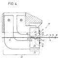
- the gap surfaces 26, 36 of the two that generate the gap 25 between them Deflection members 23, 33 have a profile that is different from one another.
- the gap surface 26 is convex and the other gap surface 36 concave.
- the gap width 39 recognizable in FIG. 4 can be significantly greater than the fabric thickness 38; this brings the two-sided Gap areas 26, 36 in different zones with the top and Bottom 16, 15 of the cut strips 10 'in contact.
- the convex Gap area 26 comes with its apex region 70 on the top of the web 16 to the system, while the support zones 71, 72 of the opposite support surface 36 the web underside 15 in the longitudinal offset touch.
- the support zones 71, 72 close the concave recess the gap surface 36 between them; in this concave recess there is no contact with the underside of the web 15
- Touch points 70 are not with the underside touch points 71, 72 aligned, but always longitudinally offset from each other.
- the top-side support in the apex region 70 is lower in height than the support zones 71, 72 of the underside of the web lying in front of and behind it 15. There is therefore a deflection of the treatment section in this area 40 versus its normally due to the longitudinal tension generated course of the stretch. That is vital.
- This deflection makes force components in the treatment section Longitudinal tension is effective, resulting in an automatic Pulling the web top 16 at the deflection 70 and the Serve underside 15 of the web at the support zones 71, 72; this will be there the rough enamel edges smoothed.
- the support zones 71, 72 can be straight be and follow the course of the track section 40. It understands yourself, if necessary, several such deflection points 70 to 72 and / or several deflection members 23, 33 can be provided. The pull-in force is increased if you have the redirection point lying on one side 70 compared to the 71, 72 lying on the other side even further transferred.
- a gap width 39 of approximately 1 mm is sufficient. Changes the fabric thickness 38 in the longitudinal course of the label tape 10 does not play Role. A height offset between the top and bottom deflection points 70 on the one hand and 71, 72 on the other hand of approximately 0.15 mm are sufficient.
- the deflection members 23, 33 are unheated, but so close to the fusion cutter 21 arranged that the edge regions 29 of the strips 10 'still are plastic.
- the fusion cutter is made in the present case from a heated wire 21, the wire ends are attached to the two deflection members 23, 33.
- These deflection links 23, 33 are made of metal and also serve as a conductor to the heating current to lead to wire 21.
- the longitudinal distance between the heating wire 91 and the first deflection point 71 is below 1 mm.
- the thread material 11, 14 of the Breitbahn can already be in the temperature range between Melt 160 ° C to 200 ° C.
- the heating wire 21 becomes dark Red hot heat and therefore reaches a temperature of over 400 ° C.
- the deflection members 23, 33 have the form of blocks here made of brass and are therefore good heat conductors. From the heated heating wire 21 therefore finds heat transfer to the two blocks 23, 33 instead, which drops indirectly to approx. 70 ° C in this way.
- the heating wire 21 is with the post-processing device 22 for the two melting edges created by this wire 21 adjacent Bands 10 'combined into a compact unit 30.
- This assembly 30 is part of a block 35, which has a plate shape, consists of insulation material and part of a housing 50 is.
- Two electrical connections protrude at the lower end of block 35 31, 32 out, which here consist of angular metal sheets, one 31 above and the other 32 below the Breitbahn 10 ends.
- the lower plate 32 carries the deflection member 33, which, as I said, is a block, but here has a wedge-shaped cross-sectional profile.
- the Wedge tip 34 of the support member 33 is directed downward from the Top of the web to facilitate the assembly of the block 35 on the Breitbahn 10.
- Das upper plate 31 is at the end with the upper block-shaped deflection member 23 provided, which is also a fastener 37 for the other end of the wire 21 has.
- a fastener 37 for the other end of the wire 21 has.
- 23 guide lugs 42 intended.
- An electrical cable 43 is led out at the upper end of the block 35, the electrical supply lines for the heating current of the wire 21st possesses that, which cannot be seen in more detail, in electrical connection stand with the aforementioned angular sheets 31, 32.
- the electrical Cable 43 may also include electrical control lines.
- the electrical Lines of the cable 43 are contacted with electrical components 44, which are arranged inside the block 35 and for heating control of the Serve wire 21.
- the electrical components 44 are expediently Part of an electrical circuit board 45, which is inside the block 35 is integrated.
- the circuit board 45 together with the components 44 and the protruding end of the cable 43 by means of a plastic compound be cast in a channel 46 of the block 35.
- function indicators 47 can sit, which protrude from block 35 and Z. B. make the thermal operating state of the wire 21 visible.
- the function displays 47 consist of a red one and a green glow lamp.
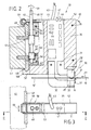
- the block 35 is part of a housing 50, which in the present case simply consists of two flat side plates 51, 52 exists, the distance 53 from each other simply by the plate thickness of the intermediate block 35 is determined.
- Block 35 becomes sandwich-like between the two side plates 51, 52 by fastening screws attached which holes 55 protrude in block 35 and both ends are anchored in the side plates 51, 52.
- the housing 50 is attached to the already mentioned support 41, the here consists of a support rail 41 running across the fabric.
- the mounting rail 41 has an upper one for holding the housing 50 and a lower profile bar 48, 49.
- the lower profile bar 48 has one Edge cross section, which is used to guide the housing 50 along the mounting rail 41 serves and in a corresponding angular cutout 58 at the rear End of the two housing side plates 51, 52 engages.
- the top profile bar 49 of the mounting rail 41 is in the case of attachment by a snap spring 59 engaged, which acts as a holding means of the housing 50.
- the snap spring 59 is, as shown in FIG.
- the snap spring 59 reaches behind a rear edge of the upper profile bar 49 and holds the housing 50 under spring tension positively on the mounting rail 41.
- the outbreak 57 of the plate-shaped block 35 is also yet another Insert 56, which acts as a guide on the front end face when installed the lower profile bar 48 is guided.
- This insert too 56 is provided with holes for fastening screws that the insert 56 sandwich between the two side plates 51, 52.
- the snap spring 59 can by a tool, for. B. a screwdriver, from their mounting position engaging behind the upper profile strip 49 Fig. 2 are solved.
- the housing 50 is in the sense of the pivot arrow 65 can be tilted away from the mounting rail 41 in order to remove it from the mounting rail 41 to be able to disassemble.
- the pivot point for this pivoting movement 65 then lies in the area of the described plate cutouts 58 on the lower one Profile bar 48.
- the housing 50 After pivoting away 65, the housing 50 also subtracted from the lower profile bar 48 and thus comfortably from the support rail 41 are removed.
- the assembly of the housing 50 on the mounting rail 41 takes place in the opposite sense.
- actuating means 60 are also provided on the housing 50, the to its longitudinal adjustment in the sense of the double arrow 66 along the Serve rail 41 as shown in FIG. 3. This is required to get the exact one Adjust the width of the strips 10 'to be cut.
- These positioning devices 60 comprise pinions 62, which have toothed racks provided on the mounting rail 41 61 are engaged.
- the racks 61 are on the front End face of the mounting rail 41 between the two profile strips mentioned 48, 49 arranged.
- the adjusting means 60 on the housing side are in the spacing space 53 arranged and located between the two side plates 51, 52 located in the outbreak 57 of the interposed already mentioned several times Blocks 35.
- the pinion 62 sit on a shaft 63, which with their Actuating end 68 protrudes at the upper end of the housing 50 and is pivoted in an upper and lower bearing 64, 67, which is in the mentioned insert pieces 54, 56. Through a turning tool the shaft 63 can be rotated in the direction of the actuating arrow 69 of FIG. 2, which causes the longitudinal adjustment 66 of the housing 50 on the mounting rail 41 is coming.
- a heat treatment is used to smooth the fabric after weaving referred to as "heat setting". This heat setting is best done in the area of the take-off roller 28.
- the devices 20 according to the invention do not need a loom 1 to be integrated. Instead of such an "on-loom” version the device could also be part of a cutting table where one previously made on a loom or on a knitting machine Broad web 10 can be subsequently cut into individual strips 10 ' should. In this case there is an "off-loom” version.
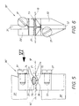
- FIG. 5 and 6 show in a side view analogous to FIG. 4 and in a front view illustrated by the arrow VI of FIG. 5 is a modified one Execution of the device according to the invention, also as a structural unit 30 'is designed, it is enough, only on the difference enter into.
- the Deflection members 23, 33 as already mentioned above, as metallic Blocks formed and therefore dimensionally stable.
- the described deflection surface 70 of FIG. 4 is therefore unyielding to the broadband 10.
- the assembly 30 'of FIGS. 5 and 6 are also similar blocks used as deflection members 23 ', 33, but which has a deflection member 23' a recess 74 in which there is an insert 73 made of elastic material located.
- the blocks 23 ', 33 are made of brass, used one for use 73 silicone.
- FIG. 7 shows a further alternative of the device according to the invention on the basis of a modified structural unit 30 ", specifically in one of the FIGS. 5 corresponding detailed representation.
- the difference to the first embodiment 30 is that the two here also block-shaped, metallic deflection members 23 ", 33" at their in contact with the tapes coming contact surfaces 76 provided with a flexible covering 77 are.
- This is also made of silicone or another elastic or heat resistant material.
- FIG. 8 shows a third embodiment of the invention Device based on a structural unit 30 '' ', which is largely the same as described above 5 and 6 corresponds to the first alternative, but in contrast is modified in that a concave shape in the underside Deflector as in the assembly 30 is missing.
- unit 30 '' ' there is a step at the lower deflection member 33 ', which is only one deflection point for the bands 10 'on their rear raised step surface 78. Due to the deflection, the bands 10 'at 78 with their undersides used while their tops, as in the embodiment 5, drawn against the resilient deflection surface of the cushion 73 become.
- the resilient pad surface 75 could tap the straps 10 'against the front Drag step surface 79 to create one at this point Preserve smoothing of the edge areas on the underside of the belt. If there the smoothing is sufficient, then the rear raised step surface could also 78 no longer apply.
- a meaning of the resilient deflection surfaces 75 made of elastic, bad heat-conducting material is that coming from the heated wire 21 still plastic edge areas of the strips 10 'at least on this deflection member 23 'or 23 "no longer the heat to the metallic components can dissipate in this area.
- Thermal insulation of such pillows 73 or coverings 77 is important. The deflection points then act on the still sufficiently plastic edge areas and lead for optimal smoothing. This heat insulation effect results especially when the contact surfaces 77, as in the third embodiment 30 '' 'of Fig. 7, on all their contact surfaces 76 with such coverings 77 are provided.
- FIG. 9 Another significance of the flexible deflection surfaces results from Fig. 9 and 10.
- the two have Heating wire 21 produced by the separating cut 24 individual bands 10 'of the original broad web a different band thickness in some areas 38, 38 '
- the patterns are namely in the case of label tapes 17 only in certain band zones 19, which are made by each other pattern-free longitudinal strips 19 are separated.
- the pattern 17 in the middle Band zones 18 require additional pattern threads, which is why there is a special one large fabric thickness 38 arises while in the intervening longitudinal stripes 19 results in a significantly smaller strip thickness 38 '.
- This can even, as Fig. 10 shows, in the direction of the width of the Vertical stripes 19 vary. This results in the bands 10 'z. B. the non-uniform strip profile 80 shown in FIG. 10.
- At least one deflection surface 75 of the upper deflection member 23 ' is an elastically flexible cushion surface 75, arises on the cushion 73 automatically a cushion profile 81 corresponding to the band profile 80. So there is a full-area contact in the edge areas, because the pillow profile 81 automatically adapts to the specified band profile 80 adapts. A particularly good edge smoothing is obtained on the belts 10 ', which leads to soft band edges.
Landscapes
- Engineering & Computer Science (AREA)
- Textile Engineering (AREA)
- Treatment Of Fiber Materials (AREA)
Description
- Fig. 1
- in perspektivischer, schematischer Darstellung verschiedene Arbeitsschritte, nämlich die Herstellung eines die Breitbahn bildenden Gewebes, das in Bänder zu zerschneiden ist, wobei, aus Gründen der Deutlichkeit, hier sowohl der Schmelzschneider als auch die Nachbearbeitungseinrichtung weggelassen worden sind,
- Fig. 2,
- in geschnittener Seitenansicht längs der Schnittlinie II-II von Fig. 3 und in Vergrößerung, eine kompakte Vorrichtung nach der Erfindung, die sowohl den Schmelzschneider als auch die Nachbehandlungseinrichtung besitzt,
- Fig. 3
- die Draufsicht auf die in Fig. 2 gezeigte Vorrichtung,
- Fig. 4,
- in einer der Fig. 2 entsprechenden Darstellung und in weiterer Vergrößerung, ein Detail der Vorrichtung,
- Fig. 5
- zeigt, anhand eines Details von Fig. 4, eine alternative Ausbildung der Vorrichtung nach der Erfindung,
- Fig. 6
- die Vorderansicht der Vorrichtung von Fig. 5 in Blickrichtung des Pfeiles VI,
- Fig. 7 und 8,
- in einer der Fig. 5 entsprechenden Darstellung, zwei weitere alternative Ausbildungen der Vorrichtung,
- Fig. 9
- in einer zu Fig. 6 zwar analogen Darstellung, aber in größerem Maßstab, die Vorderansicht der in Fig. 8 gezeigten Vorrichtung, und
- Fig. 10
- ein Teilstück der in Fig. 9 gezeigten Vorderansicht in weiterer Vergrößerung.
- 10
- Breitbahn
- 10'
- Band
- 11
- Kettfaden
- 12
- Webstelle
- 13
- Bahnbreite
- 14
- Schußfaden
- 15
- Unterseite von 10 bzw. 10'
- 16
- Oberseite von 10 bzw. 10'
- 17
- Muster
- 18
- Bandzone
- 19
- Längsstreifen
- 20
- Vorrichtung
- 21
- Schmeldzschneider, Draht
- 22
- Nachbearbeitungseinrichtung
- 23, 23', 23"
- oberseitiges Umlenkglied (Fig. 4, 5 bzw. 7)
- 24
- Trennschnitt
- 25
- Spalt
- 26
- konvexe Spaltfläche
- 27
- Längsbewegungs-Pfeil von 10, 10'
- 28
- Transporteinrichtung, Abzugswalze
- 29
- Schmelzkante von 10'
- 30, 30', 30"
- Baueinheit (Fig. 4, 5 bzw. 7)
- 30'''
- Baueinheit (Fig. 8 bis 10)
- 31
- Anschluß für 21, winkelförmiges Blech
- 32
- Anschluß für 21, winkelförmiges Blech
- 33, 33', 33"
- unterseitiges Umlenkglied
- 34
- Keilspitze von 33
- 35
- plattenförmiger Block für 50
- 36
- konkave Spaltfläche, konkave Form
- 37
- Befestigungsmittel für 21 an 33. 23
- 38
- Gewebedicke
- 38'
- Banddicke bei 19 (Fig. 10)
- 39
- Spaltweite
- 40
- Behandlungsabschnitt von 10' bei 22
- 41
- Träger für 20, Tragschiene
- 42
- Führungsnase für 21
- 43
- elektrisches Kabel
- 44
- elektrische Bauteile
- 45
- elektrische Leiterplatte für 44
- 46
- Kanal in 35
- 47
- Funktionsanzeigen an 35
- 48
- untere Profilleiste von 41
- 49
- obere Profilleiste von 41
- 50
- Gehäuse
- 51
- erste Seitenplatte von 50
- 52
- zweite Seitenplatte von 50
- 53
- Abstand zwischen 51, 52
- 54
- Einsatzstück für 59
- 55
- Bohrung in 35
- 56
- weiteres Einsatzstück in 53
- 57
- Ausbruch von 35
- 58
- Ausschnitt von 51. 52 für 48
- 59
- Schnappfeder an 50 für 49
- 60
- Stellmittel für 50 längs 41
- 61
- Zahnstange an 41
- 62
- Ritzel von 60
- 63
- Welle von 62
- 64
- oberes Lager von 63 in 54
- 65
- Schwenkbewegungspfeil von 50 (Fig. 2)
- 66
- Längsverstellung von 50 (Fig. 3)
- 67
- unteres Lager von 63 in 56
- 68
- Betätigungsende von 63
- 69
- Betätigungspfeil von 63
- 70
- erste Umlenkstelle. Scheitelhereich von 26. Umlenkfläche
- 71
- zweite Umlenkstelle, Stützzone von 36
- 72
- dritte Umlenkstelle, weitere Stützzone von 36
- 73
- Einsatz in 74 von 23', Kissen
- 74
- Aussparung in 23' (Fig. 5)
- 75
- nachgiebige Umlenkfläche von 73, Kissenaußenfläche (Fig. 5)
- 76
- Kontaktfläche von 23", 23"' bei 30'' (Fig. 9)
- 77
- Belag von 23'', 33'' (Fig 7)
- 78
- erhöhte hintere Stufenfläche von 33' (Fig. 8)
- 79
- vordere Stufenfläche von 33' (Fig. 8)
- 80
- Bandprofil, Band-Querprofil
- 81
- Kissenprofil von 73
Claims (19)
- Vorrichtung zum Trennen einer schmelzfähigen Breitbahn, vorzugsweise einem Gewebe (10) oder Gewirke, aus schmelzfähigem Fadenmaterial (11, 14), in mindestens zwei Bänder (10'), insbesondere in gemusterte Etikettbänder,dadurch gekennzeichnet,mit wenigstens einem Schmelzschneider (21) an der gewünschten Trennstelle (24) in der Breitbahn (10), um bei ihrer Längsbewegung (27) durch Schmelzen des Bahnmaterials zwei nebeneinander liegende Bänder (10') zu schneiden,ferner mit einer im Kantenbereich der geschnittenen Bänder (10') angreifenden Nachbearbeitungseinrichtung (22), welche die rauhen Schmelzkanten (29) glättet,und schließlich mit einer Transporteinrichtung (28), welche die Breitbahn (10) und die daraus geschnittenen Bänder (10') in Längsrichtung bewegt (27) und dabei wenigstens den im Bereich der Nachbearbeitungseinrichtung (22) befindlichen Behandlungsabschnitt (40) der Bänder (10') unter einer Längsspannung hält,daß die Nachbearbeitungseinrichtung (22) aus mehreren, an den Kantenbereichen der Bänder (10') im Behandlungsabschnitt (40) angreifenden Umlenkstellen (70, 71, 72) besteht,wobei die Umlenkstellen (70, 71, 72) sowohl in Längsbewegungsrichtung (27) der Bänder (10') als auch in ihrer Höhenrichtung zueinander versetzt sind und den Streckverlauf des bekannten Behandlungsabschnitts (40) verwinkeln,und daß die Längsspannung die Kantenbereiche der Bänder (10') im Behandlungsabschnitt (40) selbsttätig gegen die Umlenkstellen (70, 71, 72) zieht.
- Vorrichtung nach Anspruch 1, dadurch gekennzeichnet, daß die Umlenkstellen (70, 71, 72) aus Umlenkgliedern (23, 33) bestehen, die zwischen sich einen freien Spalt (25) schließen, wobei der Behandlungsabschnitt (40) durch den Spalt (25) ungeklemmt hindurch läuft.
- Vorrichtung nach Anspruch 1 oder 2, dadurch gekennzeichnet, daß die Umlenkglieder (23, 33) im wesentlichen ortsfest angeordnet und in sich formsteif ausgebildet sind.
- Vorrichtung nach Anspruch 1 oder 2, dadurch gekennzeichnet, daß wenigstens eines der Umlenkglieder (23') eine elastisch nachgiebige Umfangsfläche (75) für die Bänder (10' aufweist.
- Vorrichtung nach Anspruch 4, dadurch gekennzeichnet, daß das Umlenkglied (23", 33") einen nachgiebigen Belag (77) an seiner mit den Bändern (10') in Berührung kommenden Kontaktfläche (76) besitzt.
- Vorrichtung nach Anspruch 4, dadurch gekennzeichnet, daß das Umlenkglied (23') einen als elastisches Kissen (73) ausgebildeten Einsatz aufweist und die Außenfläche (75) des Kissens mit den Bändern (10') in Berührung steht.
- Vorrichtung nach einem oder mehreren der Ansprüche 4 bis 6, wobei die Bänder, aufgrund ihrer veränderlichen Banddicke (38, 38'), in ihrer Transportrichtung und/oder quer dazu, ein stellenweise unterschiedliches Band-Längsprofil bzw. Band-Querprofil (80) aufweisen,
dadurch gekennzeichnet, daß die elastisch nachgiebige Umfangsfläche (75) des Umlenkglieds (23') sich dem Bandprofil selbsttätig anpaßt (81). - Vorrichtung nach einem oder mehreren der Ansprüche 1 bis 7, dadurch gekennzeichnet, daß die Umlenkstelle (70, 71, 72) nur aus einem oberseitigen und aus einem unterseitigen Umlenkglied (23, 33) bestehen, und die Umlenkglieder (23, 33) zwei, den dazwischen liegenden Spalt (25) erzeugende Spaltflächen (26, 36) aufweisen, von denen die eine Spaltfläche (36) konkav und die andere (26) konvex ausgebildet sind.
- Vorrichtung nach einem oder mehreren der Ansprüche 1 bis 8, dadurch gekennzeichnet, daß die Umlenkglieder (23, 33) zwar selbst unbeheizt, aber so nahe an dem Schmelzschneider (21) angeordnet sind, daß die Kantenbereiche (29) der Bänder (10') an ihren Umlenkflächen noch plastisch sind.
- Vorrichtung nach Anspruch 8 oder 9, dadurch gekennzeichnet, daß der Schmelzschneider aus einem beheizten Draht (21) besteht, dessen eines Drahtende an dem oberseitigen (23) und dessen anderes Drahtende an dem unterseitigen Umlenkglied (33) befestigt sind.
- Vorrichtung nach einem oder mehreren der Ansprüche 1 bis 10, dadurch gekennzeichnet, daß die beiden Umlenkglieder (23, 33) zugleich Leiter für den Heizstrom des Schmelzschneiders (21) sind.
- Vorrichtung nach einem oder mehreren der Ansprüche 1 bis 11, dadurch gekennzeichnet, daß der Schmelzschneider (21) und die Umlenkglieder (22, 23) eine vormontierte, kompakte Baueinheit (30) bilden und diese Baueinheit (30) an der gewünschten Trennstelle (24) der Breitbahn (10) montierbar ist.
- Vorrichtung nach Anspruch 12, dadurch gekennzeichnet, daß die Baueinheit (30) Bestandteil eines Blocks (35) ist, wobei der Block (35) an einem die Breitbahn (10) überquerenden Träger (41) sitzt und - zur Einstellung der gewünschten Breite der auszuschneidenden Bänder (10') - entlang des Trägers verstellbar (66) ist.
- Vorrichtung nach Anspruch 13, dadurch gekennzeichnet, daß wenigstens einige elektrische Bauteile (44), die zur Heizsteuerung des Schmelzschneiders (21) dienen, in den jeweiligen Block (35) integriert sind.
- Vorrichtung nach Anspruch 13 oder 14, dadurch gekennzeichnet, daß am Block (35) Funktionsanzeigen (47) für den thermischen und/oder mechanischen Betriebszustand des zugehörigen Schmelzscheiders (21) integriert sind.
- Vorrichtung nach einem oder mehreren der Ansprüche 13 bis 15, dadurch gekennzeichnet, daß der Block (35) Plattenform aufweist und Bestandteil eines aus zwei voneinander beabstandeten Seitenplatten (51, 52) bestehenden Gehäuses (50) ist,daß der Block (35) aus Isolationsmaterial besteht und im Abstandsraum (53) zwischen den beiden Seitenplatten (51, 52) des Gehäuses (50) befestigt ist,wobei der Block (35) elektrische Anschlüsse für den Schmelzschneider (21) besitzt und ggf. die elektrischen Bauteile (44) zur Heizsteuerung des Schmelzschneiders (21) beinhaltet,und daß das Gehäuse (50) die Haltemittel (58, 59) zur Anbringung des Blocks (35) an dem Träger (41) und ggf. die Stellmittel (60) zur Längsverstellung (41) des Blocks (35) am Träger (41) trägt.
- Vorrichtung nach Anspruch 16, dadurch gekennzeichnet, daß die Haltemittel (59) und ggf. die Stellmittel (60) im Abstandsraum (53) zwischen den beiden Seitenplatten (51, 52) des Gehäuses (50) angeordnet sind.
- Vorrichtung nach einem oder mehreren der Ansprüche 1 bis 17, dadurch gekennzeichnet, daß die Baueinheit (30) bzw. der die Baueinheit (30) aufweisende Block (35) in eine Webmaschine integriert sind, auf welcher die Breitbahn (10) hergestellt wird.
- Vorrichtung nach einem oder mehreren der Ansprüche 1 bis 17, dadurch gekennzeichnet, daß die Baueinheit (30) bzw, der die Baueinheit (30) aufweisende Block (35) Bestandteil eines Schneidtisches sind, der eine anderweitig hergestellte Breitbahn (10) nachträglich in einzelne Bänder (10') zu zerschneiden gestattet.
Applications Claiming Priority (3)
| Application Number | Priority Date | Filing Date | Title |
|---|---|---|---|
| DE19644534 | 1996-10-26 | ||
| DE1996144534 DE19644534C2 (de) | 1996-10-26 | 1996-10-26 | Vorrichtung zum Längstrennen einer schmelzfähigen Breitbahn in mindestens zwei Bändern, insbesondere in gemusterte Etikettbänder |
| PCT/EP1997/005737 WO1998018995A1 (de) | 1996-10-26 | 1997-10-17 | Vorrichtung zum trennen einer schmelzfähigen breitbahn in mindestens zwei bänder, insbesondere in gemusterte etikettbänder |
Publications (2)
| Publication Number | Publication Date |
|---|---|
| EP0934437A1 EP0934437A1 (de) | 1999-08-11 |
| EP0934437B1 true EP0934437B1 (de) | 2001-07-11 |
Family
ID=7810067
Family Applications (1)
| Application Number | Title | Priority Date | Filing Date |
|---|---|---|---|
| EP97948760A Expired - Lifetime EP0934437B1 (de) | 1996-10-26 | 1997-10-17 | Vorrichtung zum trennen einer schmelzfähigen breitbahn in mindestens zwei bänder, insbesondere in gemusterte etikettbänder |
Country Status (4)
| Country | Link |
|---|---|
| US (1) | US6207930B1 (de) |
| EP (1) | EP0934437B1 (de) |
| DE (2) | DE19644534C2 (de) |
| WO (1) | WO1998018995A1 (de) |
Cited By (2)
| Publication number | Priority date | Publication date | Assignee | Title |
|---|---|---|---|---|
| WO2004070103A1 (de) * | 2003-02-06 | 2004-08-19 | Textilma Ag | Schneidvorrichtung zum thermischen schneiden einer laufenden, insbesondere gemusterten textilbahn |
| CN101429723B (zh) * | 2008-06-08 | 2010-12-08 | 岳睿 | 印刷缎带分割机械装置 |
Families Citing this family (9)
| Publication number | Priority date | Publication date | Assignee | Title |
|---|---|---|---|---|
| CA2316696C (en) * | 2000-08-25 | 2006-10-31 | Steven John Smirle | Device for thermally cutting a moving web of textile material |
| CH697695B1 (de) * | 2003-02-06 | 2009-01-15 | Textilma Ag | Schneidvorrichtung zum thermischen Schneiden einer laufenden, insbesondere gemusterten Textilbahn. |
| DE102007036503B3 (de) * | 2007-08-01 | 2009-02-26 | Vaupel Textilmaschinen Gmbh & Co. Kg | Vorrichtung zum Weben eines Breitgewebes und zum Trennen des Breitgewebes in Bänder |
| US20090113681A1 (en) * | 2007-11-07 | 2009-05-07 | Yidi Jr Carlos | Method of Making Soft Edge Textile Labels to be Applied to Garments |
| DE102012009871B3 (de) * | 2012-05-16 | 2013-08-29 | Vaupel Textilmaschinen Gmbh & Co. Kg | Vorrichtung zur Thermofixierung von Bändern, insbesondere von Etikettenbändern, die auseiner schmelzfähiges Material aufweisenden Breitbahn erzeugt sind |
| DE102013006413B4 (de) | 2013-04-13 | 2015-10-01 | Vaupel Textilmaschinen Gmbh & Co. Kg | Vorrichtung zur Thermofixierung einer schmelzfähiges Material aufweisenden textilen Bahn |
| KR20180081275A (ko) * | 2017-01-06 | 2018-07-16 | 주식회사 팜한농 | 3-아릴우라실 화합물의 제조 방법 |
| EP3722471A1 (de) | 2019-04-10 | 2020-10-14 | Textilma AG | Verfahren zum herstellen von kaltgeschnittenen gewebebahnen |
| CN113073459B (zh) * | 2021-03-04 | 2022-07-19 | 杭州驰远家用纺织品有限公司 | 一种纺织生产用的绒制品切边装置 |
Family Cites Families (12)
| Publication number | Priority date | Publication date | Assignee | Title |
|---|---|---|---|---|
| DD38545A (de) * | ||||
| DE2300686A1 (de) | 1973-01-08 | 1974-07-11 | Engel Gmbh | Vorrichtung zum schneiden und trennen von warenbahnen aus vollsynthetischen fasern unter verschweissen der schnittraender |
| US4069727A (en) * | 1974-11-27 | 1978-01-24 | Rospatch Corporation | Separation of label tape into labels |
| DE2516057A1 (de) | 1975-04-12 | 1976-10-28 | Mageba Textilmaschinen Gmbh | Eine der abzugseinrichtung eines webstuhles nachgeordnete schneidvorrichtung |
| US4384908A (en) * | 1982-04-26 | 1983-05-24 | Kleist William E | Apparatus and method for cutting, shouldering and sealing strip webbing |
| GB2139937B (en) * | 1983-05-13 | 1986-12-10 | Electricity Council | A cut finishing device |
| WO1989002491A1 (fr) * | 1987-09-21 | 1989-03-23 | Textilma Ag | Metier a tisser |
| DE4011293A1 (de) * | 1989-04-12 | 1990-10-18 | Loepfe Ag Geb | Vorrichtung zum thermischen trennen von textilen flaechengebilden |
| CH678953A5 (en) | 1989-04-12 | 1991-11-29 | Loepfe Ag Geb | Installation for thermal cutting of textiles |
| DE9219185U1 (de) * | 1991-07-18 | 1999-05-20 | Textilma Ag, Hergiswil | Webmaschine zur Herstellung von Etikettenbändern |
| DE19510818C1 (de) * | 1995-03-24 | 1996-07-04 | Volker Keith | Widerstandsbeheizte Trennvorrichtung für textile Bahnen |
| EP0853697B1 (de) | 1995-10-04 | 1999-10-20 | VAUPEL TEXTILMASCHINEN GmbH & Co. KG. | Vorrichtung zum herstellen von vorzugsweise gemusterten textilen bändern, insbesondere von etikettbändern, aus einer schmelzfähiges material aufweisenden breitbahn |
-
1996
- 1996-10-26 DE DE1996144534 patent/DE19644534C2/de not_active Expired - Fee Related
-
1997
- 1997-10-17 US US09/284,931 patent/US6207930B1/en not_active Expired - Fee Related
- 1997-10-17 DE DE59704036T patent/DE59704036D1/de not_active Expired - Lifetime
- 1997-10-17 WO PCT/EP1997/005737 patent/WO1998018995A1/de not_active Ceased
- 1997-10-17 EP EP97948760A patent/EP0934437B1/de not_active Expired - Lifetime
Cited By (2)
| Publication number | Priority date | Publication date | Assignee | Title |
|---|---|---|---|---|
| WO2004070103A1 (de) * | 2003-02-06 | 2004-08-19 | Textilma Ag | Schneidvorrichtung zum thermischen schneiden einer laufenden, insbesondere gemusterten textilbahn |
| CN101429723B (zh) * | 2008-06-08 | 2010-12-08 | 岳睿 | 印刷缎带分割机械装置 |
Also Published As
| Publication number | Publication date |
|---|---|
| DE19644534C2 (de) | 2001-03-22 |
| EP0934437A1 (de) | 1999-08-11 |
| DE59704036D1 (de) | 2001-08-16 |
| DE19644534A1 (de) | 1998-04-30 |
| WO1998018995A1 (de) | 1998-05-07 |
| US6207930B1 (en) | 2001-03-27 |
Similar Documents
| Publication | Publication Date | Title |
|---|---|---|
| EP0934437B1 (de) | Vorrichtung zum trennen einer schmelzfähigen breitbahn in mindestens zwei bänder, insbesondere in gemusterte etikettbänder | |
| DE3303504C2 (de) | Vorrichtung zum Verkleben flächenförmiger Textilstücke | |
| DE2236445C3 (de) | Ausgangsmaterial für Textilersatzstoffe | |
| EP0389793B1 (de) | Verfahren und Vorrichtung zur Herstellung einer Schar paralleler, insbesondere gemusterter, Etikettbänder | |
| EP0333781B1 (de) | Webmaschine | |
| EP0503249A1 (de) | Entwässerungseinrichtung für die Nasspartie einer Papiermaschine | |
| DE3937947C2 (de) | ||
| DE4011293A1 (de) | Vorrichtung zum thermischen trennen von textilen flaechengebilden | |
| DE10036821B4 (de) | Vorrichtung zum Mustern einer Filzbahn durch ein Nadeln mit einer Nadelungseinrichtung | |
| DE202009013550U1 (de) | Schneidbügel für ein Heizdrahtschneidgerät sowie Heizdrahtschneidgerät | |
| EP0853697B1 (de) | Vorrichtung zum herstellen von vorzugsweise gemusterten textilen bändern, insbesondere von etikettbändern, aus einer schmelzfähiges material aufweisenden breitbahn | |
| DE2931167C2 (de) | Vorrichtung zum kompressiven Schrumpfen einer textilen Warenbahn | |
| EP0792966B1 (de) | Kalander zum Satinieren von Papier | |
| DE3815395A1 (de) | Webmaschine | |
| DE102007036503B3 (de) | Vorrichtung zum Weben eines Breitgewebes und zum Trennen des Breitgewebes in Bänder | |
| EP0705925A2 (de) | Heizeinrichtung mit auswechselbaren Fadenführern | |
| CH678953A5 (en) | Installation for thermal cutting of textiles | |
| DE4115800A1 (de) | Verfahren und vorrichtung zur herstellung eines durch figurschuss gemusterten textilen bandes, insbesondere eines etikettbandes, aus einer breitbahn mit schmelzfaehigem fadenwerkstoff | |
| EP0515717B1 (de) | Vorrichtung zum Herstellen einer Überdecknaht in oder an Nähmaschinen mit mehreren Nadeln | |
| DE7334973U (de) | Vorrichtung zur herstellung einer geschichteten, wenigstens zwei miteinander vernadelte schichten aus nichtgewebtem faservliesmaterial aufweisenden bahn | |
| DE102006061140A1 (de) | Vorrichtung zum thermischen Schneiden einer aus schmelzfähigem Fadenmaterial bestehenden Textilbahn in Bänder | |
| DE10011570A1 (de) | Vorrichtung zum Herstellen von vorzugsweise gemusterten textilen Bändern aus einer schmelzfähiges Material aufweisenden Breitbahn | |
| DE2050377B2 (de) | ||
| DE19948955B4 (de) | Bahnschneidvorrichtung mit einer integrierten Messeranordnung in einer Rollenrotationsdruckmaschine | |
| DE2952655C2 (de) | Fadenführerbefestigung bei Kettenwirkmaschinen |
Legal Events
| Date | Code | Title | Description |
|---|---|---|---|
| PUAI | Public reference made under article 153(3) epc to a published international application that has entered the european phase |
Free format text: ORIGINAL CODE: 0009012 |
|
| 17P | Request for examination filed |
Effective date: 19990227 |
|
| AK | Designated contracting states |
Kind code of ref document: A1 Designated state(s): CH DE IT LI |
|
| GRAG | Despatch of communication of intention to grant |
Free format text: ORIGINAL CODE: EPIDOS AGRA |
|
| 17Q | First examination report despatched |
Effective date: 20001110 |
|
| GRAG | Despatch of communication of intention to grant |
Free format text: ORIGINAL CODE: EPIDOS AGRA |
|
| GRAH | Despatch of communication of intention to grant a patent |
Free format text: ORIGINAL CODE: EPIDOS IGRA |
|
| GRAH | Despatch of communication of intention to grant a patent |
Free format text: ORIGINAL CODE: EPIDOS IGRA |
|
| GRAA | (expected) grant |
Free format text: ORIGINAL CODE: 0009210 |
|
| AK | Designated contracting states |
Kind code of ref document: B1 Designated state(s): CH DE IT LI |
|
| REG | Reference to a national code |
Ref country code: CH Ref legal event code: NV Representative=s name: ISLER & PEDRAZZINI AG Ref country code: CH Ref legal event code: EP |
|
| ITF | It: translation for a ep patent filed | ||
| REF | Corresponds to: |
Ref document number: 59704036 Country of ref document: DE Date of ref document: 20010816 |
|
| PLBE | No opposition filed within time limit |
Free format text: ORIGINAL CODE: 0009261 |
|
| STAA | Information on the status of an ep patent application or granted ep patent |
Free format text: STATUS: NO OPPOSITION FILED WITHIN TIME LIMIT |
|
| 26N | No opposition filed | ||
| REG | Reference to a national code |
Ref country code: CH Ref legal event code: PCAR Free format text: ISLER & PEDRAZZINI AG;POSTFACH 1772;8027 ZUERICH (CH) |
|
| PGFP | Annual fee paid to national office [announced via postgrant information from national office to epo] |
Ref country code: CH Payment date: 20081027 Year of fee payment: 12 |
|
| PGFP | Annual fee paid to national office [announced via postgrant information from national office to epo] |
Ref country code: IT Payment date: 20081022 Year of fee payment: 12 |
|
| REG | Reference to a national code |
Ref country code: CH Ref legal event code: PL |
|
| PG25 | Lapsed in a contracting state [announced via postgrant information from national office to epo] |
Ref country code: LI Free format text: LAPSE BECAUSE OF NON-PAYMENT OF DUE FEES Effective date: 20091031 Ref country code: CH Free format text: LAPSE BECAUSE OF NON-PAYMENT OF DUE FEES Effective date: 20091031 |
|
| PG25 | Lapsed in a contracting state [announced via postgrant information from national office to epo] |
Ref country code: IT Free format text: LAPSE BECAUSE OF NON-PAYMENT OF DUE FEES Effective date: 20091017 |
|
| PGFP | Annual fee paid to national office [announced via postgrant information from national office to epo] |
Ref country code: DE Payment date: 20120814 Year of fee payment: 16 |
|
| REG | Reference to a national code |
Ref country code: DE Ref legal event code: R119 Ref document number: 59704036 Country of ref document: DE Effective date: 20140501 |
|
| PG25 | Lapsed in a contracting state [announced via postgrant information from national office to epo] |
Ref country code: DE Free format text: LAPSE BECAUSE OF NON-PAYMENT OF DUE FEES Effective date: 20140501 |