EP0934686B1 - Vorrichtung zum halten einer eingabeeinheit - Google Patents
Vorrichtung zum halten einer eingabeeinheit Download PDFInfo
- Publication number
- EP0934686B1 EP0934686B1 EP97947701A EP97947701A EP0934686B1 EP 0934686 B1 EP0934686 B1 EP 0934686B1 EP 97947701 A EP97947701 A EP 97947701A EP 97947701 A EP97947701 A EP 97947701A EP 0934686 B1 EP0934686 B1 EP 0934686B1
- Authority
- EP
- European Patent Office
- Prior art keywords
- input unit
- movement
- guide element
- holding
- appliance
- Prior art date
- Legal status (The legal status is an assumption and is not a legal conclusion. Google has not performed a legal analysis and makes no representation as to the accuracy of the status listed.)
- Expired - Lifetime
Links
Images


Classifications
-
- G—PHYSICS
- G03—PHOTOGRAPHY; CINEMATOGRAPHY; ANALOGOUS TECHNIQUES USING WAVES OTHER THAN OPTICAL WAVES; ELECTROGRAPHY; HOLOGRAPHY
- G03G—ELECTROGRAPHY; ELECTROPHOTOGRAPHY; MAGNETOGRAPHY
- G03G15/00—Apparatus for electrographic processes using a charge pattern
- G03G15/50—Machine control of apparatus for electrographic processes using a charge pattern, e.g. regulating differents parts of the machine, multimode copiers, microprocessor control
- G03G15/5016—User-machine interface; Display panels; Control console
-
- H—ELECTRICITY
- H02—GENERATION; CONVERSION OR DISTRIBUTION OF ELECTRIC POWER
- H02B—BOARDS, SUBSTATIONS OR SWITCHING ARRANGEMENTS FOR THE SUPPLY OR DISTRIBUTION OF ELECTRIC POWER
- H02B1/00—Frameworks, boards, panels, desks, casings; Details of substations or switching arrangements
- H02B1/26—Casings; Parts thereof or accessories therefor
- H02B1/30—Cabinet-type casings; Parts thereof or accessories therefor
- H02B1/32—Mounting of devices therein
- H02B1/34—Racks
- H02B1/36—Racks with withdrawable units
-
- H—ELECTRICITY
- H05—ELECTRIC TECHNIQUES NOT OTHERWISE PROVIDED FOR
- H05K—PRINTED CIRCUITS; CASINGS OR CONSTRUCTIONAL DETAILS OF ELECTRIC APPARATUS; MANUFACTURE OF ASSEMBLAGES OF ELECTRICAL COMPONENTS
- H05K7/00—Constructional details common to different types of electric apparatus
- H05K7/14—Mounting supporting structure in casing or on frame or rack
- H05K7/1401—Mounting supporting structure in casing or on frame or rack comprising clamping or extracting means
- H05K7/1411—Mounting supporting structure in casing or on frame or rack comprising clamping or extracting means for securing or extracting box-type drawers
Definitions
- the invention relates to a device for holding an input unit for entering control data for an electrical Device, especially on a printer or copier.
- Printers and copiers are known in which the input unit, e.g. a keyboard and possibly an associated one Display unit is attached to the outside of the printer.
- the keyboard are determined when the printer operates properly Operating modes selected. For example, the number too printing sheets, the print format or a specific one Print type (simplex, duplex) can be selected. A malfunction occurs in the printer, so through the keyboard a qualified operator enter tax data that is too localization or elimination of the error.
- the disadvantage is that the keyboard is relatively unprotected, so that unwanted entries can also be made, e.g. by supporting by operators on the keyboard or by dropping of objects.
- keyboards made from a mechanical Bracket can be removed from the printer and into a panel of the device can be attached with holding elements.
- an operator has a number of How easy it is to operate the printer worsen.
- DE 43 31 110 A1 is a pull-out for a control cabinet Holding device known. Because of the inclined However, the design of the held keyboard becomes a large installation space needed in the control cabinet. This also applies to the im Utility model DE-U- 82 12 927 addressed on a pad pull-out keyboard of a data processing system.
- a pull-out keyboard is known from DE 31 03 481 C2, which, however, moves along a curved path must become.
- US-A-4,718,740 is a device for holding a Input unit known that a keyboard for entering data includes.
- the device is together with a display unit pivotable about a pivot axis.
- the device can from a vertical resting position to an approximate one horizontal operating position can be pivoted.
- US-A-5,388,032 and GB-A-2,133,222 describe one similar device, the input unit with a keyboard can only be moved in a horizontal plane. In the rest position, the input unit may be together pushed into a device with a display unit.
- a device of the type mentioned Art solved in that they have at least one at the Input unit arranged guide element, which of a receiving element arranged on the device is movably received is.
- the input unit is essentially in a level between a rest position and an operating position movable. In the rest position, the input unit is inside the device is stored and in the operating position Input unit can be operated from the outside.
- the invention is based on the consideration that an operator of the printer or copier only then should be available when the operator actually Want to enter tax data and / or to enter tax data is authorized or qualified.
- a guide element arranged, which is a movement the input unit on a level between the rest position and the operating position.
- the operator can thus supports the input unit through the guide element move linearly. This linear movement is very simple, so that it can be operated by the operator even at high speed can be executed.
- the input unit must thus not be guided along a curved path or hooked into a given position. Consequently The invention enables quick access to the input unit.
- the input unit in the invention is in the rest position stored within the device so that accidental actuation effectively prevented by covering the device becomes.
- the input unit is thus in the rest position hardly visible on the outside or not at all.
- the number of visible Controls are reduced, so that the operation of the Device simplified.
- the input unit can be operated freely from the outside, so that the operator has an ergonomically appropriate freedom of work Has.
- the receiving element is horizontal arranged inclined so that the input unit also in the Operating position is slightly inclined.
- the inclination is dependent the height at which the input unit is arranged. It is chosen so that when entering the tax data an ergonomic working position for the operator results. Due to the inclination of the receiving element, the The input unit itself is flat and therefore space-saving become.
- the guide element arranged in an edge area of the input unit and a second guide member is on an opposite one Edge area of the input unit arranged. Holding the Input unit is very easy with the help of two guide elements stable possible, so that pressure forces when entering the control data be well compensated and the input unit when entering lies quietly.
- a locking element in its position in the operating position a locking element is fixed, so forces when entering the control data occur in the direction of movement of the input unit, without it changing its position.
- a lever connected to the locking element, which ends near the input unit, makes operation easier of the locking element.
- the locking element can be designed so that a reset element, such as. a spring, the locking element automatically in a normal position, which is also when fixing the Guide element is taken.
- the restoring force can for braking the input unit when moving to the rest position or used in the working position. To are in the range of movement of the sloping locking element to which the locking element shortly before reaching the rest position or the operating position of the input unit and is pushed out of its normal position, with increasing Distance to the normal position an increasing braking force developed on the slopes, which due to the connection the movement of the locking element and input unit the input unit is braked. This braking of the input unit leads to an increase in the durability of the Holding device because of high mechanical loads Impact when reaching the rest position or the operating position be avoided.
- the input unit is also by the Braking device when reaching the rest position or the Operating position protected from vibrations that lead to a Damage to the input unit.
- a braking device stop bodies made of elastic material are also used, which are preferably arranged on stop surfaces of the guides are.
- Actuator and braking device are in one embodiment the invention coupled so that the Brake device unlocked when actuating the actuating element becomes. This measure is moving the Input unit possible with little friction. As long as the input unit is guided by the hand of the operator this is the speed of movement of the input unit. The input unit slips out of the operator's hand or if it is released, the actuator is not more actuated and the braking device effective, creating a Bouncing the keyboard when it reaches the rest or operating position is prevented.
- a locking device is arranged, the moving the input unit in the operating position prevented, so access to the input unit can be effectively restricted.
- the only locking device is used to cover the device with a tool, which is solved anyway by the service staff in case of service must become. This means that only a qualified person can perform a service Enter control data via the input unit so that in particular incorrect operation by unqualified people excluded are.
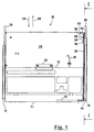
- FIG. 1 shows a top view of a holding device 10 for holding a keyboard 12, e.g. a well-known personal computer keyboard.
- a keyboard 12 e.g. a well-known personal computer keyboard.
- An operator uses the keyboard 12
- Control data for a printer (see FIG. 3) entered, on the frame of two guide shots 14, 16 are attached.
- the control data is from the keyboard 12 via a connecting line 18 to a central control unit of the printer.
- the keyboard 12 is on one Base plate 20 attached using a mounting plate 22.
- the base plate 20 is on both sides of the keyboard 12 angled so that on the one hand their bending stiffness increases is and on the other fastening options for telescopic rails 24 and 26 arise.
- the telescopic rail 24 is from the guide receptacle 14 and the telescopic rail 26 from the Guide receptacle 16 includes so that the base plate 20 together with the keyboard 12 in the through the base plate 20th fixed level along the guide receptacles 14, 16 moves can be, cf. Arrows 28 and 29.
- the keyboard is shown in a rest position, in which the telescopic rails 24 and 26 essentially are located within the guide receptacles 14 and 16. If the keyboard is moved in the direction of arrow 29, so the telescopic rails 24 and 26 until reaching one Operating position guided by the guide seats 14 and 16, until almost the entire length of the guide shots 14 and 16 protrude.
- actuating element 32 for actuating a locking element 34 via a lever 36.
- the operation of the actuating element 32, the locking element 34 and the lever 36 is explained below with reference to FIG. 2.
- the locking element 34 is rotatably supported at an angle 38 about an axis of rotation 40.
- the angle 38 is via a hollow rivet connection 42 with the Base plate 20 connected.
- Another recess 48 is located on the printer facing away End of the sheet 60 (see. Fig. 2).
- the recording 48 takes the locking element 34 in the operating position, so that again the base plate 20 with respect to the guide receptacles 14 and 16 and thus fixed with respect to the entire printer is.
- Fig. 2 shows in part a a sectional view of the holding device 10 along the section I of FIG. 1.
- Die Recess 48 is in an angular sheet 60, which is attached to the guide receptacle 16 as below explained using part c of FIG. 2. From the sheet 60 bevels 62 and 64 protrude in opposite directions fall off.
- a sheet 66 on the other side of the holder 10 is between the guide receptacle 14 and the frame attached to the printer, but has no slots and slopes.
- the locking element 34 has a projection 68, which is by the spring 44 is pressed in the direction of an arrow 69, so that in the rest position the protrusion protruding through the recess 46 between a stop surface 70 and 72 of the sheet 60 is arranged so that when the base plate 20 in the direction of arrow 29, the projection 68 on the stop surface 70 and when moving in the direction of arrow 28 the stop surface 72 abuts.
- the locking element 34 is released by the actuating element 32 is moved away from the printer by an operator.
- the Movement of the actuating element 32 is via the lever 36 transferred up to the locking element 34.
- the lever 36 is on one end via a bearing 74 with the actuator 32 and at its other end via a bearing 76 with the Locking element 34 connected. If the actuator 32nd actuated, the locking element 34 moves in the direction of Arrow 78, whereby the projection 68 is raised so far, that now a movement of the base plate 20 in the direction of Arrow 29 is possible. The projection 68 therefore does not bump more to the stop surface 70 when the base plate 20 in the operating position is pulled.
- the slopes 62 and 64 serve as a braking device if when moving the base plate 20 into the rest position or in the operating position no longer actuates the actuating element 32 becomes.
- the projection 68 is by the spring 44 pressed back into its normal position and comes to the Reaching the operating position with the slope 62 and when reaching the rest position in contact with the slope 64.
- the Bevels 62 and 64 force the projection towards the Arrow 78 against the spring force of the spring 44.
- the spring 44 acts as a brake with increasing deflection of the projection 68.
- Fig. 2 shows in part b an enlargement of the contact surface 30 according to the sectional view of part a of FIG. 2.
- the contact surface 30 is an extension of the base plate 20 and bent so that a cavity 90 is formed, in which the actuator 32 attached to a hinge 92 is that with the other hinge surface on the support surface 30 is attached.
- the actuator 32 in Direction of an arrow 94 through the fingers 96 of an operator be pressed.
- the outer surface of the contact surface 30 as a counter pressure surface for a thumb 98 of the operator serve.
- the actuating element is in the direction of an arrow 100 32 by the spring force of the spring 44, the is transmitted via the latching element 34 and the lever 36.
- Part c of Fig. 2 shows a sectional view of the holding device 10 along the section II according to part a of FIG. 2, which is transverse to the direction of movement 28, 30 of the base plate 20 lies.
- the locking element 34 is in one Position P1 according to part a of Fig. 2.
- Between the telescopic rail 26 and guide receptacle 16 are balls 110 and 112, which the friction when moving the base plate 20th belittle.
- the locking element 34 is on a bolt 114 with the aid of a Locking ring 116 attached.
- the bolt 114 is stationary connected to the angle 38.
- a bolt 118 connects the Lever 36 and the locking element 34.
- a locking ring holds 120 the lever 36 and the pin 118 close together, however, a rotational movement between lever 36 and locking element 34 is made possible.
- FIG. 3 shows in part a the arrangement of the holding device 10 in printer 130.
- Printer 130 has a frame 132, on which the holding device 10 at an angle of about 20 degrees to the horizontal.
- On the frame 132 is also a vertically pivotable display unit 134 is attached, displays and displays the operating states of printer 130 actuators 136, e.g. for switching on and off of the printer 130.
- the printer 130 is protected from environmental influences by a cover 138 protected.
- a cover 138 In the area of the display unit 134 and the Holding device 10 is the panel through a door 140 formed, which is a window 142 for the display unit 134 Has. When the door 140 is closed, the keyboard is accessible 12 not possible.
- Part b of FIG. 3 shows printer 130 with the door open 140, which only by a qualified person for service purposes is opened.
- the keyboard is also used for the service 12 used so that the qualified operator Base plate 20 in the manner described above in the operating position pulls. Is in the operating position the keyboard 12 below the display unit 134 between the operator and display unit 134 so that certain operating states printer 130 from the keyboard by entering Tax data are queried.
- the display unit 134 shows the current operating states then on.
- the keyboard 12 is back pushed into the rest position. After that, the door 140 again closed, so that only for the operation of the printer 130 the actuators 136 are still accessible.
Landscapes
- Engineering & Computer Science (AREA)
- Microelectronics & Electronic Packaging (AREA)
- Power Engineering (AREA)
- Physics & Mathematics (AREA)
- General Physics & Mathematics (AREA)
- Accessory Devices And Overall Control Thereof (AREA)
Abstract
Description
- Figur 1
- eine Draufsicht auf eine Haltevorrichtung zum Halten einer Tastatur,
- Figur 2
- Schnittdarstellungen der Haltevorrichtung, und
- Figur 3
- die Anordnung der Haltevorrichtung in einem Drucker.
- 10
- Haltevorrichtung
- 12
- Tastatur
- 14, 16
- Führungsaufnahme
- 18
- Verbindungsleitung
- 20
- Rundplatte
- 22
- Befestigungsblech
- 24, 26
- Teleskopschiene
- 28, 29
- Pfeil
- 30
- Auflagefläche
- 32
- Betätigungselement
- 34
- Rastelement
- 36
- Hebel
- 38
- Winkel
- 40
- Drehachse
- 42
- Hohlniet
- 44
- Feder
- 46, 48
- Aussparung
- 60
- Blech
- 62, 64
- Schrägen
- 66
- Blech
- 68
- Vorsprung
- 69
- Pfeil
- 70, 72
- Anschlagfläche
- 74, 76
- Lager
- 78
- Pfeil
- 90
- Hohlraum
- 92
- Scharnier
- 94
- Pfeil
- 96
- Finger
- 98
- Daumen
- 100
- Pfeil
- P1
- Position
- 110, 112
- Kugel
- 114
- Bolzen
- 116
- Sicherungsring
- 118
- Bolzen
- 120
- Sicherungsring
- 130
- Drucker
- 132
- Rahmen
- 134
- Anzeigeeinheit
- 136
- Betätigungselement
- 138
- Verkleidung
- 140
- Tür
- 142
- Fenster
Claims (15)
- Vorrichtung (10) zum Halten einer Eingabeeinheit (12) zur Eingabe von Steuerdaten in ein elektrisches gerät, insbesondere in einen Drucker (130) oder Kopierer,mit mindestens einem an der Eingabeeinheit (12) angeordneten Führungselement (24, 26), das von einem am Gerät (130) angeordneten Aufnahmeelement (14, 16) bewegbar aufgenommen ist,wobei die Eingabeeinheit (12) im wesentlichen zwischen einer Ruheposition, in welcher die Eingabeeinheit innerhalb des Geräts (130) gelagert ist, und einer Bedienposition bewegbar ist, in welcher die Eingabeeinheit (12) frei von außen betätigbar ist, dadurch gekennzeichnet, daß das Aufnahmeelement (14, 16) zur Horizontalen geneigt angeordnet ist und daß das mindestens eine Führungselement (24,26) derart an der Eingabeeinheit angeordnet ist, daß die Eingabeeinheit (12) im wesentlichen in einer zur Horizontalen geneigten Ebene bewegbar ist.
- Vorrichtung (10) nach Anspruch 1, dadurch gekennzeichnet, daß das Führungselement (24) in einem Randbereich der Eingabeeinheit (12) angeordnet ist und daß ein zweites Führungselement (26) an einem dem Randbereich gegenüberliegenden Randbereich der Eingabeeinheit (12) angeordnet ist.
- Vorrichtung (10) nach Anspruch 1 oder 2, dadurch gekennzeichnet, daß in der Bedienposition das dem Gerät (130) abgewandte Ende des Führungselements (24, 26) über das dem Gerät (130) abgewandte Ende des Aufnahmeelements (14, 16) hinausragt, vorzugsweise mindestens um die Länge der Eingabeeinheit (12) in Bewegungsrichtung.
- Vorrichtung (10) nach einem der vorhergehenden Ansprüche, dadurch gekennzeichnet, daß das Führungselement (24, 26) eine Schiene ist, welche von dem Aufnahmeelement (14, 16) zumindest teilweise umfaßt ist,
und/oder daß zwischen Führungselement (24, 26)und Aufnahmeelement (14, 16) Walzkörper (110, 112) angeordnet sind. - Vorrichtung (10) nach einem der vorhergehenden Ansprüche, dadurch gekennzeichnet, daß in der Ruheposition und/oder der Bedienposition mindestens ein Rastelement (34) die Lage des Führungselements (24, 26) fixiert.
- Vorrichtung (10) nach Anspruch 5, dadurch gekennzeichnet, daß das Rastelement (34) an dem dem Gerät (130) zugewandten Endbereich des Führungselements (24, 26) angeordnet ist,
und daß das Rastelement (34) mit einem Hebel (36) verbunden ist, der nahe der Eingabeeinheit (12) endet. - Vorrichtung (10) nach Anspruch 5 oder 6, dadurch gekennzeichnet, daß am Rastelement (34) ein Rückstellelement (44) zum selbsttätigen Rückstellen des Rastelements (34) in eine Fixierposition angeordnet ist.
- Vorrichtung (10) nach einem der vorhergehenden Ansprüche, gekennzeichnet durch eine erste Bremsvorrichtung zum Bremsen der Bewegung der Eingabeeinheit (12) in Richtung (29) der Bedienposition und/oder eine zweite Bremsvorrichtung zum Bremsen der Bewegung der Eingabeeinheit (12) in Richtung (28) der Ruheposition.
- Vorrichtung (10) nach Anspruch 8, dadurch gekennzeichnet, daß die Bremsvorrichtung mindestens eine Schräge (62, 64) enthält, die im Bewegungsbereich des Rastelements (34) angeordnet ist.
- Vorrichtung (10) nach einem der vorhergehenden Ansprüche, dadurch gekennzeichnet, daß am Gerät (130) abgewandten Ende des Führungselements (24, 26) quer zur Bewegungsrichtung (28, 29) eine Auflagefläche (30) angeordnet ist.
- Vorrichtung (10) nach Anspruch 10, dadurch gekennzeichnet, daß die Auflagefläche (30) um einen Hohlraum (90) verläuft, in welchem ein Betätigungselement (32) zum Betätigen des Rastelements (34) angeordnet ist.
- Vorrichtung (10) nach Anspruch 11, dadurch gekennzeichnet, daß das Betätigungselement (32) etwa über die gesamte Breite der Eingabeeinheit (12) quer zur Bewegungsrichtung (28, 29) verläuft.
- Vorrichtung (10) nach Anspruch 11 oder 12, dadurch gekennzeichnet, daß das Betätigungselement (32) um eine Achse quer zur Bewegungsrichtung drehbar gelagert ist und mit dem Hebel (36) verbunden ist.
- Vorrichtung (10) nach einem der vorhergehenden Ansprüche, dadurch gekennzeichnet, daß das Aufnahmeelement (14, 16) unterhalb eines Druckerbedienfeldes (136) angeordnet ist.
- Vorrichtung (10) nach einem der vorhergehenden Ansprüche, dadurch gekennzeichnet, daß in Bewegungsrichtung (28, 29) der Eingabeeinheit (12) in der Ruheposition eine Verschlußvorrichtung (140) angeordnet ist, die ein Bewegen in die Bedienposition verhindert.
Applications Claiming Priority (3)
| Application Number | Priority Date | Filing Date | Title |
|---|---|---|---|
| DE19643633 | 1996-10-22 | ||
| DE19643633 | 1996-10-22 | ||
| PCT/DE1997/002442 WO1998018305A1 (de) | 1996-10-22 | 1997-10-21 | Vorrichtung zum halten einer eingabeeinheit |
Publications (2)
| Publication Number | Publication Date |
|---|---|
| EP0934686A1 EP0934686A1 (de) | 1999-08-11 |
| EP0934686B1 true EP0934686B1 (de) | 2000-05-31 |
Family
ID=7809491
Family Applications (1)
| Application Number | Title | Priority Date | Filing Date |
|---|---|---|---|
| EP97947701A Expired - Lifetime EP0934686B1 (de) | 1996-10-22 | 1997-10-21 | Vorrichtung zum halten einer eingabeeinheit |
Country Status (4)
| Country | Link |
|---|---|
| US (1) | US6340212B1 (de) |
| EP (1) | EP0934686B1 (de) |
| DE (2) | DE19781194D2 (de) |
| WO (1) | WO1998018305A1 (de) |
Families Citing this family (7)
| Publication number | Priority date | Publication date | Assignee | Title |
|---|---|---|---|---|
| US6554379B2 (en) * | 2001-02-16 | 2003-04-29 | Central Industrial Supply Company, Inc. | Slide rail assembly with front release |
| US7029080B2 (en) | 2002-09-25 | 2006-04-18 | Central Industrial Supply Company | Slide rail having front release latch |
| US7552980B2 (en) * | 2003-07-15 | 2009-06-30 | Schulman Carl H | Electronic component furniture construction and methods and apparatus therefor |
| USD508176S1 (en) | 2004-04-01 | 2005-08-09 | Carl H. Schulman | Furniture construction element |
| JP4987536B2 (ja) * | 2007-03-28 | 2012-07-25 | 京セラドキュメントソリューションズ株式会社 | 給紙カセットおよび画像形成装置 |
| US7894194B2 (en) * | 2008-01-25 | 2011-02-22 | Aten International Co., Ltd. | Rack-mounted foldable computer console for KVM switch |
| US9047045B2 (en) * | 2013-03-27 | 2015-06-02 | International Business Machines Corporation | Multi-directional display console for an electronic equipment cabinet |
Family Cites Families (23)
| Publication number | Priority date | Publication date | Assignee | Title |
|---|---|---|---|---|
| US1902425A (en) * | 1931-06-19 | 1933-03-21 | Mergenthaler Linotype Gmbh | Matrix cabinet |
| US2343977A (en) * | 1941-03-17 | 1944-03-14 | Art Metal Construction Co | Latching mechanism for drawers and the like |
| US2769551A (en) * | 1953-01-26 | 1956-11-06 | Grand Union Company | Display and delivery stand |
| US3658398A (en) * | 1970-11-10 | 1972-04-25 | Int Playtex Corp | Detent mechanism for a cabinet having a pull-out drawer |
| US3897123A (en) * | 1973-04-25 | 1975-07-29 | Sperry Rand Corp | Device for controlling the locking of containers on an orbitable carrier of an article storage device |
| US3954315A (en) * | 1975-02-26 | 1976-05-04 | Sanden Edwin H | Cabinet drawer |
| DD146137B1 (de) | 1979-09-26 | 1984-10-03 | Ulrich Hetzer | Verbindungs-und verriegelungseinrichtung fuer geraeteeinschuebe der nachrichtentechnik |
| US4316082A (en) | 1980-02-06 | 1982-02-16 | Honeywell Inc. | Computer control apparatus |
| DE8212927U1 (de) | 1982-05-05 | 1982-08-19 | Krüger, Alfred, 2300 Kiel | Vorrichtung für eine mit einem Bildschirmgerät verbundene Tastatur |
| GB2133222B (en) | 1982-12-17 | 1986-10-01 | Sundstrand Data Control | Aircraft cabin data terminal |
| US4718740A (en) | 1986-10-28 | 1988-01-12 | Allied Corporation | Housing and stowage mechanism for terminal keyboard and display panel |
| US4749242A (en) * | 1987-06-22 | 1988-06-07 | Robert Rechberg | Drawer slide |
| DE8913798U1 (de) | 1989-11-23 | 1990-03-08 | Heidenreich Gmbh Elektro- Und Gehaeusetechnik, 7473 Strassberg | Einbaugehäuse für normierte Schaltgestelle oder -gehäuse |
| US5294087A (en) * | 1991-10-18 | 1994-03-15 | Engineered Data Products, Inc. | Adjustable keyboard holder for computer workstation |
| DE9304289U1 (de) | 1993-03-22 | 1993-06-17 | Siemens Nixdorf Informationssysteme AG, 4790 Paderborn | Trägersystem für in Gehäuse oder Gestelle eingebaute gewichtige Teilaggregate |
| DE4331110C2 (de) | 1993-04-20 | 1997-01-23 | Loh Kg Rittal Werk | Schaltschrank mit einem Auszug |
| US5388032A (en) | 1993-05-04 | 1995-02-07 | Ibus Technologies, Inc. | Computer equipment monitor and discriminator |
| US5405195A (en) * | 1994-03-01 | 1995-04-11 | General Devices Co., Inc. | Automatic release mechanism for telescoping slide assembly |
| US5595428A (en) * | 1995-07-28 | 1997-01-21 | Huang; Michael | Ergonomic keyboard drawer |
| US5758935A (en) * | 1996-10-08 | 1998-06-02 | Coonan; Gary M. | Computer workstation |
| US5801921A (en) * | 1996-11-19 | 1998-09-01 | Symex, Inc. | Integrated data, voice, and video communication network |
| US5918875A (en) * | 1997-07-17 | 1999-07-06 | Xerox Corporation | Zero clearance handle |
| US6082844A (en) * | 1997-09-29 | 2000-07-04 | International Business Machines Corporation | Angled drive mounting structure for data storage library |
-
1997
- 1997-10-21 US US09/297,158 patent/US6340212B1/en not_active Expired - Fee Related
- 1997-10-21 WO PCT/DE1997/002442 patent/WO1998018305A1/de not_active Ceased
- 1997-10-21 DE DE19781194T patent/DE19781194D2/de not_active Ceased
- 1997-10-21 DE DE59701828T patent/DE59701828D1/de not_active Expired - Fee Related
- 1997-10-21 EP EP97947701A patent/EP0934686B1/de not_active Expired - Lifetime
Also Published As
| Publication number | Publication date |
|---|---|
| WO1998018305A1 (de) | 1998-04-30 |
| US6340212B1 (en) | 2002-01-22 |
| EP0934686A1 (de) | 1999-08-11 |
| DE59701828D1 (de) | 2000-07-06 |
| DE19781194D2 (de) | 1999-12-23 |
Similar Documents
| Publication | Publication Date | Title |
|---|---|---|
| EP2243005B1 (de) | Windschutz für eine waage | |
| EP2117381B1 (de) | AUSSTOßER EINES BEWEGBAREN MÖBELTEILS | |
| DE3926189B4 (de) | Haltekonstruktion für eine Anzeigeanordnung eines elektronischen Geräts | |
| EP3350077B1 (de) | Überkopf-gepäckfach | |
| DE102011006523A1 (de) | Fahrzeugsitz | |
| EP0397294B1 (de) | Antriebsvorrichtung für eine Vakuumschaltröhre mit einer Kontaktfeder | |
| EP0934686B1 (de) | Vorrichtung zum halten einer eingabeeinheit | |
| EP3350393A1 (de) | Griffvorrichtung für ein kraftfahrzeug | |
| WO2003072899A1 (de) | Haushaltsgerät sowie haushaltsgerätetür | |
| EP1481197A1 (de) | Haushaltsgerät | |
| EP1716368A1 (de) | Vorrichtung mit einem griffelement | |
| WO2003076820A1 (de) | Liftmechanismus für eine reinigungsvorrichtung eines trockenrasierapparates | |
| DE3624978A1 (de) | Magnetkopf-halteeinrichtung | |
| EP0490023B1 (de) | Drucktasteneinrichtung | |
| DE69310491T2 (de) | Tragbarer elektronischer Rechner mit Verfolgungsgerät | |
| DE202017103117U1 (de) | Vorrichtung zur Bewegungsbeeinflussung eines Möbelteils und Möbel | |
| DE3618917A1 (de) | Tastatur | |
| DE19943804A1 (de) | Computerständer | |
| DE3905880A1 (de) | Vorrichtung zum verschwenken einer geraeteaufnahme fuer kuechengeraete oder dergleichen | |
| DE102024105919B3 (de) | Aufnahmeeinrichtung zum Verstauen von Gegenständen in einem Innenraum eines Kraftfahrzeugs | |
| DE10208495A1 (de) | Gargerät sowie Gargerätetür | |
| DE202019103153U1 (de) | Verschlussvorrichtung für eine schwenkbare Bordwand eines Kipper-Fahrzeugs | |
| DE69704271T2 (de) | Druckeinrichtung für bandförmigen aufzeichnungsträgern | |
| DE2811861B2 (de) | Feststeller für den schwenkbaren Flügel einer Fahrzeugtür | |
| EP3626538B1 (de) | Konsoleneinrichtung für nutzfahrzeugkabine |
Legal Events
| Date | Code | Title | Description |
|---|---|---|---|
| PUAI | Public reference made under article 153(3) epc to a published international application that has entered the european phase |
Free format text: ORIGINAL CODE: 0009012 |
|
| 17P | Request for examination filed |
Effective date: 19990519 |
|
| AK | Designated contracting states |
Kind code of ref document: A1 Designated state(s): DE FR |
|
| GRAG | Despatch of communication of intention to grant |
Free format text: ORIGINAL CODE: EPIDOS AGRA |
|
| GRAG | Despatch of communication of intention to grant |
Free format text: ORIGINAL CODE: EPIDOS AGRA |
|
| GRAH | Despatch of communication of intention to grant a patent |
Free format text: ORIGINAL CODE: EPIDOS IGRA |
|
| 17Q | First examination report despatched |
Effective date: 19991102 |
|
| GRAH | Despatch of communication of intention to grant a patent |
Free format text: ORIGINAL CODE: EPIDOS IGRA |
|
| GRAA | (expected) grant |
Free format text: ORIGINAL CODE: 0009210 |
|
| AK | Designated contracting states |
Kind code of ref document: B1 Designated state(s): DE FR |
|
| REF | Corresponds to: |
Ref document number: 59701828 Country of ref document: DE Date of ref document: 20000706 |
|
| ET | Fr: translation filed | ||
| PLBE | No opposition filed within time limit |
Free format text: ORIGINAL CODE: 0009261 |
|
| STAA | Information on the status of an ep patent application or granted ep patent |
Free format text: STATUS: NO OPPOSITION FILED WITHIN TIME LIMIT |
|
| 26N | No opposition filed | ||
| PGFP | Annual fee paid to national office [announced via postgrant information from national office to epo] |
Ref country code: FR Payment date: 20081021 Year of fee payment: 12 |
|
| PGFP | Annual fee paid to national office [announced via postgrant information from national office to epo] |
Ref country code: DE Payment date: 20081230 Year of fee payment: 12 |
|
| REG | Reference to a national code |
Ref country code: FR Ref legal event code: ST Effective date: 20100630 |
|
| PG25 | Lapsed in a contracting state [announced via postgrant information from national office to epo] |
Ref country code: FR Free format text: LAPSE BECAUSE OF NON-PAYMENT OF DUE FEES Effective date: 20091102 Ref country code: DE Free format text: LAPSE BECAUSE OF NON-PAYMENT OF DUE FEES Effective date: 20100501 |