EP0934771B1 - Flüssigkeitstrennung - Google Patents
Flüssigkeitstrennung Download PDFInfo
- Publication number
- EP0934771B1 EP0934771B1 EP99200136A EP99200136A EP0934771B1 EP 0934771 B1 EP0934771 B1 EP 0934771B1 EP 99200136 A EP99200136 A EP 99200136A EP 99200136 A EP99200136 A EP 99200136A EP 0934771 B1 EP0934771 B1 EP 0934771B1
- Authority
- EP
- European Patent Office
- Prior art keywords
- disc
- channels
- constituents
- channel
- sample
- Prior art date
- Legal status (The legal status is an assumption and is not a legal conclusion. Google has not performed a legal analysis and makes no representation as to the accuracy of the status listed.)
- Expired - Lifetime
Links
- 239000007788 liquid Substances 0.000 title claims description 29
- 238000000926 separation method Methods 0.000 title description 5
- 239000000470 constituent Substances 0.000 claims description 33
- 230000005684 electric field Effects 0.000 claims description 11
- 238000000034 method Methods 0.000 claims description 9
- 238000001514 detection method Methods 0.000 claims description 6
- 238000004458 analytical method Methods 0.000 description 6
- 238000001962 electrophoresis Methods 0.000 description 2
- 238000002347 injection Methods 0.000 description 2
- 239000007924 injection Substances 0.000 description 2
- 239000000463 material Substances 0.000 description 2
- 230000037230 mobility Effects 0.000 description 2
- 230000003287 optical effect Effects 0.000 description 2
- 229920003023 plastic Polymers 0.000 description 2
- 239000004033 plastic Substances 0.000 description 2
- BQCADISMDOOEFD-UHFFFAOYSA-N Silver Chemical compound [Ag] BQCADISMDOOEFD-UHFFFAOYSA-N 0.000 description 1
- 239000013626 chemical specie Substances 0.000 description 1
- 230000004069 differentiation Effects 0.000 description 1
- 230000000694 effects Effects 0.000 description 1
- 239000012777 electrically insulating material Substances 0.000 description 1
- 239000011521 glass Substances 0.000 description 1
- 238000002218 isotachophoresis Methods 0.000 description 1
- 230000004048 modification Effects 0.000 description 1
- 238000012986 modification Methods 0.000 description 1
- 238000004313 potentiometry Methods 0.000 description 1
- 229910052709 silver Inorganic materials 0.000 description 1
- 239000004332 silver Substances 0.000 description 1
- 238000004448 titration Methods 0.000 description 1
- 238000004832 voltammetry Methods 0.000 description 1
Images

Classifications
-
- B—PERFORMING OPERATIONS; TRANSPORTING
- B01—PHYSICAL OR CHEMICAL PROCESSES OR APPARATUS IN GENERAL
- B01D—SEPARATION
- B01D57/00—Separation, other than separation of solids, not fully covered by a single other group or subclass, e.g. B03C
- B01D57/02—Separation, other than separation of solids, not fully covered by a single other group or subclass, e.g. B03C by electrophoresis
-
- G—PHYSICS
- G01—MEASURING; TESTING
- G01N—INVESTIGATING OR ANALYSING MATERIALS BY DETERMINING THEIR CHEMICAL OR PHYSICAL PROPERTIES
- G01N27/00—Investigating or analysing materials by the use of electric, electrochemical, or magnetic means
- G01N27/26—Investigating or analysing materials by the use of electric, electrochemical, or magnetic means by investigating electrochemical variables; by using electrolysis or electrophoresis
- G01N27/416—Systems
- G01N27/447—Systems using electrophoresis
- G01N27/44704—Details; Accessories
-
- G—PHYSICS
- G01—MEASURING; TESTING
- G01N—INVESTIGATING OR ANALYSING MATERIALS BY DETERMINING THEIR CHEMICAL OR PHYSICAL PROPERTIES
- G01N27/00—Investigating or analysing materials by the use of electric, electrochemical, or magnetic means
- G01N27/26—Investigating or analysing materials by the use of electric, electrochemical, or magnetic means by investigating electrochemical variables; by using electrolysis or electrophoresis
- G01N27/416—Systems
- G01N27/447—Systems using electrophoresis
- G01N27/44756—Apparatus specially adapted therefor
- G01N27/44782—Apparatus specially adapted therefor of a plurality of samples
Definitions
- This invention relates to the separation of liquid into its constituents by the application thereto of an electric field.
- apparatus and methods for separating at least two liquids into their constituents by the application thereto of an electric field comprising a disc that is rotatably mounted about an axis substantially perpendicular to the plane thereof, the disc having at least two discrete channels for liquid samples, wherein each channel has an inlet at one end for receiving a liquid sample, the apparatus having at least one electrode at each end of a channel for applying an electric field to the sample thereby to cause the sample, or constituents thereof, to be driven towards the other end and to be longitudinally separated into its constituents, are known.
- apparatus for separating at least two liquids into their constituents by the application thereto of an electric field comprising a disc that is rotatably mounted about an axis substantially perpendicular to the plane thereof, the disc having at least two discrete capillary channels for liquid samples, wherein the ratio of the length to the maximum transverse dimension of each channel is at least 100:1, and wherein each channel (a) has an inlet at one end for receiving a liquid sample, (b) has at least one electrode at each end for applying an electric field to the sample thereby to cause the sample, or constituents thereof, to be driven towards the other end and to be longitudinally separated into its constituents, and (c) has means at said other end for detecting the separated constituents of the liquid sample.
- the channels are formed in the thickness of the disc.
- the disc may be formed from two plates secured together, and the channels may then extend across the interface, or alternatively may be formed in one of the plates, the other plate forming a lid.
- the disc of electrically-insulating material, may be formed from a plastics material, or from glass.
- the disc may be injection moulded, and the channels may be formed therein during this process.
- At least one, and preferably each, of the channels may extend between the periphery and a central region of the disc. At least one, and preferably each, of the channels may extend substantially linearly, or in a serpentine path, in the plane of the disc.
- the liquid inlets may be at the inner or at the outer end of the channels.
- the channel dimension ratio is preferably between 200:1 and 500:1.
- Each channel may be of rectilinear, circular, V-or U- configuration.
- the detection means may detect the separated components electrochemically, electrically or optically.
- the detection means may comprise a set of electrodes for detecting the different electrical conductivity of the separated constituents.
- the refractive index or the colour of the constituents may be used to differentiate them.
- the differentiation may be carried out electrochemically, for example using a silver electrode.
- the apparatus may comprise means for effecting the rotation of the disc so as to dispose the inlets of successive channels adjacent a liquid dispenser.
- the disc may be mounted on a support arrangement of the apparatus so that it is interchangeable with a fresh disc.
- the apparatus may comprise means at said other end of each channel for analysing the separated constituents of the sample, for example electrochemically, electrically or chemically using voltammetry, potentiometry, titration, conductivity, colourmetric or optical analysis.
- a method of separating a plurality of liquid samples into their constituents wherein a sample is dispensed into an inlet at one end of a channel of a disc, the disc is rotated and another sample is dispensed into an adjacent channel, applying a voltage between electrodes at each end of each channel so as to drive the samples, or constituents thereof, along their respective channels to the other ends thereof, and detecting the separated constituents at said other ends of each of the channels, and wherein the ratio of the length to the maximum transverse dimension of each channel is at least 100:1.
- the disc may have at least three of said channels and may be rotated so that successive liquid samples are dispensed into adjacent channels.
- the separation of the constituents of each sample detection may be carried out electrically or optically.
- the separated constituents may be analysed.
- the liquid separating apparatus of the present invention is particularly suited for operation with a plurality of samples in a quick and convenient manner.
- the apparatus is particularly suited for inexpensive, single-use operation.
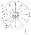
- a disc 2 of diameter 15 cm and thickness 0.5 cm is injection moulded from a plastics material.
- the disc 2 contains twelve equispaced capillary channels 4 extending radially through the body thereof. Each channel 4 is 10cm long, 300 ⁇ m wide and 60 ⁇ m deep.
- a first set of electrodes 6 and a second set of electrodes 8 are moulded into the disc 2 at the outer and inner ends respectively of the channels 4.
- a respective sample well 10 in the upper surface of the disc 2 communicates with each channel 4 adjacent its outer end electrode 6.
- a sample of the liquid whose chemical species are to be separated for analysis is introduced from a dispenser (not shown) into the well 10 at the outer end of one of the channels 4, and a high voltage, of 1500V, is applied between the electrodes 6 and 8 of that channel 4.
- the electric field causes the sample, or constituents thereof, to move towards the inner end of the channel 4, and in so doing the species separate along the channel 4 in accordance with their different mobilities.
- the strength of the electric field for a given length of channel 4 is chosen with respect to the liquid being sampled so that complete separation takes place before the sample reaches the inner end of the channel 4.
- the separated species of the liquid sample are detected at the inner end of the channel 4 by a pair of electrodes 12, which respond to the different electrical conductivities thereof.
- the species may then be treated separately, for example by electrical, electrochemical or optical analysis.
- the disc 2 is then rotated about its vertical axial shaft 14 so as to dispose the well 10 of the next channel 4 beneath the dispenser.
- the next sample is then dealt with as above.
- the second sample may be of the same liquid as, or different from, the first.
- the detector at the inner end of the second channel 4 may be the same as, or different from, that of the first.
- the analysis carried out on the second sample may be the same as, or different from, that carried out on the first.
- the disc 2 is successively rotated until a sample has been dealt with in each of the twelve channels 4.
- a disc 20 has twelve channels 22 that extend in curves between respective inner and outer electrodes 24 and 26, with respective sample inlets 28 located at the inner ends thereof. Such a path allows the channels 22 to have an increased length with respect to the linear paths of the channels 4 whilst maintaining the same disc diameter.
Landscapes
- Life Sciences & Earth Sciences (AREA)
- Health & Medical Sciences (AREA)
- Chemical & Material Sciences (AREA)
- Molecular Biology (AREA)
- Electrochemistry (AREA)
- Chemical Kinetics & Catalysis (AREA)
- Physics & Mathematics (AREA)
- Analytical Chemistry (AREA)
- Biochemistry (AREA)
- General Health & Medical Sciences (AREA)
- General Physics & Mathematics (AREA)
- Immunology (AREA)
- Pathology (AREA)
- Environmental & Geological Engineering (AREA)
- Engineering & Computer Science (AREA)
- Automatic Analysis And Handling Materials Therefor (AREA)
- Sampling And Sample Adjustment (AREA)
- Investigating Or Analyzing Materials By The Use Of Electric Means (AREA)
- Investigating Or Analysing Biological Materials (AREA)
Claims (15)
- Vorrichtung zum Trennen von mindestens zwei Flüssigkeiten in ihre Bestandteile durch Beaufschlagung mit einem elektrischen Feld; wobei die Vorrichtung aus einer Scheibe (2) besteht, die drehbar um eine im Wesentlichen zur Ebene der Scheibe rechtwinklig angeordnete Achse gehaltert ist, wobei die Scheibe mindestens zwei einzelne Kanäle (4) für flüssige Proben aufweist, worin das Verhältnis der Länge zum maximalen Quermaß jedes Kanals mindestens 100:1 beträgt, und worin jeder Kanal (a) einen Einlass (10) an einem Ende zur Aufnahme einer flüssigen Probe aufweist, (b) mindestens eine Elektrode (6, 8) an jedem Ende zur Beaufschlagung der Probe mit einem elektrischen Feld, wodurch eine Beförderung der Probe oder deren Bestandteile zum anderen Ende und eine Längsteilung in deren Bestandteile bewirkbar ist, und (c) Mittel (12) an dem anderen Ende zum Messen der getrennten Bestandteile der flüssigen Probe.
- Vorrichtung nach Anspruch 1, dadurch gekennzeichnet, dass die Kanäle (4) in der Dicke der Scheibe ausgebildet sind.
- Vorrichtung nach Anspruch 1 oder 2, dadurch gekennzeichnet, dass die Scheibe (2) aus zwei miteinander befestigten Platten ausgebildet ist.
- Vorrichtung nach einem der vorausgehenden Ansprüche, dadurch gekennzeichnet, dass sich mindestens ein und vorzugsweise jeder der Kanäle (4) zwischen dem Umfang und einem zentralen Bereich der Scheibe (2) erstreckt.
- Vorrichtung nach einem der vorausgehenden Ansprüche, dadurch gekennzeichnet, dass sich mindestens ein Kanal und vorzugsweise jeder der Kanäle (4) im Wesentlichen linear in der Ebene der Scheibe (2) erstreckt.
- Vorrichtung nach einem der vorausgehenden Ansprüche, dadurch gekennzeichnet, dass sich vorzugsweise jeder der Kanäle (4) in einer Serpentinenbahn in der Ebene der Scheibe (2) erstreckt.
- Vorrichtung nach einem der vorausgehenden Ansprüche, dadurch gekennzeichnet, dass das Maßverhältnis des Kanals (4) zwischen 200:1 und 500:1 beträgt.
- Vorrichtung nach einem der vorausgehenden Ansprüche, dadurch gekennzeichnet, dass jeder Kanal eine rechtwinklige Konfiguration aufweist.
- Vorrichtung nach einem der vorausgehenden Ansprüche, dadurch gekennzeichnet, dass das Messmittel die getrennten Komponenten elektrochemisch, elektrisch oder optisch misst.
- Vorrichtung nach einem der vorausgehenden Ansprüche, dadurch gekennzeichnet, dass Mittel an dem anderen Ende jedes Kanals zur Analyse der getrennten Bestandteile der Probe vorgesehen sind.
- Vorrichtung nach einem der vorausgehenden Ansprüche, dadurch gekennzeichnet, dass Mittel die Drehung der Scheibe derart bewirken, dass die Einlässe aufeinander folgender Kanäle einem Flüssigkeitsspender benachbart angeordnet sind.
- Verfahren zum Trennen einer Vielzahl flüssiger Proben in deren Bestandteile, worin eine Probe in einen Einlass an einem Ende eines Kanals einer Scheibe leitbar ist, wobei die Scheibe drehbar und eine weitere Probe in einen benachbarten Kanal einleitbar ist, Anlegen einer Spannung zwischen Elektroden an jedem Ende jedes Kanals derart, dass die Proben oder deren Bestandteile entlang ihrer jeweiligen Kanäle zu dem anderen Ende davon gelangen, und Messen der getrennten Bestandteile an den anderen Enden jedes der Kanäle, worin das Verhältnis der Länge zum größten Quermaß jedes Kanals mindestens 100:1 beträgt.
- Verfahren nach Anspruch 12, dadurch gekennzeichnet, dass die Scheibe mindestens drei der Kanäle aufweist und derart drehbar ist, dass aufeinander folgende flüssige Proben in benachbarte Kanäle einleitbar sind.
- Verfahren nach Anspruch 12 oder 13, dadurch gekennzeichnet, dass das Messen der Bestandteile jeder Probe elektrochemisch, elektrisch oder optisch erfolgt.
- Verfahren nach Anspruch 12 bis 14, dadurch gekennzeichnet, dass die getrennten Bestandteile analysiert werden.
Applications Claiming Priority (2)
| Application Number | Priority Date | Filing Date | Title |
|---|---|---|---|
| GB9802600 | 1998-02-07 | ||
| GBGB9802600.8A GB9802600D0 (en) | 1998-02-07 | 1998-02-07 | Liquid separation |
Publications (2)
| Publication Number | Publication Date |
|---|---|
| EP0934771A1 EP0934771A1 (de) | 1999-08-11 |
| EP0934771B1 true EP0934771B1 (de) | 2003-07-02 |
Family
ID=10826611
Family Applications (1)
| Application Number | Title | Priority Date | Filing Date |
|---|---|---|---|
| EP99200136A Expired - Lifetime EP0934771B1 (de) | 1998-02-07 | 1999-01-18 | Flüssigkeitstrennung |
Country Status (5)
| Country | Link |
|---|---|
| US (1) | US6132579A (de) |
| EP (1) | EP0934771B1 (de) |
| JP (1) | JPH11281619A (de) |
| DE (1) | DE69909148T2 (de) |
| GB (1) | GB9802600D0 (de) |
Families Citing this family (18)
| Publication number | Priority date | Publication date | Assignee | Title |
|---|---|---|---|---|
| AU773950B2 (en) * | 1999-07-16 | 2004-06-10 | Applera Corporation | High density electrophoresis device and method |
| US6428664B1 (en) | 2000-06-19 | 2002-08-06 | Roche Diagnostics Corporation | Biosensor |
| US7033475B2 (en) * | 2000-10-25 | 2006-04-25 | Shimadzu Corporation | Electrophoretic apparatus |
| US20020100714A1 (en) * | 2001-01-31 | 2002-08-01 | Sau Lan Tang Staats | Microfluidic devices |
| JP2003156475A (ja) * | 2001-11-22 | 2003-05-30 | Shimadzu Corp | チップ型電気泳動装置 |
| US6532997B1 (en) * | 2001-12-28 | 2003-03-18 | 3M Innovative Properties Company | Sample processing device with integral electrophoresis channels |
| US20050238506A1 (en) * | 2002-06-21 | 2005-10-27 | The Charles Stark Draper Laboratory, Inc. | Electromagnetically-actuated microfluidic flow regulators and related applications |
| US20060096906A1 (en) * | 2002-10-13 | 2006-05-11 | Adam Rubin | Microfluid biomolecule separation system |
| US7582261B2 (en) * | 2003-11-18 | 2009-09-01 | Sharp Kabuhsiki Kaisha | Electricity supplying device, electricity supplying apparatus, sample detection device, and sample detection apparatus |
| US7867194B2 (en) | 2004-01-29 | 2011-01-11 | The Charles Stark Draper Laboratory, Inc. | Drug delivery apparatus |
| WO2005072793A1 (en) | 2004-01-29 | 2005-08-11 | The Charles Stark Draper Laboratory, Inc. | Implantable drug delivery apparatus |
| WO2005089910A1 (en) * | 2004-03-17 | 2005-09-29 | Ciphergen Biosystems, Inc. | Multi-compartment filter and method of filtering using same |
| DE102006020035A1 (de) | 2006-04-26 | 2007-10-31 | B. Braun Melsungen Ag | Herstellung und Verwendung von Poly(hydroxyethylstärke)chitin- und Poly(Carboxymethylstärke)chitin-Verbindungen |
| US9046192B2 (en) | 2007-01-31 | 2015-06-02 | The Charles Stark Draper Laboratory, Inc. | Membrane-based fluid control in microfluidic devices |
| JP4831232B2 (ja) * | 2007-04-25 | 2011-12-07 | 株式会社島津製作所 | 電気泳動装置及び電気泳動方法 |
| CA2825757C (en) | 2011-02-02 | 2019-09-03 | The Charles Stark Draper Laboratory, Inc. | Drug delivery apparatus |
| EP3916090B1 (de) | 2016-01-29 | 2025-07-23 | Purigen Biosystems, Inc. | Isotachophorese zur reinigung von nukleinsäuren |
| SG11202000871WA (en) | 2017-08-02 | 2020-02-27 | Purigen Biosystems Inc | Systems, devices, and methods for isotachophoresis |
Family Cites Families (7)
| Publication number | Priority date | Publication date | Assignee | Title |
|---|---|---|---|---|
| US3956099A (en) * | 1972-10-30 | 1976-05-11 | Louis Israel | Continuous preparative electrophoresis apparatus |
| US4375401A (en) * | 1981-05-20 | 1983-03-01 | Nicholas Catsimpoolas | Electrophoresis system |
| CH655672B (de) * | 1984-02-22 | 1986-05-15 | ||
| US5413686A (en) * | 1992-07-17 | 1995-05-09 | Beckman Instruments, Inc. | Multi-channel automated capillary electrophoresis analyzer |
| EP0654090A4 (de) * | 1992-08-10 | 1998-07-08 | Biometric Imaging Inc | Analysenverfahren auf differentieller abtrennung beruhend und testkit. |
| US5585069A (en) * | 1994-11-10 | 1996-12-17 | David Sarnoff Research Center, Inc. | Partitioned microelectronic and fluidic device array for clinical diagnostics and chemical synthesis |
| US5872010A (en) * | 1995-07-21 | 1999-02-16 | Northeastern University | Microscale fluid handling system |
-
1998
- 1998-02-07 GB GBGB9802600.8A patent/GB9802600D0/en not_active Ceased
-
1999
- 1999-01-18 DE DE69909148T patent/DE69909148T2/de not_active Expired - Fee Related
- 1999-01-18 EP EP99200136A patent/EP0934771B1/de not_active Expired - Lifetime
- 1999-01-26 US US09/236,872 patent/US6132579A/en not_active Expired - Fee Related
- 1999-02-03 JP JP11026399A patent/JPH11281619A/ja active Pending
Also Published As
| Publication number | Publication date |
|---|---|
| DE69909148T2 (de) | 2004-04-22 |
| US6132579A (en) | 2000-10-17 |
| GB9802600D0 (en) | 1998-04-01 |
| EP0934771A1 (de) | 1999-08-11 |
| JPH11281619A (ja) | 1999-10-15 |
| DE69909148D1 (de) | 2003-08-07 |
Similar Documents
| Publication | Publication Date | Title |
|---|---|---|
| EP0934771B1 (de) | Flüssigkeitstrennung | |
| US7070682B2 (en) | Microfluidic apparatus for performing gel protein extractions and methods for using the apparatus | |
| US4631120A (en) | Method in which elemental particles electrophoretically migrate through a gel onto a collecting surface of a moving belt | |
| EP0776700B2 (de) | Verfahren zur Reinigung und Übertragung von sequenzierten DNA-Proben nach Trenn-/Feststellungssystem und Platte dafür | |
| EP1391723B1 (de) | Verfahren und Vorrichtung zum Analysieren eines Probenstoffgemisches | |
| US20070284250A1 (en) | Multifunctional Electrophoresis Cassette | |
| US20010027919A1 (en) | Electrophoresis analysis apparatus and sample vessel used therefor | |
| EP3226993B1 (de) | Vorrichtung und verfahren zur trennung von molekülen | |
| JPH10239278A (ja) | 電気泳動装置 | |
| US20110253535A1 (en) | Non-gel based two-dimensional protein separation multi-channel devices | |
| US5571398A (en) | Precise capillary electrophoretic interface for sample collection or analysis | |
| WO2017039080A1 (ko) | 샘플 농축 장치 및 이를 이용하여 농축된 샘플 추출 방법 | |
| WO2018182082A1 (ko) | 펌프가 필요 없는 비접촉식 전기전도도 측정 기반 미소유체 칩 등전점 전기영동 | |
| JPH0760145B2 (ja) | 試料中の成分検出装置 | |
| US4715943A (en) | Apparatus for separating a mixture of components by thin layer electrophoresis | |
| Inano et al. | Capillary isotachophoretic analysis of serum lipoproteins using a carrier ampholyte as spacer ion | |
| JPH11108889A (ja) | キャピラリー電気泳動装置 | |
| JP2000338086A (ja) | 電気泳動装置 | |
| JPS613041A (ja) | 核酸の塩基配列決定装置 | |
| GB2179564A (en) | Method of and apparatus for carrying out separation analysis investigations in a planar system | |
| JP3744310B2 (ja) | 電気泳動装置 | |
| JPS58198759A (ja) | 血中グルコ−スメ−タ | |
| US20070261961A1 (en) | Handling a plurality of samples | |
| EP0121936A2 (de) | Verbinder für einen für Ionenaktivität empfindlichen Fühler | |
| EP3128320A1 (de) | Trennmediumkassette zur probentrennungsadsorption und analysevorrichtung zur probentrennungsadsorption |
Legal Events
| Date | Code | Title | Description |
|---|---|---|---|
| PUAI | Public reference made under article 153(3) epc to a published international application that has entered the european phase |
Free format text: ORIGINAL CODE: 0009012 |
|
| AK | Designated contracting states |
Kind code of ref document: A1 Designated state(s): DE FR GB |
|
| AX | Request for extension of the european patent |
Free format text: AL;LT;LV;MK;RO;SI |
|
| 17P | Request for examination filed |
Effective date: 19991222 |
|
| AKX | Designation fees paid |
Free format text: DE FR GB |
|
| 17Q | First examination report despatched |
Effective date: 20020523 |
|
| GRAH | Despatch of communication of intention to grant a patent |
Free format text: ORIGINAL CODE: EPIDOS IGRA |
|
| GRAH | Despatch of communication of intention to grant a patent |
Free format text: ORIGINAL CODE: EPIDOS IGRA |
|
| GRAA | (expected) grant |
Free format text: ORIGINAL CODE: 0009210 |
|
| AK | Designated contracting states |
Designated state(s): DE FR GB |
|
| REG | Reference to a national code |
Ref country code: GB Ref legal event code: FG4D |
|
| REF | Corresponds to: |
Ref document number: 69909148 Country of ref document: DE Date of ref document: 20030807 Kind code of ref document: P |
|
| PGFP | Annual fee paid to national office [announced via postgrant information from national office to epo] |
Ref country code: GB Payment date: 20031211 Year of fee payment: 6 |
|
| PGFP | Annual fee paid to national office [announced via postgrant information from national office to epo] |
Ref country code: FR Payment date: 20040102 Year of fee payment: 6 |
|
| PGFP | Annual fee paid to national office [announced via postgrant information from national office to epo] |
Ref country code: DE Payment date: 20040130 Year of fee payment: 6 |
|
| ET | Fr: translation filed | ||
| PLBE | No opposition filed within time limit |
Free format text: ORIGINAL CODE: 0009261 |
|
| STAA | Information on the status of an ep patent application or granted ep patent |
Free format text: STATUS: NO OPPOSITION FILED WITHIN TIME LIMIT |
|
| 26N | No opposition filed |
Effective date: 20040405 |
|
| PG25 | Lapsed in a contracting state [announced via postgrant information from national office to epo] |
Ref country code: GB Free format text: LAPSE BECAUSE OF NON-PAYMENT OF DUE FEES Effective date: 20050118 |
|
| PG25 | Lapsed in a contracting state [announced via postgrant information from national office to epo] |
Ref country code: DE Free format text: LAPSE BECAUSE OF NON-PAYMENT OF DUE FEES Effective date: 20050802 |
|
| GBPC | Gb: european patent ceased through non-payment of renewal fee |
Effective date: 20050118 |
|
| PG25 | Lapsed in a contracting state [announced via postgrant information from national office to epo] |
Ref country code: FR Free format text: LAPSE BECAUSE OF NON-PAYMENT OF DUE FEES Effective date: 20050930 |
|
| REG | Reference to a national code |
Ref country code: FR Ref legal event code: ST |