EP0934826A1 - Méthode de mise en oeuvre d'une machine d'impression avec une pluralité des fonctions ainsi que dispositif de technique de commande - Google Patents
Méthode de mise en oeuvre d'une machine d'impression avec une pluralité des fonctions ainsi que dispositif de technique de commande Download PDFInfo
- Publication number
- EP0934826A1 EP0934826A1 EP99100863A EP99100863A EP0934826A1 EP 0934826 A1 EP0934826 A1 EP 0934826A1 EP 99100863 A EP99100863 A EP 99100863A EP 99100863 A EP99100863 A EP 99100863A EP 0934826 A1 EP0934826 A1 EP 0934826A1
- Authority
- EP
- European Patent Office
- Prior art keywords
- control
- parameters
- drive motor
- printing
- speed
- Prior art date
- Legal status (The legal status is an assumption and is not a legal conclusion. Google has not performed a legal analysis and makes no representation as to the accuracy of the status listed.)
- Granted
Links
- 238000007639 printing Methods 0.000 title claims abstract description 46
- 238000000034 method Methods 0.000 title claims abstract description 30
- 230000001133 acceleration Effects 0.000 claims abstract description 29
- 230000033001 locomotion Effects 0.000 claims description 11
- 230000008878 coupling Effects 0.000 claims description 8
- 238000010168 coupling process Methods 0.000 claims description 8
- 238000005859 coupling reaction Methods 0.000 claims description 8
- 238000005520 cutting process Methods 0.000 claims description 4
- 238000005516 engineering process Methods 0.000 claims description 4
- 125000004122 cyclic group Chemical group 0.000 claims description 2
- 238000003780 insertion Methods 0.000 claims 1
- 230000037431 insertion Effects 0.000 claims 1
- 238000012423 maintenance Methods 0.000 claims 1
- 238000013459 approach Methods 0.000 description 5
- 230000005540 biological transmission Effects 0.000 description 4
- 230000008859 change Effects 0.000 description 4
- 238000012545 processing Methods 0.000 description 3
- 238000011017 operating method Methods 0.000 description 2
- 238000012549 training Methods 0.000 description 2
- 238000007774 anilox coating Methods 0.000 description 1
- 230000015572 biosynthetic process Effects 0.000 description 1
- 238000004364 calculation method Methods 0.000 description 1
- 239000003086 colorant Substances 0.000 description 1
- 230000000694 effects Effects 0.000 description 1
- 230000002349 favourable effect Effects 0.000 description 1
- 238000004519 manufacturing process Methods 0.000 description 1
- 230000008569 process Effects 0.000 description 1
- 230000009467 reduction Effects 0.000 description 1
- 230000001105 regulatory effect Effects 0.000 description 1
- 238000003860 storage Methods 0.000 description 1
- 230000001360 synchronised effect Effects 0.000 description 1
- 238000003786 synthesis reaction Methods 0.000 description 1
Images



Classifications
-
- B—PERFORMING OPERATIONS; TRANSPORTING
- B41—PRINTING; LINING MACHINES; TYPEWRITERS; STAMPS
- B41F—PRINTING MACHINES OR PRESSES
- B41F13/00—Common details of rotary presses or machines
- B41F13/004—Electric or hydraulic features of drives
- B41F13/0045—Electric driving devices
Definitions
- the invention relates to a method for operating a printing press with a Most interacting in the functional and / or coupling network
- Printing machine parts that are moved by one or more drive motors, being used for coupling, coordination and / or synchronization of the movements one or more, commonly assigned to the printing press parts
- Guiding parameters position, speed and / or acceleration setpoints for the or a drive motor can be generated, whereupon the drive motor or motors to move the press part (s) in order to execute a or several printing functions can be controlled.
- the Invention a control or suitable for performing this method control arrangement, which has a computer-controlled drive system, which to control the multiple drive motors, one control unit each has at least one master control superordinate to this, which controls the Control units for the transmission of the control parameters is assigned.
- Printing press operating procedures and control engineering arrangements of this type are, for example, from the German Zeitschiff German printer "No. 18/8 May 1997, w30, w32, w34. Furthermore, in DE 195 27 199 A1 it is proposed in a flexographic printing machine that a guiding axis is imaged or generated in the control system, from the angular position setpoints and / or Angular position offset values for the anilox roller and / or the format cylinder of the inking units and / or for the counterpressure and / or central cylinders are derived. The electric motors assigned to these are to be controlled according to the setpoint or offset values.
- the leading axis depends on to map the output signals of the angular position sensor assigned to the central and / or impression cylinder and to influence only the inking units or any other impression cylinders with nominal position or offset values within the scope of the circumferential register adjustment as an electric motor - Generate back pressure or central cylinder t or is synthesized, and the angular position, setpoint and offset values of one, more or all of the rotation components derived from this master axis are impressed in parallel by an electric motor.
- the invention has for its object an operation and methodology for a To create printing press, which also has auxiliary functions previously provided by separately provided auxiliary drives were realized, are carried out by main drives can.
- the mode of operation should be structured in a clear and modular manner Software and can be carried out with a minimum of structural effort.
- the solution is for an operating method with the features mentioned at the beginning proposed according to the invention that to carry out the one or more printing functions or auxiliary functions for at least one of them responsible drive motor using a part of the setpoints or several travel parameters that the relevant printing (auxiliary) Functions correspond, are generated, and all from the control and Setpoint values obtained from each other to control the Drive motor are superimposed.
- the traversing parameters are superimposed in in relation to the guiding parameters and also with each other.
- the guide parameters expediently relate to the speed and / or acceleration, which is generally specified for the printing press or for its functional association with the relevant printing press parts.
- the guiding parameters can be a specification for a so-called virtual leading axis "or be implemented in this virtual master axis "forms the reference for the synchronization of a plurality of drive motors with printing machine parts moving therefrom, in particular rotating bodies such as rollers or cylinders.
- traversing block parameters are Speed and / or acceleration, the default being related to the Guiding parameters with absolute and / or relative register values.
- traversing block parameters are Speed and / or acceleration, the default being related to the Guiding parameters with absolute and / or relative register values.
- the travel parameters can be used, in particular, to set printing registers such as color / circumference and / or Cutting register of the printing press, a function and / or Coupling association thereof or the relevant press part for itself taken used. With you can also for register-correct coupling, Coordination and / or synchronization of the movements of the affected Drive motor are taken care of.
- sets of travel parameters can be used to implement additional changes in the angle of the respective drive motor in addition to machine parts coupled to it for rotation.
- the printing press or a functional association thereof according to the principle of individual drive technology known per se (cf. DE 41 38 479 A1, DE 43 22 744 A1, DE 195 27 199 A1, DE 195 29 430 A1, DE 196 33 745 A1, today's European Patent application Electrical drive system with distributed virtual master axis "from the same applicant under the attorney's file number B005 / 018 E EP), the additional angle changes of the respective individual drive compared to the so-called virtual master axis ", because this is where all setpoint and actual position values are related.
- a positive position setpoint causes an adjustment in the direction of the print Paper.
- a separate set of travel parameters can be used for the function of the Circumferential register, another separate set of travel parameters for the function of the cutting register. The following have for each traversing block Drive-specific parameters proven to be favorable: control word, mode, status, Travel offset, absolute travel, relative travel, absolute actual travel, target speed, Speed factor, minimum resulting speed, target acceleration.
- Setpoint generator which is a control module for the control parameters, a or several traversing block modules with the traversing parameters provided and has an overlay element connected downstream of these modules, whose output is assigned to the control unit, the modules mentioned for Implementation of their respective parameters in position, speed and / or Acceleration setpoints and for feeding them into the overlay element are trained.
- the one from the Superimposed result values contain compressed all information for setpoints to be entered in the downstream drive control units.
- the application flexibility is increased if after training the arrangement according to the invention the overlay member and the control unit Multiplier is interposed, which has multiple inputs, namely for the intermediate setpoint value or values output from the superimposition element and for one or more factors, for example one for a transmission over or Reduction certain gear factor.
- main and auxiliary functions of the printing press change dynamically or trigger auxiliary functions first. That will be with one Training of the arrangement according to the invention taken into account at least one of the traversing block modules on the input side with one or more externally accessible parameterization channels is provided. This can be done with the Master control or one or more control stands in connection.
- the control arrangement can be subdivided into a module level M, a processing level P and a controller level R.
- the levels are structured hierarchically in the order mentioned from top to bottom.
- a control module for recording parameters for printing press speed and printing press acceleration as well as a plurality of travel set modules V1-V5 for receiving travel parameters relating to absolute and / or relative position, speed and / or acceleration are arranged in module level M. All modules convert the recorded control and travel parameters into cyclically generated setpoints Y L , Y 1 -Y 5 for the position, speed and acceleration.
- the parameters Press speed "and Printing machine acceleration" represent specifications for a so-called virtual master axis, for which corresponding position, speed and acceleration setpoints are then generated in the setpoint generator or master value module.
- the three cyclical setpoints Y L , Y 1 -Y 5 per module L, V1 - V5 are fed to an overlay element ⁇ in processing level P, for example in the form of a summing point.
- a cyclic setpoint Y L , Y 1 -Y 5 from the modules L, V1 - V5 is superimposed with the result that an intermediate setpoint is output for the position, speed and / or acceleration of the relevant drive motor with driven machine part (s) becomes.
- These three intermediate setpoints Z L , Z G , Z B are also processed together, namely in a multiplier X. In addition to the three intermediate setpoint inputs Z L , Z G , Z B, this has a further input for an external factor F.
- the level of the setpoint generator S is left when the final setpoints E L , E G , E B are generated, and the individual setpoint / actual value comparators D L , D G , D B are supplied on the drive controller level R. At the same time, these comparators are given an actual value for the position, speed and acceleration, each with a negative sign.
- the control difference, which results from the position / actual value comparison D L is fed to a position controller with P behavior, which, in combination with a dimension factor, outputs a speed setpoint which, in addition to the final speed setpoint E G, the setpoint / actual value comparator D G is fed for speed.
- the actual value for the speed of the relevant drive motor or the driven machine part is entered with a negative sign.
- the setpoint / actual value comparator D G for the speed is followed by a speed controller with PI behavior, which also contains a dimension factor for converting the speed control difference into an acceleration.
- the acceleration resulting from the speed controller is overlaid with the final setpoint E B for acceleration from the setpoint generator S in the connected comparator D B. With this acceleration comparator, an actual value is not supplied.
- a transmission element with the mathematical relationship 1 / Ks is connected downstream of the acceleration comparator or superimposer D B. It outputs a current setpoint (generated from the acceleration / control difference received) to a subsequent setpoint / actual value comparator D I.
- the current comparator D I the current setpoint is compared with an actual current value (with a negative sign); the current control difference is fed to a downstream current controller with PI behavior. From its output, the current control value is converted into a control torque with respect to the drive motor or motors concerned by means of a further transmission element K T.
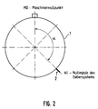
- FIG 2 is the arrangement of the coordinate systems for both the machine functional components as well as for the assigned sensor or encoder systems shown schematically.
- Functional components mostly rotary body 1, and the sensors rotary encoder 2.
- the angle ⁇ being determined and for the later operation is to be saved.
- the angle ⁇ indicates how much the rotating body 1 is to be moved out of its basic position until the angle encoder 2 receives a signal for the achievement of its absolute zero.
- the corresponding data will be Appropriately in the assigned drive unit with an electric motor and digital Drive controller saved.
- the reference point approach is for all printing unit and folding unit drives perform. It is the first time that the drive system has been commissioned for the whole machine to take place. After each exchange of the sensor or Encoder system, components of the encoder system or changes in the The reference point approach must be repeated in the machine coordinate system.
- a first sequence step 31 the rotating body 1, for example a rubber cylinder, is mechanically locked.
- the operating mode of the drive unit for the reference point approach is parameterized by a superordinate master control.
- this sets the current target operating mode.
- step 34 for example, a digital signal processor of the drive controller in the drive unit reads the current position of the rotating body 1 and invalidates a load-related modulo position.
- step 35 the parameter Order status "is set, with the drive unit reporting to the master control that its requirement has been met.
- the locking of the rotating body 1 is removed.
- the higher-level master control signals the release of the drive to the drive unit in the following step 38 the parameter Order status ".
- the higher-level master control of the drive unit has specified a setpoint speed with the value zero.
- the actual setpoint speed for the reference point setpoint is determined independently by the parameterization of a traversing block specific to this. The same applies to the setpoint acceleration. Because of the use of traversing blocks is based on today's European patent applications Electric drive system with a distributed, virtual master axis "(legal code B005 / 018 P DE) and Referencing procedure for a machine or system "(attorney's code B005 / 019 P DE) by the same applicant, filed on the same filing date.
- the traversing block is now automatically converted into traversing movements for the rotating body by the digital signal processor of the drive unit
- the traversing movements serve to trigger the encoder zero pulse in order to determine the angle ⁇ according to Figure 2. If this is successfully done within two revolutions, the
- the next calibration sequence step 392 is the internal calculation and storage of the position of the encoder zero pulse by the digital signal processor of the drive unit, followed by an acknowledgment of the order to the higher-level control system in sequence step 393, whereby the parameter Order status "is set again.
- the higher-level master control then transmits the command in sequence step 394 Lock the drive unit ".
- the drive motor is set to a desired one Move the target position by, for example, a further basic movement Motion is superimposed according to a specific travel parameter.
- a such positioning can e.g. be used for the plate change.
- a specific set of travel parameters from the control center or control system Parameterization channels 3 (see FIG. 1) parameterized accordingly.
- From the master control a target speed with zero can be specified via master parameters.
- The can actually set speed and acceleration of the positioning process define themselves through the assigned traversing block.
- the parameterization of the Target speed and target acceleration for the relevant traversing block determined during commissioning and in the drive system or in the controller R des affected drive motor stored. The implementation of the positioning will appropriately commissioned by the master control system.
- step 41 the current target operating mode is set by the master control. Then the drive (drive controller R and drive motor) is released from the master control - cf. Sequence step 42.
- the control system reads the current, load-related actual position in the degree unit.
- the absolute target position is parameterized by the master control (if necessary via parameterization channels 3 - see FIG. 1) in the degree unit.
- the desired target position is introduced, which depends on the actual position of the drive.
- branching step 45 it is examined whether a permissible value range for the actual position related to the load is not exceeded. If exceeded, the drive positions would not be related to the machine coordinate system.
- the drive must therefore carry out a basic position run (cf. European patent application today Referencing procedure ... "by the same applicant - attorney's code B005 / 019 E EP).
- the basic position travel is carried out independently at the level of the setpoint generator S or controller R, in accordance with sequence step 46.
- sequence step 47 the drive then moves to the setpoint position, followed by the sequence step 48 the message Job completed "to the master control.
- the drive is then blocked according to sequence step 49.
Landscapes
- Engineering & Computer Science (AREA)
- Mechanical Engineering (AREA)
- Inking, Control Or Cleaning Of Printing Machines (AREA)
- Character Spaces And Line Spaces In Printers (AREA)
- Control Of Multiple Motors (AREA)
- Control Of Presses (AREA)
- Rotary Presses (AREA)
Applications Claiming Priority (2)
| Application Number | Priority Date | Filing Date | Title |
|---|---|---|---|
| DE19801756 | 1998-01-20 | ||
| DE19801756 | 1998-01-20 |
Publications (2)
| Publication Number | Publication Date |
|---|---|
| EP0934826A1 true EP0934826A1 (fr) | 1999-08-11 |
| EP0934826B1 EP0934826B1 (fr) | 2001-05-16 |
Family
ID=7854997
Family Applications (1)
| Application Number | Title | Priority Date | Filing Date |
|---|---|---|---|
| EP99100863A Expired - Lifetime EP0934826B1 (fr) | 1998-01-20 | 1999-01-19 | Méthode de mise en oeuvre d'une machine d'impression avec une pluralité des fonctions ainsi que dispositif de technique de commande |
Country Status (4)
| Country | Link |
|---|---|
| EP (1) | EP0934826B1 (fr) |
| AT (1) | ATE201165T1 (fr) |
| DE (1) | DE59900090D1 (fr) |
| ES (1) | ES2156452T3 (fr) |
Cited By (4)
| Publication number | Priority date | Publication date | Assignee | Title |
|---|---|---|---|---|
| DE10243454A1 (de) * | 2002-09-19 | 2004-04-01 | Koenig & Bauer Ag | Antriebsvorrichtung |
| DE102004048315A1 (de) * | 2004-10-05 | 2006-04-06 | Man Roland Druckmaschinen Ag | Druckeinheit einer Druckmaschine und Verfahren zur Durchführung eines Druckplattenwechsels an einem Formzylinder einer Druckeinheit |
| EP1719618A1 (fr) * | 2005-05-07 | 2006-11-08 | Koenig & Bauer AG | Procédé pour déterminer de façon reproductible la position angulaire spatiale d'au moins un cylindre d'une machine d'impression, dispositif pour la réalisation du procédé et machine d'impression. |
| DE102005042563A1 (de) * | 2005-09-08 | 2007-03-15 | Man Roland Druckmaschinen Ag | Druckmaschine |
Citations (4)
| Publication number | Priority date | Publication date | Assignee | Title |
|---|---|---|---|---|
| DE4322744A1 (de) * | 1993-07-08 | 1995-01-19 | Baumueller Nuernberg Gmbh | Elektrisches Antriebssystem zur Verstellung von einem oder mehreren dreh- und/oder verschwenkbaren Funktionsteilen in Geräten und Maschinen, Antriebsanordnung mit einem Winkellagegeber und Druckmaschine |
| EP0709184A1 (fr) * | 1994-09-29 | 1996-05-01 | MAN Roland Druckmaschinen AG | Procédé pour signaler des différences de repère |
| DE19527199A1 (de) * | 1995-07-26 | 1997-01-30 | Baumueller Nuernberg Gmbh | Flexodruckmaschine und deren Verwendung |
| WO1998016384A1 (fr) * | 1996-10-12 | 1998-04-23 | Goss Graphic Systems Limited | Appareil d'impression |
-
1999
- 1999-01-19 AT AT99100863T patent/ATE201165T1/de active
- 1999-01-19 ES ES99100863T patent/ES2156452T3/es not_active Expired - Lifetime
- 1999-01-19 EP EP99100863A patent/EP0934826B1/fr not_active Expired - Lifetime
- 1999-01-19 DE DE59900090T patent/DE59900090D1/de not_active Expired - Lifetime
Patent Citations (4)
| Publication number | Priority date | Publication date | Assignee | Title |
|---|---|---|---|---|
| DE4322744A1 (de) * | 1993-07-08 | 1995-01-19 | Baumueller Nuernberg Gmbh | Elektrisches Antriebssystem zur Verstellung von einem oder mehreren dreh- und/oder verschwenkbaren Funktionsteilen in Geräten und Maschinen, Antriebsanordnung mit einem Winkellagegeber und Druckmaschine |
| EP0709184A1 (fr) * | 1994-09-29 | 1996-05-01 | MAN Roland Druckmaschinen AG | Procédé pour signaler des différences de repère |
| DE19527199A1 (de) * | 1995-07-26 | 1997-01-30 | Baumueller Nuernberg Gmbh | Flexodruckmaschine und deren Verwendung |
| WO1998016384A1 (fr) * | 1996-10-12 | 1998-04-23 | Goss Graphic Systems Limited | Appareil d'impression |
Cited By (12)
| Publication number | Priority date | Publication date | Assignee | Title |
|---|---|---|---|---|
| DE10243454A1 (de) * | 2002-09-19 | 2004-04-01 | Koenig & Bauer Ag | Antriebsvorrichtung |
| DE10243454B4 (de) * | 2002-09-19 | 2005-01-20 | Koenig & Bauer Ag | Antriebsvorrichtung einer Bearbeitungsmaschine |
| EP1563994A1 (fr) * | 2002-09-19 | 2005-08-17 | Koenig & Bauer Aktiengesellschaft | Procédé d'entraínement d'une machine de traitement |
| EP1563993A1 (fr) * | 2002-09-19 | 2005-08-17 | Koenig & Bauer Aktiengesellschaft | Dispositivs d'entraínement et procédé d'entraínement d'une machine de traitement |
| US7448321B2 (en) | 2002-09-19 | 2008-11-11 | Koenig & Bauer Aktiengesellschaft | Drive devices and method for driving a processing machine |
| DE10243454C5 (de) * | 2002-09-19 | 2009-10-08 | Koenig & Bauer Aktiengesellschaft | Antriebsvorrichtung einer Bearbeitungsmaschine |
| US7712415B2 (en) | 2002-09-19 | 2010-05-11 | Koenig & Bauer Aktiengesellschaft | Drive devices and method for driving a processing machine |
| DE102004048315A1 (de) * | 2004-10-05 | 2006-04-06 | Man Roland Druckmaschinen Ag | Druckeinheit einer Druckmaschine und Verfahren zur Durchführung eines Druckplattenwechsels an einem Formzylinder einer Druckeinheit |
| US7497163B2 (en) | 2004-10-05 | 2009-03-03 | Man Roland Druckmaschinen Ag | Printing unit of a printing press and method for carrying out a printing-plate change on a forme cylinder of a printing unit |
| EP1719618A1 (fr) * | 2005-05-07 | 2006-11-08 | Koenig & Bauer AG | Procédé pour déterminer de façon reproductible la position angulaire spatiale d'au moins un cylindre d'une machine d'impression, dispositif pour la réalisation du procédé et machine d'impression. |
| EP1759840A1 (fr) * | 2005-05-07 | 2007-03-07 | Koenig & Bauer Aktiengesellschaft | Procédé pour déterminer de façon reproductible la position angulaire spatiale d'au moins un cylindre d'une machine d'impression, dispositif pour la réalisation du procédé et machine d'impression |
| DE102005042563A1 (de) * | 2005-09-08 | 2007-03-15 | Man Roland Druckmaschinen Ag | Druckmaschine |
Also Published As
| Publication number | Publication date |
|---|---|
| ATE201165T1 (de) | 2001-06-15 |
| ES2156452T3 (es) | 2001-06-16 |
| DE59900090D1 (de) | 2001-06-21 |
| EP0934826B1 (fr) | 2001-05-16 |
Similar Documents
| Publication | Publication Date | Title |
|---|---|---|
| DE10243454C5 (de) | Antriebsvorrichtung einer Bearbeitungsmaschine | |
| EP0904934B1 (fr) | Dispositif et procédé d'entraínement des machines d'impression avec plussieurs moteurs indépendents | |
| EP0812682B1 (fr) | Entraínement pour une machine à imprimer | |
| EP0852538B1 (fr) | Presse rotative sans arbre | |
| DE4137979B4 (de) | Antrieb für eine Druckmaschine mit mindestens zwei mechanisch voneinander entkoppelten Druckwerken | |
| EP1493564A1 (fr) | Machine d'impression offset | |
| DE19903869B4 (de) | Verfahren zur Antriebssteuerung von Bogendruckmaschinen | |
| DE102013209698A1 (de) | Druckwerk einer Druckmaschine | |
| DE102011118904A1 (de) | Produktionswerk mit Einzelantrieb | |
| EP0709184B1 (fr) | Dispositif pour éviter des défauts de repérage | |
| EP1373992B1 (fr) | Procede pour faire fonctionner de maniere synchronisee des machines presentant des arbres entraines par des organes d'entrainement individuels | |
| EP1531992B1 (fr) | Dispositif d'entrainement et procede pour assurer la commande d'une unite d'imprimante | |
| EP0934826B1 (fr) | Méthode de mise en oeuvre d'une machine d'impression avec une pluralité des fonctions ainsi que dispositif de technique de commande | |
| DE10259494B4 (de) | Verfahren zum Steuern einer Druckmaschine | |
| DE19961880B4 (de) | Elektrisches Antriebssystem zur aktiven Schwingungsdämpfung | |
| EP0692377B1 (fr) | Procédé et dispositif pour l'entraínement synchrone de composants d'une machine d'impression | |
| DE102016201747A1 (de) | Verfahren zum registergenauen Bearbeiten einer Bahn | |
| DE102007020727A1 (de) | Druckmaschine und Verfahren zum Betreiben einer Druckmaschine | |
| EP0930158A1 (fr) | Procédé pour établir des références dans une machine ou installation | |
| DE102005021148B3 (de) | Verfahren zur Regelung eines Umfangsregisters in einer Druckmaschine | |
| DE10212534B4 (de) | Verfahren zum Antreiben einer Druckmaschine | |
| EP2748003B1 (fr) | Procédé permettant de déterminer chaque position d'au moins une surface d'impression sur une bande de matériau sur laquelle au moins une image doit être imprimée dans une machine d'impression | |
| DE4316261B4 (de) | Mehrmotorenantrieb für eine Bogen-Offset-Rotationsdruckmaschine | |
| EP2243630B1 (fr) | Imprimante rotative dotée d'une synchronisation du groupe d'entraînement du pliage | |
| EP1149697A2 (fr) | Méthode et dispositif de fonctionnement d'une machine d'impression avec deux entraínements individuels |
Legal Events
| Date | Code | Title | Description |
|---|---|---|---|
| PUAI | Public reference made under article 153(3) epc to a published international application that has entered the european phase |
Free format text: ORIGINAL CODE: 0009012 |
|
| AK | Designated contracting states |
Kind code of ref document: A1 Designated state(s): AT BE CH CY DE DK ES FI FR GB GR IE IT LI LU MC NL PT SE |
|
| AX | Request for extension of the european patent |
Free format text: AL;LT;LV;MK;RO;SI |
|
| 17P | Request for examination filed |
Effective date: 19990708 |
|
| 17Q | First examination report despatched |
Effective date: 19991110 |
|
| AKX | Designation fees paid |
Free format text: AT BE CH CY DE DK ES FI FR GB GR IE IT LI LU MC NL PT SE |
|
| GRAG | Despatch of communication of intention to grant |
Free format text: ORIGINAL CODE: EPIDOS AGRA |
|
| GRAG | Despatch of communication of intention to grant |
Free format text: ORIGINAL CODE: EPIDOS AGRA |
|
| GRAH | Despatch of communication of intention to grant a patent |
Free format text: ORIGINAL CODE: EPIDOS IGRA |
|
| GRAH | Despatch of communication of intention to grant a patent |
Free format text: ORIGINAL CODE: EPIDOS IGRA |
|
| GRAA | (expected) grant |
Free format text: ORIGINAL CODE: 0009210 |
|
| AK | Designated contracting states |
Kind code of ref document: B1 Designated state(s): AT BE CH CY DE DK ES FI FR GB GR IE IT LI LU MC NL PT SE |
|
| PG25 | Lapsed in a contracting state [announced via postgrant information from national office to epo] |
Ref country code: IE Free format text: LAPSE BECAUSE OF FAILURE TO SUBMIT A TRANSLATION OF THE DESCRIPTION OR TO PAY THE FEE WITHIN THE PRESCRIBED TIME-LIMIT Effective date: 20010516 |
|
| REF | Corresponds to: |
Ref document number: 201165 Country of ref document: AT Date of ref document: 20010615 Kind code of ref document: T |
|
| REG | Reference to a national code |
Ref country code: CH Ref legal event code: NV Representative=s name: ISLER & PEDRAZZINI AG Ref country code: CH Ref legal event code: EP |
|
| REG | Reference to a national code |
Ref country code: IE Ref legal event code: FG4D Free format text: GERMAN |
|
| REG | Reference to a national code |
Ref country code: ES Ref legal event code: FG2A Ref document number: 2156452 Country of ref document: ES Kind code of ref document: T3 |
|
| REF | Corresponds to: |
Ref document number: 59900090 Country of ref document: DE Date of ref document: 20010621 |
|
| ITF | It: translation for a ep patent filed | ||
| PG25 | Lapsed in a contracting state [announced via postgrant information from national office to epo] |
Ref country code: PT Free format text: LAPSE BECAUSE OF FAILURE TO SUBMIT A TRANSLATION OF THE DESCRIPTION OR TO PAY THE FEE WITHIN THE PRESCRIBED TIME-LIMIT Effective date: 20010816 Ref country code: DK Free format text: LAPSE BECAUSE OF FAILURE TO SUBMIT A TRANSLATION OF THE DESCRIPTION OR TO PAY THE FEE WITHIN THE PRESCRIBED TIME-LIMIT Effective date: 20010816 |
|
| PG25 | Lapsed in a contracting state [announced via postgrant information from national office to epo] |
Ref country code: GR Free format text: LAPSE BECAUSE OF FAILURE TO SUBMIT A TRANSLATION OF THE DESCRIPTION OR TO PAY THE FEE WITHIN THE PRESCRIBED TIME-LIMIT Effective date: 20010817 |
|
| GBT | Gb: translation of ep patent filed (gb section 77(6)(a)/1977) |
Effective date: 20010808 |
|
| ET | Fr: translation filed | ||
| REG | Reference to a national code |
Ref country code: GB Ref legal event code: IF02 |
|
| PGFP | Annual fee paid to national office [announced via postgrant information from national office to epo] |
Ref country code: ES Payment date: 20020103 Year of fee payment: 4 |
|
| PG25 | Lapsed in a contracting state [announced via postgrant information from national office to epo] |
Ref country code: LU Free format text: LAPSE BECAUSE OF NON-PAYMENT OF DUE FEES Effective date: 20020119 |
|
| PG25 | Lapsed in a contracting state [announced via postgrant information from national office to epo] |
Ref country code: CY Free format text: LAPSE BECAUSE OF FAILURE TO SUBMIT A TRANSLATION OF THE DESCRIPTION OR TO PAY THE FEE WITHIN THE PRESCRIBED TIME-LIMIT Effective date: 20020131 Ref country code: BE Free format text: LAPSE BECAUSE OF NON-PAYMENT OF DUE FEES Effective date: 20020131 |
|
| REG | Reference to a national code |
Ref country code: IE Ref legal event code: FD4D |
|
| PGFP | Annual fee paid to national office [announced via postgrant information from national office to epo] |
Ref country code: FI Payment date: 20020305 Year of fee payment: 4 |
|
| PLBE | No opposition filed within time limit |
Free format text: ORIGINAL CODE: 0009261 |
|
| STAA | Information on the status of an ep patent application or granted ep patent |
Free format text: STATUS: NO OPPOSITION FILED WITHIN TIME LIMIT |
|
| 26N | No opposition filed | ||
| BERE | Be: lapsed |
Owner name: BAUMULLER ANLAGEN-SYSTEMTECHNIK G.M.B.H. & CO. Effective date: 20020131 |
|
| PG25 | Lapsed in a contracting state [announced via postgrant information from national office to epo] |
Ref country code: MC Free format text: LAPSE BECAUSE OF NON-PAYMENT OF DUE FEES Effective date: 20020801 |
|
| PG25 | Lapsed in a contracting state [announced via postgrant information from national office to epo] |
Ref country code: FI Free format text: LAPSE BECAUSE OF NON-PAYMENT OF DUE FEES Effective date: 20030119 |
|
| PG25 | Lapsed in a contracting state [announced via postgrant information from national office to epo] |
Ref country code: ES Free format text: LAPSE BECAUSE OF NON-PAYMENT OF DUE FEES Effective date: 20030120 |
|
| PG25 | Lapsed in a contracting state [announced via postgrant information from national office to epo] |
Ref country code: NL Free format text: LAPSE BECAUSE OF NON-PAYMENT OF DUE FEES Effective date: 20030801 |
|
| NLV4 | Nl: lapsed or anulled due to non-payment of the annual fee |
Effective date: 20030801 |
|
| REG | Reference to a national code |
Ref country code: ES Ref legal event code: FD2A Effective date: 20030120 |
|
| PG25 | Lapsed in a contracting state [announced via postgrant information from national office to epo] |
Ref country code: IT Free format text: LAPSE BECAUSE OF NON-PAYMENT OF DUE FEES;WARNING: LAPSES OF ITALIAN PATENTS WITH EFFECTIVE DATE BEFORE 2007 MAY HAVE OCCURRED AT ANY TIME BEFORE 2007. THE CORRECT EFFECTIVE DATE MAY BE DIFFERENT FROM THE ONE RECORDED. Effective date: 20050119 |
|
| PGFP | Annual fee paid to national office [announced via postgrant information from national office to epo] |
Ref country code: SE Payment date: 20050119 Year of fee payment: 7 |
|
| PG25 | Lapsed in a contracting state [announced via postgrant information from national office to epo] |
Ref country code: SE Free format text: LAPSE BECAUSE OF NON-PAYMENT OF DUE FEES Effective date: 20060120 |
|
| EUG | Se: european patent has lapsed | ||
| REG | Reference to a national code |
Ref country code: CH Ref legal event code: PCAR Free format text: ISLER & PEDRAZZINI AG;POSTFACH 1772;8027 ZUERICH (CH) |
|
| PGRI | Patent reinstated in contracting state [announced from national office to epo] |
Ref country code: IT Effective date: 20091001 |
|
| PGFP | Annual fee paid to national office [announced via postgrant information from national office to epo] |
Ref country code: CH Payment date: 20130123 Year of fee payment: 15 Ref country code: FR Payment date: 20130207 Year of fee payment: 15 Ref country code: GB Payment date: 20130122 Year of fee payment: 15 |
|
| PGFP | Annual fee paid to national office [announced via postgrant information from national office to epo] |
Ref country code: AT Payment date: 20130121 Year of fee payment: 15 |
|
| PGFP | Annual fee paid to national office [announced via postgrant information from national office to epo] |
Ref country code: IT Payment date: 20140128 Year of fee payment: 16 |
|
| REG | Reference to a national code |
Ref country code: CH Ref legal event code: PL |
|
| REG | Reference to a national code |
Ref country code: AT Ref legal event code: MM01 Ref document number: 201165 Country of ref document: AT Kind code of ref document: T Effective date: 20140119 |
|
| GBPC | Gb: european patent ceased through non-payment of renewal fee |
Effective date: 20140119 |
|
| PG25 | Lapsed in a contracting state [announced via postgrant information from national office to epo] |
Ref country code: LI Free format text: LAPSE BECAUSE OF NON-PAYMENT OF DUE FEES Effective date: 20140131 Ref country code: CH Free format text: LAPSE BECAUSE OF NON-PAYMENT OF DUE FEES Effective date: 20140131 |
|
| REG | Reference to a national code |
Ref country code: FR Ref legal event code: ST Effective date: 20140930 |
|
| PG25 | Lapsed in a contracting state [announced via postgrant information from national office to epo] |
Ref country code: FR Free format text: LAPSE BECAUSE OF NON-PAYMENT OF DUE FEES Effective date: 20140131 Ref country code: AT Free format text: LAPSE BECAUSE OF NON-PAYMENT OF DUE FEES Effective date: 20140119 Ref country code: GB Free format text: LAPSE BECAUSE OF NON-PAYMENT OF DUE FEES Effective date: 20140119 |
|
| PG25 | Lapsed in a contracting state [announced via postgrant information from national office to epo] |
Ref country code: IT Free format text: LAPSE BECAUSE OF NON-PAYMENT OF DUE FEES Effective date: 20150119 |
|
| PGFP | Annual fee paid to national office [announced via postgrant information from national office to epo] |
Ref country code: DE Payment date: 20170125 Year of fee payment: 19 |
|
| REG | Reference to a national code |
Ref country code: DE Ref legal event code: R119 Ref document number: 59900090 Country of ref document: DE |
|
| PG25 | Lapsed in a contracting state [announced via postgrant information from national office to epo] |
Ref country code: DE Free format text: LAPSE BECAUSE OF NON-PAYMENT OF DUE FEES Effective date: 20180801 |