EP0935331B1 - Kommutator mit verbesserten segmentverbindungen - Google Patents
Kommutator mit verbesserten segmentverbindungen Download PDFInfo
- Publication number
- EP0935331B1 EP0935331B1 EP98938930A EP98938930A EP0935331B1 EP 0935331 B1 EP0935331 B1 EP 0935331B1 EP 98938930 A EP98938930 A EP 98938930A EP 98938930 A EP98938930 A EP 98938930A EP 0935331 B1 EP0935331 B1 EP 0935331B1
- Authority
- EP
- European Patent Office
- Prior art keywords
- carbon
- segments
- commutator
- brazing material
- conductive members
- Prior art date
- Legal status (The legal status is an assumption and is not a legal conclusion. Google has not performed a legal analysis and makes no representation as to the accuracy of the status listed.)
- Expired - Lifetime
Links
- OKTJSMMVPCPJKN-UHFFFAOYSA-N Carbon Chemical compound [C] OKTJSMMVPCPJKN-UHFFFAOYSA-N 0.000 claims description 121
- 229910052799 carbon Inorganic materials 0.000 claims description 119
- 238000005219 brazing Methods 0.000 claims description 61
- 239000000463 material Substances 0.000 claims description 47
- 239000011347 resin Substances 0.000 claims description 31
- 229920005989 resin Polymers 0.000 claims description 31
- 239000000758 substrate Substances 0.000 claims description 29
- PXHVJJICTQNCMI-UHFFFAOYSA-N Nickel Chemical compound [Ni] PXHVJJICTQNCMI-UHFFFAOYSA-N 0.000 claims description 18
- 239000000446 fuel Substances 0.000 claims description 17
- VYZAMTAEIAYCRO-UHFFFAOYSA-N Chromium Chemical compound [Cr] VYZAMTAEIAYCRO-UHFFFAOYSA-N 0.000 claims description 13
- 229910052804 chromium Inorganic materials 0.000 claims description 13
- 239000011651 chromium Substances 0.000 claims description 13
- RYGMFSIKBFXOCR-UHFFFAOYSA-N Copper Chemical compound [Cu] RYGMFSIKBFXOCR-UHFFFAOYSA-N 0.000 claims description 11
- 229910052802 copper Inorganic materials 0.000 claims description 11
- 239000010949 copper Substances 0.000 claims description 11
- 238000002844 melting Methods 0.000 claims description 11
- 230000008018 melting Effects 0.000 claims description 11
- 229910052759 nickel Inorganic materials 0.000 claims description 9
- 238000010304 firing Methods 0.000 claims description 8
- 238000004519 manufacturing process Methods 0.000 claims description 7
- 210000000078 claw Anatomy 0.000 description 11
- 238000005336 cracking Methods 0.000 description 7
- 238000005476 soldering Methods 0.000 description 7
- 238000003466 welding Methods 0.000 description 6
- 238000005452 bending Methods 0.000 description 5
- 238000004873 anchoring Methods 0.000 description 4
- 230000003247 decreasing effect Effects 0.000 description 4
- 230000000717 retained effect Effects 0.000 description 4
- 229910000881 Cu alloy Inorganic materials 0.000 description 3
- 239000004020 conductor Substances 0.000 description 3
- 238000010276 construction Methods 0.000 description 3
- 239000002828 fuel tank Substances 0.000 description 3
- 238000000034 method Methods 0.000 description 3
- 229910000679 solder Inorganic materials 0.000 description 3
- 230000007423 decrease Effects 0.000 description 2
- 230000002950 deficient Effects 0.000 description 2
- QSHDDOUJBYECFT-UHFFFAOYSA-N mercury Chemical compound [Hg] QSHDDOUJBYECFT-UHFFFAOYSA-N 0.000 description 2
- 229910052753 mercury Inorganic materials 0.000 description 2
- 238000007747 plating Methods 0.000 description 2
- LFQSCWFLJHTTHZ-UHFFFAOYSA-N Ethanol Chemical compound CCO LFQSCWFLJHTTHZ-UHFFFAOYSA-N 0.000 description 1
- 239000003575 carbonaceous material Substances 0.000 description 1
- 239000000470 constituent Substances 0.000 description 1
- 238000001816 cooling Methods 0.000 description 1
- 230000006866 deterioration Effects 0.000 description 1
- 230000002542 deteriorative effect Effects 0.000 description 1
- LTMHDMANZUZIPE-PUGKRICDSA-N digoxin Chemical compound C1[C@H](O)[C@H](O)[C@@H](C)O[C@H]1O[C@@H]1[C@@H](C)O[C@@H](O[C@@H]2[C@H](O[C@@H](O[C@@H]3C[C@@H]4[C@]([C@@H]5[C@H]([C@]6(CC[C@@H]([C@@]6(C)[C@H](O)C5)C=5COC(=O)C=5)O)CC4)(C)CC3)C[C@@H]2O)C)C[C@@H]1O LTMHDMANZUZIPE-PUGKRICDSA-N 0.000 description 1
- 230000003292 diminished effect Effects 0.000 description 1
- 238000009434 installation Methods 0.000 description 1
- 238000011835 investigation Methods 0.000 description 1
- 239000000155 melt Substances 0.000 description 1
- 229910052751 metal Inorganic materials 0.000 description 1
- 239000002184 metal Substances 0.000 description 1
- 238000000465 moulding Methods 0.000 description 1
- 238000004080 punching Methods 0.000 description 1
- 229910052709 silver Inorganic materials 0.000 description 1
- 239000004332 silver Substances 0.000 description 1
Images


Classifications
-
- H—ELECTRICITY
- H02—GENERATION; CONVERSION OR DISTRIBUTION OF ELECTRIC POWER
- H02K—DYNAMO-ELECTRIC MACHINES
- H02K13/00—Structural associations of current collectors with motors or generators, e.g. brush mounting plates or connections to windings; Disposition of current collectors in motors or generators; Arrangements for improving commutation
-
- H—ELECTRICITY
- H01—ELECTRIC ELEMENTS
- H01R—ELECTRICALLY-CONDUCTIVE CONNECTIONS; STRUCTURAL ASSOCIATIONS OF A PLURALITY OF MUTUALLY-INSULATED ELECTRICAL CONNECTING ELEMENTS; COUPLING DEVICES; CURRENT COLLECTORS
- H01R39/00—Rotary current collectors, distributors or interrupters
- H01R39/02—Details for dynamo electric machines
- H01R39/32—Connections of conductor to commutator segment
-
- H—ELECTRICITY
- H01—ELECTRIC ELEMENTS
- H01R—ELECTRICALLY-CONDUCTIVE CONNECTIONS; STRUCTURAL ASSOCIATIONS OF A PLURALITY OF MUTUALLY-INSULATED ELECTRICAL CONNECTING ELEMENTS; COUPLING DEVICES; CURRENT COLLECTORS
- H01R39/00—Rotary current collectors, distributors or interrupters
- H01R39/02—Details for dynamo electric machines
- H01R39/04—Commutators
- H01R39/06—Commutators other than with external cylindrical contact surface, e.g. flat commutators
-
- H—ELECTRICITY
- H01—ELECTRIC ELEMENTS
- H01R—ELECTRICALLY-CONDUCTIVE CONNECTIONS; STRUCTURAL ASSOCIATIONS OF A PLURALITY OF MUTUALLY-INSULATED ELECTRICAL CONNECTING ELEMENTS; COUPLING DEVICES; CURRENT COLLECTORS
- H01R43/00—Apparatus or processes specially adapted for manufacturing, assembling, maintaining, or repairing of line connectors or current collectors or for joining electric conductors
- H01R43/06—Manufacture of commutators
- H01R43/08—Manufacture of commutators in which segments are not separated until after assembly
-
- H—ELECTRICITY
- H01—ELECTRIC ELEMENTS
- H01R—ELECTRICALLY-CONDUCTIVE CONNECTIONS; STRUCTURAL ASSOCIATIONS OF A PLURALITY OF MUTUALLY-INSULATED ELECTRICAL CONNECTING ELEMENTS; COUPLING DEVICES; CURRENT COLLECTORS
- H01R43/00—Apparatus or processes specially adapted for manufacturing, assembling, maintaining, or repairing of line connectors or current collectors or for joining electric conductors
- H01R43/02—Apparatus or processes specially adapted for manufacturing, assembling, maintaining, or repairing of line connectors or current collectors or for joining electric conductors for soldered or welded connections
-
- Y—GENERAL TAGGING OF NEW TECHNOLOGICAL DEVELOPMENTS; GENERAL TAGGING OF CROSS-SECTIONAL TECHNOLOGIES SPANNING OVER SEVERAL SECTIONS OF THE IPC; TECHNICAL SUBJECTS COVERED BY FORMER USPC CROSS-REFERENCE ART COLLECTIONS [XRACs] AND DIGESTS
- Y10—TECHNICAL SUBJECTS COVERED BY FORMER USPC
- Y10T—TECHNICAL SUBJECTS COVERED BY FORMER US CLASSIFICATION
- Y10T29/00—Metal working
- Y10T29/49—Method of mechanical manufacture
- Y10T29/49002—Electrical device making
- Y10T29/49009—Dynamoelectric machine
- Y10T29/49011—Commutator or slip ring assembly
Definitions
- Each of the segments 31 is formed by compressing and molding carbon powder and by thermally treating the segments 31. Further, a hook 33 that connects a coil of an armature 7 is formed on the conductive members 32.
- the resin-made substrate 30 is formed at the center of the axis of rotation of the segments 31.
- Each of the segments 31 and conductive members 32 are insulated from other segments 31 and conductive members 32 by slits 34 formed in the radial direction.
- a method for producing such a commutator made of carbon is disclosed in U.S. Patent No. 5,175,463 .
- the surface of a ring-like carbon member having a parallel surface is first treated so that a metallic ring may be joined thereto.
- This metallic ring is made of a conductive material, such as copper, and is attached to the surface of the ring-like carbon member by soldering.
- the commutator is filled with resin to form a resin substrate that supports the carbon member and the metallic ring.
- Slits 34 are then formed in the carbon member and the metallic ring in the radial direction in order to divide the carbon member and the metallic ring into sections, so that the segments 31 and the conductive members 32 are formed.
- an armature (rotor) coil is connected to the conductive member 32 by soldering or welding.
- FIG. 1 shows one example of an electro-drive type fuel pump of in-tank system that is provided in a fuel tank.
- the motor cover 4 includes a brush 13, which can slidingly contact the commutators 12 of the armature 7, and a spring 14 that biases the brush 13.
- the brush 13 is connected to an external connection terminal via a choke coil 15.
- a fuel supply pipe is connected to a check valve 17 that is incorporated in a discharge port 16 and is secured to the motor cover 4.
- a pump body 18 is attached to the lower end part of the housing 3 by caulking.
- a fuel inlet port 19 is provided in the pump body 18.
- a fuel outlet port 20 is provided in the pump cover 5.
- a disk-shaped impeller 21 having a number of blade grooves 22 formed in the circumferential direction is disposed in the pump chamber formed by the pump body 18 and the pump cover 5. The impeller 21 is fitted onto and connected to the armature shaft 8.
- the impeller 21 is driven and rotated by supplying an electric current to the motor section 1, which rotates the axis of the armature 7.
- fuel in the fuel tank is suctioned through the inlet port 19 and is supplied to the motor chamber 6 through the outlet port 20, so that the fuel is discharged from the discharge port 16 into a fuel supply pipe.
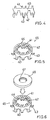
- a conductive metallic plate is punched and has a body section 40, claws (retaining members) 41 and 42 to retain a resin substrate, and a hook 43 for connecting to a coil.
- a metallic plate is used that is made of copper or a copper alloy having a higher conductivity.
- the body section 40 of the metallic plate is then curled into a cylindrical shape.
- Metallic ring 45 is formed by folding the claws 41 and 42 towards the center of the cylindrical body section and by folding the hook 43 outward thereof. If the metallic plate is made of copper or a copper alloy, the curling of the body section 40 and the folding of the claws 41 and 42 is further improved.
- a disk-shaped carbon member 46 is formed from carbon powder that is compressed molded and heat-treated and is joined to the metallic ring 45 by brazing.
- the melting point of the brazing material should be higher than the temperature that the brazing material reaches from the heat absorbed when connecting the coil to the conductive member. If the melting point of the brazing material is higher than the soldering or welding temperature (for example, approx. 1,000 C), this condition is satisfied. Therefore, a brazing material containing nickel and chromium is according to the present invention as the brazing material to join the carbon member 46 and the metallic rings 45.
- the thermal expansion coefficient of the carbon member 46 is different from the thermal expansion coefficient of the brazing material, cracks, etc., are likely to form in the carbon member 46 when the brazing material cools.
- the difference in the thermal expansion coefficient between chromium used in the brazing material and the carbon member 46 is small (i.e., the thermal expansion coefficient of chromium is 8.4 x 10 -6 /C, and the thermal expansion coefficient of carbon is 7 x 10 -6 / C)
- stress in the carbon member 46 which results from a difference in the thermal expansion efficient between the carbon material 46 and the brazing material, is insignificant as the brazing material cools after the brazing step is completed. Therefore, it is possible to prevent the carbon member 46 from cracking, etc., when the brazing material cools.
- brazing temperature is less than the melting point of the metallic rings 45.
- a brazing material JIS Z 3265 BNi-7 (Japanese Industrial Standards) containing chromium, of which the major constituent is nickel, was used as brazing material because it satisfies the above-mentioned conditions.
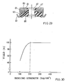
- FIG. 30 shows a correlation between the bending strength of the carbon member and the yield of commutators if brazing is performed with a brazing material containing nickel and chromium. As shown in FIG. 30 , if the bending strength of the carbon member is less than 200 kg/cm 2 , the yield decreases. Therefore, the carbon member preferably has a bending strength of 200 kg/cm 2 or more.
- the firing temperature of the carbon member 46 is preferably higher than the brazing temperature.
- carbon having a firing temperature that is higher than the melting point of a brazing material is used.
- a brazing material having a lower melting point than the firing temperature of the carbon member is used.
- the brazing surface area of the carbon member 46 is small, because the end face of the metallic rings 45, i.e., the plate thickness face 44, is brazed.
- stress in the carbon member 46 which may be generated by a difference in the thermal expansion coefficients of carbon member 46 and the brazing material when the brazing material cools, is reduced, and it is possible to prevent cracks, etc., from forming in carbon member 46.
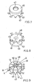
- slits 50 are formed at the carbon members 46 and the metallic rings 45 in the radial direction, so that they are insulated from each other.
- a coil is connected to the hook 43 of the conductive members 52 by soldering, welding, etc. Because the conductive members 52 are formed of a metallic plate made of copper or copper alloy, the thermal conductivity is good, and the coil can be easily connected by welding.
- the resistance of the carbon members 46 can be reduced, thereby reducing power loss. Still further, it is possible to prevent cracks, etc., from forming in the carbon members 46 as a result of the heat applied to the carbon member when the carbon members 46 are brazed.
- the number of retaining members (claws 41 and 42) for retaining the resin substrate and installation place thereof may be appropriately changed, and the retaining members may be omitted.
- the shape of the retaining members (claws 41 and 42) may modified in various ways. For example, as shown in FIG. 12 , retaining members 55 having a C-shaped cross section may be used.
- the supporting member is not limited to a resin substrate in order to support the segments (carbon members) and the conductive members (metallic rings). The shape, position, etc., of the stepped portion 47 formed on the carbon members 46 may be appropriately modified, and indeed the stepped portion 47 may be omitted.
- a construction may be utilized that facilitates the positioning of the carbon members 46 and the metallic rings 45.
- a tapered section 56 may be formed, by which the carbon members 46 and the metallic rings 45 can be attached at a position opposed to each other.
- the carbon members 46 and the metallic rings 45 may be brazed together after positioning at the tapered section 56.
- a groove 57 is formed in the carbon members 46. After the end face of the metallic ring 45 is inserted into the groove 57, and the carbon members 46 and the metallic rings 45 are positioned, the engaging portions may be brazed.
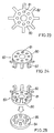
- the second preferred embodiment differs from the first embodiment only in the shapes of the metallic rings and the carbon members.
- the metallic rings 64 and disk-shaped carbon members 65 are brazed together using a brazing material.
- a base 66 and a fitting portion 67 are formed at the carbon members 65.
- the metallic rings 64 and the carbon members 65 are filled with resin, thus forming a resin substrate 68.
- a fitting hole 69 is opened, and the armature axis 8 is fitted inside along the center of rotational axis of the resin substrate 68.
- a stepped portion 47 which is similar to that in the first preferred embodiment, is formed in the carbon members 65.
- slits 70 are then formed in the carbon members 65 and the metallic rings 64 in the radial direction, so as to insulate each other and to form a plurality of radially disposed and generally fan-shaped segments 71 and a plurality of conductive members 72 joined to the respective segments 71.
- Hooks 62 of the conductive members 71 are folded outward, and a coil is connected to hooks 62.
- FIG. 21 shows a cross-sectional view taken along the line XXI-XXI in FIG. 20
- FIG. 22 shows a cross-sectional view taken along the line that XXII-XXII in FIG. 21 .
- the third preferred embodiment differs from the first and second preferred embodiments only in the shape of the metallic ring and the carbon member.
- a conductive metallic plate is punched and has a ring-like body section 80, a hole 81, and a hook 82. As shown in FIG. 24 , the hook 82 is folded outward to form a metallic ring 83.
- the metallic ring 83 and a disk-shaped carbon member 84 are brazed together using a brazing material containing chromium and nickel, so that a protrusion part 85 is formed on the carbon members 84.
- a brazing material containing chromium and nickel By inserting the protrusions 85 of the carbon member 84 into the holes 81 in the metallic ring 83, the carbon member 84 and the metallic ring 83 can be easily positioned.
- the hole 81 and the protrusions 85 are brazed together.
- the end face of the metallic ring 83 to be brazed i.e., the circumferential surface of the hole 81, is as small as possible.
- the metallic ring 83 and the carbon member 84 are filled with resin in order to form a resin substrate 86.
- a fitting hole 87 is formed, into which the armature axis 8 is fitted along the center of rotational axis of the resin substrate 86.
- a stepped portion 47 is formed, as in the first preferred embodiment, so that the metallic ring 83 is firmly retained in the resin substrate 86 by the protrusions 85 of the carbon member 84.
- the protrusions 85 protrude from the hole 81 of the metallic ring 83 while the carbon member 65 is firmly retained at the resin substrate 86 by the anchoring part of the resin substrate, which is formed in the stepped portion 47.
- FIG. 28 shows a cross-sectional view taken along the line XXIX-XXIX in FIG. 28 .
- the shape of the metallic ring and the carbon member, the structure of the brazing portions of the metallic ring and the carbon member, and method thereof, etc. may be modified in various ways.
- the bonding strength between the carbon member (segments) and the metallic ring (conductive members) is not reduced, because the brazing material does not melt from the heat applied to the brazing material when connecting a coil to the conductive members.
- a metallic film, such as plating is not required to be formed on the carbon member, fabrication is simplified and costs can be reduced.
- the difference in the thermal expansion coefficients between the brazing material and the carbon member is small, the carbon member can be prevented from cracking, etc., as a result of stress generated after the brazing is finished and as the brazing material cools.
- the metallic ring is configured so that the brazing surface area of the carbon member is reduced, the carbon member can be prevented from cracking from stress when the brazing material cools. Further, because the metallic plate having the metallic ring can be produced by punching, the production is simplified and costs thereof is reduced. Further, because a resin substrate is formed after the carbon member and the metallic ring are adhered together, the firing temperature of the carbon member can be increased. Thus, because the resistance of the carbon member can be decreased, power loss can be reduced. As a result, the carbon member can be further prevented from cracking, etc., from the heat when the carbon member 46 is brazed.
- a commutator according to the invention is useful, not only for an electro-drive type fuel pump of in-tank system, but is also useful for rotating machines such as motors, generators and dynamos in a variety of fields.
Landscapes
- Engineering & Computer Science (AREA)
- Manufacturing & Machinery (AREA)
- Power Engineering (AREA)
- Motor Or Generator Current Collectors (AREA)
- Manufacturing Of Electrical Connectors (AREA)
Claims (7)
- Kommutator, der aus Kohlenstoff gebildete Segmente (51; 71; 89), leitende Elemente (52; 72; 90), die aus Kupfer hergestellt sind, mit denen eine Spule verbunden werden soll, und ein Trägerelement (48; 68; 86), das die Segmente und die leitenden Elemente hält, umfasst, wobei die Segmente mit einem Lotmaterial an die leitenden Elemente gelötet sind, wobei das Lotmaterial einen Schmelzpunkt aufweist, der höher ist als die Temperatur, die zum Verbinden der Spule mit den leitenden Elementen (52; 72; 90) eingesetzt wird, dadurch gekennzeichnet, dass das Lotmaterial Nickel und Chrom enthält.
- Kommutator nach Anspruch 1, bei dem die Segmente (51; 71; 89) aus einem Material gebildet sind, das eine Brenntemperatur aufweist, die höher ist als die Löttemperatur.
- Kommutator nach Anspruch 1, bei dem die Löttemperatur niedriger ist als der Schmelzpunkt der leitenden Elemente (52; 72; 90).
- Kommutator nach einem der Ansprüche 1 bis 3, bei dem Haken (43; 62; 82) zum Verbinden einer Spule integriert mit den leitenden Elementen (52; 72; 90) geformt sind.
- Kommutator nach Anspruch 4, bei dem das Trägerelement (48; 68; 86) aus Harz gebildet ist und bei dem ein Halteelement (41, 42; 63) zum Halten des Trägerelements integriert mit den leitenden Elementen (52; 72; 90) geformt ist.
- Verwendung eines Kommutators nach einem der Ansprüche 1 bis 5 in einer Kraftstoffpumpe des elektrisch angetriebenen Typs.
- Verfahren zur Herstellung eines Kommutators, der aus Kohlenstoff gebildete Segmente (51; 71; 89), leitende Elemente (52; 72; 90), die aus Kupfer hergestellt sind, mit denen eine Spule verbunden werden soll, und ein Trägerelement (48; 68; 86), das die Segmente und die leitenden Elemente hält, aufweist, umfassend die Schritte:Löten eines Metallrings (45; 64; 83), der Kupfer umfasst, und eines Kohlenstoffelements (46; 65; 84) mit einem Lotmaterial, wobei das Lotmaterial einen Schmelzpunkt aufweist, der höher ist als die Temperatur, die zum Verbinden der Spule mit den leitenden Elementen (52; 72; 90) eingesetzt wird,Bilden eines Harzsubstrats (48; 68; 86) auf dem Metallring und dem Kohlenstoffelement, undBilden von Segmenten (51; 71; 89) und leitenden Elementen (52; 72; 90) durch Herstellen von Schlitzen (50; 70; 88) auf dem Metallring und dem Kohlenstoffelement, dadurch gekennzeichnet, dass das Lotmaterial Nickel und Chrom enthält.
Applications Claiming Priority (3)
| Application Number | Priority Date | Filing Date | Title |
|---|---|---|---|
| JP22509097 | 1997-08-21 | ||
| JP22509097 | 1997-08-21 | ||
| PCT/JP1998/003710 WO1999010968A1 (en) | 1997-08-21 | 1998-08-21 | Commutateur of improved segment joinability |
Publications (3)
| Publication Number | Publication Date |
|---|---|
| EP0935331A1 EP0935331A1 (de) | 1999-08-11 |
| EP0935331A4 EP0935331A4 (de) | 2005-06-08 |
| EP0935331B1 true EP0935331B1 (de) | 2008-06-11 |
Family
ID=16823852
Family Applications (1)
| Application Number | Title | Priority Date | Filing Date |
|---|---|---|---|
| EP98938930A Expired - Lifetime EP0935331B1 (de) | 1997-08-21 | 1998-08-21 | Kommutator mit verbesserten segmentverbindungen |
Country Status (6)
| Country | Link |
|---|---|
| US (1) | US6392325B2 (de) |
| EP (1) | EP0935331B1 (de) |
| JP (1) | JP3425962B2 (de) |
| KR (1) | KR100346605B1 (de) |
| DE (1) | DE69839598D1 (de) |
| WO (1) | WO1999010968A1 (de) |
Families Citing this family (15)
| Publication number | Priority date | Publication date | Assignee | Title |
|---|---|---|---|---|
| KR100278006B1 (ko) * | 1998-11-11 | 2001-01-15 | 윤종용 | 정류자를 구비한 전자렌지, 및 전자렌지용 정류자의 제조방법 |
| MXPA05006707A (es) * | 2000-05-31 | 2005-09-08 | Kolektor Group Doo | Conmutador plano. |
| DE10115601C1 (de) * | 2001-03-29 | 2002-09-05 | Kolektor D O O | Trommelkommutator sowie Verfahren zu seiner Herstellung |
| JP2002305858A (ja) * | 2001-03-30 | 2002-10-18 | Kyosan Denki Co Ltd | 車両用モータ式燃料ポンプ |
| JP2004229352A (ja) * | 2003-01-20 | 2004-08-12 | Denso Corp | 回転電機の電機子及びこの電機子を有するスタータ |
| DE102004034434B4 (de) * | 2004-07-16 | 2006-08-03 | Kolektor Group D.O.O. | Verfahren zur Herstellung eines Plankommutators sowie Leiterrohling für einen Plankommutator |
| JP4600744B2 (ja) * | 2004-10-20 | 2010-12-15 | 日立化成工業株式会社 | カーボン整流子の製造法 |
| DE102005041499A1 (de) * | 2005-09-01 | 2007-03-08 | Temic Automotive Electric Motors Gmbh | Kommutator für eine elektrische Maschine |
| DE102006046670A1 (de) * | 2006-09-29 | 2008-04-03 | Robert Bosch Gmbh | Kommutator für eine elektrische Maschine |
| DE102006046666A1 (de) * | 2006-09-29 | 2008-04-03 | Robert Bosch Gmbh | Plankommutator |
| CN100491038C (zh) * | 2006-10-08 | 2009-05-27 | 浙江长城换向器有限公司 | 碳换向器的焊接工艺 |
| GB0800464D0 (en) * | 2008-01-11 | 2008-02-20 | Johnson Electric Sa | Improvement in or relating to a commutator |
| JP6327346B2 (ja) * | 2014-06-20 | 2018-05-23 | 株式会社村田製作所 | 回転機 |
| CN108723652B (zh) * | 2018-06-06 | 2020-06-02 | 成都中超碳素科技有限公司 | 一种机械密封组件的焊装工艺方法 |
| CN120824994B (zh) * | 2025-09-18 | 2025-12-05 | 瑞安市韩田汽车工业有限公司 | 一种汽车风扇电机及控制电路 |
Family Cites Families (20)
| Publication number | Priority date | Publication date | Assignee | Title |
|---|---|---|---|---|
| JPS5846059B2 (ja) * | 1977-04-15 | 1983-10-14 | 株式会社日立製作所 | 半導体装置 |
| DE3023108C2 (de) * | 1979-07-02 | 1986-04-24 | Aupac K.K., Tokio/Tokyo | Verfahren zum Herstellen eines Kommutators |
| ATE23080T1 (de) * | 1983-06-03 | 1986-11-15 | Bbc Brown Boveri & Cie | Kollektor fuer eine elektrische maschine und verfahren zu dessen herstellung. |
| DE3855544T2 (de) * | 1987-04-10 | 1997-03-27 | Hitachi Ltd | Keramische Verbundwerkstoff und Verfahren zur Herstellung desselben |
| US5316987A (en) * | 1987-04-10 | 1994-05-31 | Hitachi, Ltd. | Ceramic composite and process for production thereof |
| JPH0226880A (ja) | 1988-07-15 | 1990-01-29 | Demutetsuku Kk | 黒鉛と金属のロー付け方法 |
| US5175463A (en) | 1989-08-07 | 1992-12-29 | Kirkwood Industries | Carbon commutator |
| US5400496A (en) | 1990-07-13 | 1995-03-28 | Robert Bosch Gmbh | Method of making a planar collector |
| DE9010542U1 (de) * | 1990-07-13 | 1991-11-07 | Robert Bosch Gmbh, 7000 Stuttgart | Plankollektor |
| DE4028420A1 (de) * | 1990-09-07 | 1992-03-12 | Kautt & Bux Kg | Plankommutator und verfahren zu seiner herstellung |
| JP2651963B2 (ja) * | 1991-07-17 | 1997-09-10 | 純一 高崎 | 回転子およびその製造方法 |
| JP3313509B2 (ja) * | 1994-04-25 | 2002-08-12 | 株式会社ミツバ | コミテータ |
| JP2883545B2 (ja) | 1994-08-22 | 1999-04-19 | オーパック株式会社 | 扁平型整流子およびその製造方法 |
| FR2734669B1 (fr) * | 1995-05-22 | 1997-06-20 | Le Carbonne Lorraine | Bagues d'alternateurs et collecteurs cylindriques en materiau composite cupro-graphitique fritee |
| DE19525584A1 (de) * | 1995-07-13 | 1997-01-16 | Kautt & Bux Commutator Gmbh | Verfahren zur Herstellung eines Plankommutators |
| JP3613872B2 (ja) * | 1995-09-26 | 2005-01-26 | 株式会社デンソー | 燃料供給装置およびその製造方法 |
| US5793140A (en) * | 1995-12-19 | 1998-08-11 | Walbro Corporation | Electric motor flat commutator |
| US5925961A (en) * | 1996-04-05 | 1999-07-20 | Sugiyama Seisakusyo Co., Ltd. | Plane carbon commutator and its manufacturing method |
| KR19980068127A (ko) * | 1997-02-15 | 1998-10-15 | 김광호 | 납땜용 무연 합금 |
| US5932949A (en) * | 1997-10-03 | 1999-08-03 | Mccord Winn Textron Inc. | Carbon commutator |
-
1998
- 1998-08-21 EP EP98938930A patent/EP0935331B1/de not_active Expired - Lifetime
- 1998-08-21 WO PCT/JP1998/003710 patent/WO1999010968A1/ja not_active Ceased
- 1998-08-21 DE DE69839598T patent/DE69839598D1/de not_active Expired - Fee Related
- 1998-08-21 US US09/284,467 patent/US6392325B2/en not_active Expired - Fee Related
- 1998-08-21 JP JP51416999A patent/JP3425962B2/ja not_active Expired - Fee Related
- 1998-08-21 KR KR1019997003417A patent/KR100346605B1/ko not_active Expired - Fee Related
Also Published As
| Publication number | Publication date |
|---|---|
| KR100346605B1 (ko) | 2002-07-26 |
| DE69839598D1 (de) | 2008-07-24 |
| US6392325B2 (en) | 2002-05-21 |
| US20010013737A1 (en) | 2001-08-16 |
| EP0935331A1 (de) | 1999-08-11 |
| JP3425962B2 (ja) | 2003-07-14 |
| KR20000068793A (ko) | 2000-11-25 |
| EP0935331A4 (de) | 2005-06-08 |
| WO1999010968A1 (en) | 1999-03-04 |
Similar Documents
| Publication | Publication Date | Title |
|---|---|---|
| EP0935331B1 (de) | Kommutator mit verbesserten segmentverbindungen | |
| US5793140A (en) | Electric motor flat commutator | |
| US6160337A (en) | Electric motor with carbon track commutator | |
| JP2002514038A (ja) | カーボン整流子 | |
| US5826324A (en) | Method of manufacturing flat-type commutator | |
| JP4596404B2 (ja) | 燃料ポンプ用直流電動機の通電部材とその製造方法および燃料ポンプ | |
| JPWO1999010968A1 (ja) | セグメントの接合性を改善したコンミュテータ | |
| US20100107401A1 (en) | Method of manufacturing motor | |
| US6114791A (en) | Commutator for motor using amorphous carbon and fuel pump unit using the same | |
| JPH07298559A (ja) | コミテータ | |
| US5012149A (en) | Assembled commutator for an electric motor | |
| JP3613872B2 (ja) | 燃料供給装置およびその製造方法 | |
| JPH08308183A (ja) | カーボン整流子 | |
| JP3972352B2 (ja) | 整流子およびそれを用いた燃料ポンプ | |
| US20050248224A1 (en) | Flat-type vibration motor | |
| US6242839B1 (en) | Commutator and method for manufacturing | |
| US6611077B2 (en) | Motor having a commutator | |
| KR20000048240A (ko) | 평면 정류자를 구비한 전기 모터용 전기자 | |
| US20050151441A1 (en) | Commutator, and electrical motor and fluid pump using the same | |
| KR100302636B1 (ko) | 비정질탄소를사용하는모터용정류자와이정류자를사용하는연료펌프장치 | |
| JP4132114B2 (ja) | 整流子およびそれを用いた燃料ポンプ | |
| JP3919050B2 (ja) | 整流子、それを用いた燃料ポンプおよび整流子の製造方法 | |
| JP3154560B2 (ja) | 回転電機の回転子及びその製造方法 | |
| JP4105024B2 (ja) | 直流電動機及びこの直流電動機を用いた燃料ポンプ | |
| JP2000208224A (ja) | 整流子およびそれを用いた燃料ポンプ |
Legal Events
| Date | Code | Title | Description |
|---|---|---|---|
| PUAI | Public reference made under article 153(3) epc to a published international application that has entered the european phase |
Free format text: ORIGINAL CODE: 0009012 |
|
| 17P | Request for examination filed |
Effective date: 19990421 |
|
| AK | Designated contracting states |
Kind code of ref document: A1 Designated state(s): DE IT |
|
| RAP1 | Party data changed (applicant data changed or rights of an application transferred) |
Owner name: HARADA MANUFACTURING CO. LTD Owner name: AISAN KOGYO KABUSHIKI KAISHA |
|
| A4 | Supplementary search report drawn up and despatched |
Effective date: 20050426 |
|
| RIC1 | Information provided on ipc code assigned before grant |
Ipc: 7H 01R 39/04 B Ipc: 7H 01R 43/08 B Ipc: 7H 01R 39/06 B Ipc: 7H 02K 13/00 A |
|
| 17Q | First examination report despatched |
Effective date: 20051115 |
|
| GRAP | Despatch of communication of intention to grant a patent |
Free format text: ORIGINAL CODE: EPIDOSNIGR1 |
|
| RTI1 | Title (correction) |
Free format text: COMMUTATOR OF IMPROVED SEGMENT JOINABILITY |
|
| GRAS | Grant fee paid |
Free format text: ORIGINAL CODE: EPIDOSNIGR3 |
|
| GRAA | (expected) grant |
Free format text: ORIGINAL CODE: 0009210 |
|
| AK | Designated contracting states |
Kind code of ref document: B1 Designated state(s): DE IT |
|
| RAP2 | Party data changed (patent owner data changed or rights of a patent transferred) |
Owner name: AISAN KOGYO KABUSHIKI KAISHA |
|
| REF | Corresponds to: |
Ref document number: 69839598 Country of ref document: DE Date of ref document: 20080724 Kind code of ref document: P |
|
| PGFP | Annual fee paid to national office [announced via postgrant information from national office to epo] |
Ref country code: DE Payment date: 20080826 Year of fee payment: 11 |
|
| PLBE | No opposition filed within time limit |
Free format text: ORIGINAL CODE: 0009261 |
|
| STAA | Information on the status of an ep patent application or granted ep patent |
Free format text: STATUS: NO OPPOSITION FILED WITHIN TIME LIMIT |
|
| 26N | No opposition filed |
Effective date: 20090312 |
|
| PG25 | Lapsed in a contracting state [announced via postgrant information from national office to epo] |
Ref country code: IT Free format text: LAPSE BECAUSE OF FAILURE TO SUBMIT A TRANSLATION OF THE DESCRIPTION OR TO PAY THE FEE WITHIN THE PRESCRIBED TIME-LIMIT Effective date: 20080611 |
|
| PG25 | Lapsed in a contracting state [announced via postgrant information from national office to epo] |
Ref country code: DE Free format text: LAPSE BECAUSE OF NON-PAYMENT OF DUE FEES Effective date: 20100302 |