EP0935396A2 - Appareil et méthode de codage vidéo - Google Patents
Appareil et méthode de codage vidéo Download PDFInfo
- Publication number
- EP0935396A2 EP0935396A2 EP99101689A EP99101689A EP0935396A2 EP 0935396 A2 EP0935396 A2 EP 0935396A2 EP 99101689 A EP99101689 A EP 99101689A EP 99101689 A EP99101689 A EP 99101689A EP 0935396 A2 EP0935396 A2 EP 0935396A2
- Authority
- EP
- European Patent Office
- Prior art keywords
- blocks
- group
- refresh
- coding
- frame
- Prior art date
- Legal status (The legal status is an assumption and is not a legal conclusion. Google has not performed a legal analysis and makes no representation as to the accuracy of the status listed.)
- Withdrawn
Links
Images














Classifications
-
- H—ELECTRICITY
- H04—ELECTRIC COMMUNICATION TECHNIQUE
- H04N—PICTORIAL COMMUNICATION, e.g. TELEVISION
- H04N19/00—Methods or arrangements for coding, decoding, compressing or decompressing digital video signals
- H04N19/60—Methods or arrangements for coding, decoding, compressing or decompressing digital video signals using transform coding
- H04N19/61—Methods or arrangements for coding, decoding, compressing or decompressing digital video signals using transform coding in combination with predictive coding
-
- H—ELECTRICITY
- H04—ELECTRIC COMMUNICATION TECHNIQUE
- H04N—PICTORIAL COMMUNICATION, e.g. TELEVISION
- H04N19/00—Methods or arrangements for coding, decoding, compressing or decompressing digital video signals
- H04N19/50—Methods or arrangements for coding, decoding, compressing or decompressing digital video signals using predictive coding
- H04N19/503—Methods or arrangements for coding, decoding, compressing or decompressing digital video signals using predictive coding involving temporal prediction
-
- H—ELECTRICITY
- H04—ELECTRIC COMMUNICATION TECHNIQUE
- H04N—PICTORIAL COMMUNICATION, e.g. TELEVISION
- H04N19/00—Methods or arrangements for coding, decoding, compressing or decompressing digital video signals
- H04N19/10—Methods or arrangements for coding, decoding, compressing or decompressing digital video signals using adaptive coding
- H04N19/102—Methods or arrangements for coding, decoding, compressing or decompressing digital video signals using adaptive coding characterised by the element, parameter or selection affected or controlled by the adaptive coding
- H04N19/103—Selection of coding mode or of prediction mode
- H04N19/107—Selection of coding mode or of prediction mode between spatial and temporal predictive coding, e.g. picture refresh
Definitions
- the present invention relates to a video coding apparatus and a video coding method for compression-coding a video signal in high efficiency and transmitting the same, and more particularly, it relates to refresh of video coding for eliminating influence caused by a transmission error in a reproduced picture.
- FIG. 34A As the field of application of the technique of compression coding a video signal in high efficiency and transmitting the same, a visual telephone or a video conference shown in FIG. 34A is general. Further, application to a system shown in FIG. 34B for transmitting a video signal through digital radio communication utilizing a transmission path of wireless LAN for monitoring a danger point or transmitting a picture between mobiles, and application to picture distribution utilizing Internet shown in FIG. 34C are expected.
- the wireless monitoring is indispensable to compression-code the picture signal in high efficiency for efficiently utilizing the frequency band in view of effective use of wireless resources, and the communication quality represented by the error rate lowers by at least two or three digits as compared with a cable system. Therefore, the wireless monitoring is readily influenced by an error when performing high-efficiency compression coding omitting redundant information, and hence it is indispensable to improve error resistance by devising a refresh method or the like as described later.
- transmission of picture information is generally unidirectional from a camera side to a monitor side in the case of monitoring, and the range of utilization rather widens when the refresh functions through a unidirectional transmission path.
- a portable visual telephone employing digital radio communication such as PHS (Personal Handyphone System) is also assumed.
- PHS Personal Handyphone System
- a bidirectional transmission path can be ensured although the quality is inferior as compared with the cable system.
- the Internet network presupposes the best effort, there is no guarantee on the quality of a packet waste rate or the like, and it is indispensable to consider effective utilization of resources and processing against packet loss.
- a bidirectional communication path is ensured and hence a method presupposing bidirectionality can be utilized in 1:1 transmission system.
- processing of feedback information on the server side concentrates and hence the range of utilization rather widens when the refresh unidirectionally functions.
- the server side is storage information is also assumed in the case of Internet, and hence feedback information cannot be utilized since processing of coding has been ended before the communication time.
- coding which combines inter-picture coding utilizing frame-to-frame correlation and intra-picture coding with each other along the frame direction.
- a television image formed by 30 pictures (frames) per second has large correlation along the time axis direction, and if employing pixels on the same position of a screen precedent by one frame for prediction through Inter-frame correlation, it follows that most ideal prediction can be performed when the screen is still.
- Inter-frame correlation contrarily lowers if there is motion in the screen, resulting in being rather lower even as compared with correlation between adjacent pixels in a field.
- each pixel of a picture signal per frame has small level change with respect to an adjacent pixel and its correlation is strong. It is assumed that its self correlation function can be approximated by a negative exponential function.
- Power spectral density which is Fourier transform of the self correlation function has a property of being maximized at a zero frequency component (i.e., dc component) and monotonously decreasing as the frequency component increases. While Fourier transform is best known as orthogonal transform to a frequency region, the Fourier transform includes complex number calculation and its structure is complicated, and hence it is general to employ two-dimensional DCT (Discrete Cosine Transform) in coding of pictures as substitute orthogonal transform.
- DCT Discrete Cosine Transform
- a transform coefficient decomposed into frequency components by DCT is quantized to a level zero which is an uncoded transform coefficient (zero value of the coded coefficient) and to a level ⁇ K from a level ⁇ 1 which are non-zero values of the coded coefficient taking discrete quantization representative values, run-length coding for coding the number of successive zeros preceding the coded coefficient and Huffman coding for allocating variable length codes in response to the originating rate of the level of the non-zero value of the coded coefficient are performed, whereby video data are compressed.
- ITU-T recommendation H.261 applies motion compensation inter-picture coding to a picture having small motion while performing coding shown below on a prediction error between frames. Further, no inter-picture coding is applied to a picture having large motion but the following coding is directly performed on frame pixels.
- FIG. 35 shows an encoder and a decoder for video data according to H.261.
- an encoder 116 for video data according to H.261 comprises a subtraction part 107, a first orthogonal transform part 108 performing two-dimensional cosine transform, a first quantization part 109, a second inverse quantization part 110, a second inverse orthogonal transform part 111, an addition part 112, a second picture memory 113 for motion compensation, an in-loop filter 114, a coding control part 115 and selectors 123 and 124.
- a decoder 122 comprises a first inverse quantization part 117, a first inverse orthogonal transform part 118, an addition part 119, a first picture memory 120 for motion compensation, an in-loop filter 121 and a selector 125.
- the encoder 116 calculates by the subtraction part 107 a prediction error between frames by taking the difference between a video input signal previously transformed to CIF (Common Intermediate Format) of 352 by 288 dots and prediction data stored in the second picture memory 113 for motion compensation.
- CIF Common Intermediate Format
- motion in the range of 15 by 15 pixels is motion-compensated by specifying the prediction data as an arbitrary block of 16 by 16 pixels among 16 by 16 pixels around the block.
- the motion quantity is specified by a two-dimensional motion vector and transmitted to the decoder along with the video data.
- the decoding side decodes data of the picture memory for motion compensation in a region displaced from a decoding block by this motion vector as prediction data.
- INTRA coding with no prediction is selected by the selectors 123 and 124.
- the prediction error and the frame pixels are divided into blocks of 8 pixels by 8 lines, and two-dimensional cosine transform is performed on each block in the first orthogonal transform part 108.
- the pixels of each block are transformed to frequency components by the DCT.
- the obtained transform coefficients are quantized in the first quantization part 109. By the quantization, the respective transform coefficients are represented from the level 0 of the zero value of the coded coefficient to levels of non-zero values of the coded coefficient which are integers up to a level ⁇ 127.
- the quantized data, transmitted to the decoder through a communication part or the like, is inverse-transformed by the second inverse quantization part 110 and the second inverse orthogonal transform part 111 at the same time, thereafter added to the prediction data stored in the second picture memory 113 for motion compensation by the addition part 112, and stored in the second picture memory 113 for motion compensation to be next prediction data.
- the decoder 122 inverse-transforms the inputted video data through the first inverse quantization part 117 and the first inverse orthogonal transform part 118, thereafter adds the same to the prediction data stored in the first picture memory 120 for motion compensation through the adder 119, and obtains a video output while storing the same as next prediction data in the first picture memory 120 for motion compensation.
- an input block is INTRA data
- no prediction data is selected by the selector 125 but the input data is directly inverse-transformed, extracted as a video output, and stored in the picture memory for motion compensation.
- the above is exemplary predictive coding of a video signal, particularly coding which combines inter-picture coding and intra-picture coding.
- INTER coding mismatch is caused between the contents of frame memories of the coding side and the decoding side when a transmission error is occurred, and hence influence of the error propagates to all subsequent reproduced pictures. Therefore, it is necessary to transmit INTRA-coded video data for refreshing the reproduced pictures.
- INTRA coding which is coding utilizing no correlation between frames, has an enormous coding quantity as compared with INTER coding.
- INTRA coding When transmitting a frame in which all blocks are INTRA-coded for refresh, therefore, it takes time for transmission and hence a delay time increases.
- means of dividing one frame into a plurality of groups of blocks and refreshing a group of blocks every frame by INTRA coding thereby reducing increase of the coding quantity per frame is considered.
- this example transmits a group of blocks formed by two rows of blocks or two columns of blocks by INTRA coding and changes the two rows or two columns transmitted by INTRA coding in the row direction or the column direction successively in units of one row or one column.
- slanted blocks are those to be INTRA-coded. While the number of blocks to be INTRA-coded is 3/4 that in FIG. 36 in the first frame, that in the second frame is at least equivalent, and that in the third frame is 5/4. Such overhead becomes further remarkable when reducing the group of blocks, while the time necessary for refreshing one screen lengthens and hence the group of blocks cannot be much reduced.
- an object of the present invention is to provide a video coding apparatus and a video coding method reducing increase of a coding quantity resulting from refresh while avoiding appearance of a disturbance line resulting from an operation of dividing one frame into a plurality of groups of blocks and performing refresh in units of the blocks, in which influence by a transmission error is eliminated in a short time.
- the present invention has the following features to attain the object above.
- a first aspect of the present invention is directed to a video coding apparatus, dividing each frame of a motion picture into a predetermined number m of groups of blocks, for coding the motion picture while switching a coding mode between an INTER coding mode and an INTRA coding mode in units of block included in each group of blocks, comprising:
- whole-group refresh is performed on a group of blocks having a high possibility of causing a transmission error due to motion in the object in the region while dispersed refresh is performed on a group of blocks having a low possibility of causing a transmission error due to no motion in the object in the region. Therefore, a disturbance line can be eliminated in a still picture region while, also when a transmission error occurs in a block finally refreshed as a group of blocks at a point when motion of a group of blocks having motion disappears, it is possible to refresh this.
- block corresponds to a macroblock
- group of blocks corresponds to a GROUP OF BLOCKS.
- the "group of blocks” is not restricted to the GROUP OF BLOCKS.
- refresh can be simultaneously performed at next refresh timing.
- a disturbance line can be eliminated in a still picture region while, also when a transmission error occurs in a block finally refreshed as a group of blocks at a point when motion of a group of blocks having motion disappears, it is possible to more quickly refresh this.
- the fourth aspect it is possible to improve coding efficiency by suppressing influence by a transmission error by reducing the number of INTRA-coded blocks in a group of blocks where a still region continues.
- a block to be subjected to refresh by INTRA coding at timing varying with the block is dispersed in frames of a number corresponding to the time T, whereby coding quantity fluctuation is suppressed and an INTRA-coded block can be rendered inconspicuous.
- a block to be subjected to refresh by INTRA coding at timing varying with the block is dispersed in frames of a number corresponding to the time T', whereby coding quantity fluctuation is suppressed and an INTRA-coded block can be rendered inconspicuous.
- the number of INTRA-coded blocks in a group of blocks of a region having motion is increased through improvement of the coding efficiency by reduction of the number of INTRA-coded block in a group of blocks where a still region continues, whereby influence by a transmission error can be more quickly refreshed while suppressing deterioration of the coding efficiency and the picture.
- the number of INTRA-coded blocks in a group of blocks of a region having motion is increased through improvement of the coding efficiency by reduction of the number of INTRA-coded blocks in a group of blocks where a still region continues, whereby influence by a transmission error can be more quickly refreshed while suppressing deterioration of the coding efficiency and the picture quality.
- a ninth aspect of the present invention is directed to a video coding apparatus, dividing each frame of a motion picture into a predetermined number m of groups of blocks, for coding the motion picture while switching a coding mode between an INTER coding mode and an INTRA coding mode in units of block included in each group of blocks, comprising:
- the ninth aspect it follows that there exists a frame including no simultaneously INTRA-coded group of blocks, and the picture quality can be improved by highly efficient video coding utilizing Inter-frame correlation.
- the number of a block subjected to INTRA coding decreases below the number of blocks in the group of blocks in a frame including no blocks subjected to whole-group refresh, whereby both effects of highly efficient coding and refresh by INTRA coding can be attained.
- motion of an object smaller as compared with the group of blocks can be efficiently refreshed, and it is possible to obtain a picture having smaller disturbance resulting from refresh.
- groups of blocks subjected to whole-group refresh are continuous, whereby refresh can be efficiently performed, while the number of continuous frames including no groups of blocks subjected to whole-group refresh increases, whereby the picture quality can be improved by highly efficient video coding utilizing Inter-frame correlation.
- refresh can be performed by a proper method by precisely determining a still region and a moving region.
- the information quantity between frames can be smoothed and a motion picture having small frame skip can be obtained.
- the information quantity between frames can be smoothed, and a motion picture having small frame skip can be obtained.
- the information quantity between frames can be readily smoothed by merely changing the parameter of quantization precision, and a motion picture having small frame skip can be obtained.
- the information quantity between frames can be smoothed by merely changing the parameter of quantization precision, and a motion picture having small frame skip can be obtained.
- quantization distortion resulting from refresh can be eliminated in a still region.
- quantization distortion resulting from refresh can be eliminated in a still region.
- quantization distortion resulting from refresh can be eliminated in a still region.
- quantization distortion resulting from refresh in a still region can be simply eliminated by merely changing the parameter of quantization precision.
- quantization distortion resulting from refresh in a still region can be simply eliminated by merely changing the parameter of quantization precision.
- quantization distortion resulting from refresh in a still region can be simply eliminated by merely changing the parameter of quantization precision.
- a refresh operation (whole-group refresh) simultaneously refreshing blocks and a refresh operation (whole-group refresh) refreshing blocks at timing varying with the block can be readily controlled.
- a thirty-seventh aspect of the present invention is directed to a video coding apparatus dividing each frame of a motion picture into a predetermined number m of groups of blocks for coding the motion picture while switching a coding mode between an INTER coding mode and an INTRA coding mode in units of block included in each group of blocks, comprising:
- whole-group refresh is performed on a group of blocks having a high possibility of causing a transmission error due to a large coding quantity while dispersed refresh is performed on a group of blocks having a low possibility of causing a transmission error due to a small coding quantity. Therefore, a disturbance line can be eliminated in a still picture region while, even if a transmission error occurs as to a group of blocks still having a small coding quantity, it is possible to refresh this.
- a thirty-eighth aspect of the present invention is directed to a video coding apparatus, employed in a picture transmission system formed by a coding apparatus for coding motion picture and transmitting coded data of the motion picture and a decoding apparatus for receiving the transmitted coded data and decoding the same while performing detection of an error in the coded data to be decoded and transmitting error notice to the coding apparatus when an error is detected as the coding apparatus, for dividing each frame of the motion picture into a predetermined number m of groups of blocks and coding the motion picture while switching a coding mode between an INTER coding mode and an INTRA coding mode in units of block included in each group of blocks, comprising:
- largeness/smallness of motion of an object per group of blocks can be determined at a point when the coding side is posted on an error from the decoding side while going back to the point coding the frame of the error, whereby only a necessary group of blocks can be simultaneously refreshed at a necessary time, and it is possible to improve the coding efficiency without damaging error resistance.
- largeness/smallness of motion of an object per group of blocks can be determined at a point when the coding side is posted on an error from the decoding side while going back to the point coding the frame of the error, whereby only a necessary group of blocks can be simultaneously refreshed at a necessary time, and it is possible to improve the coding efficiency without damaging error resistance.
- the time for holding motion information is calculated every frame of the picture, whereby only necessary motion information can be held and waste of a storage region can be eliminated.
- blocks for INTRA coding having low coding efficiency can be dispersed and it is possible to preferentially refresh a group of blocks requiring refresh.
- a forty-eighth aspect of the present invention is directed to a video coding method of dividing each frame of a motion picture into a predetermined number m of groups of blocks for coding the motion picture while switching a coding mode between an INTER coding mode and an INTRA coding mode in units of block included in each group of blocks, comprising:
- a fifty-fifth aspect of the present invention is directed to a video coding method, which divides each frame of a motion picture into a predetermined number m of groups of blocks, for coding the motion picture while switching a coding mode between an INTER coding mode and an INTRA coding mode in units of block included in each group of blocks, comprising:
- An eighty-third aspect of the present invention is directed to a video coding method of dividing each frame of a motion picture into a predetermined number m of groups of blocks for coding the motion picture while switching a coding mode between an INTER coding mode and an INTRA coding mode in units of block included in each group of blocks, comprising:
- the present invention is directed to a video coding method, employed in a picture transmission system formed by a coding apparatus for coding a motion picture and transmitting coded data of the motion picture and a decoding apparatus for receiving the transmitted coded data and decoding the same while performing detection of an error in the coded data to be decoded and transmitting error notice to the coding apparatus when an error is detected, for dividing each frame of the motion picture into a predetermined number m of groups of blocks and coding the motion picture while switching a coding mode between an INTER coding mode and an INTRA coding mode in units of block included in each group of blocks, comprising:
- a ninety-fourth aspect of the present invention is directed to a storage medium containing a video coding program thereon for dividing each frame of a motion picture into a predetermined number m of groups of blocks and coding the motion picture while switching a coding mode between an INTER coding mode and an INTRA coding mode in units of a block included in each group of blocks as a program executed in a computer unit.
- the storage medium contains a video coding program recorded thereon for implementing on the computer unit operating environment including:
- a ninety-fifth aspect of the present invention is directed to a storage medium containing a video coding program thereon for dividing each frame of a motion picture into a predetermined number m of groups of blocks and coding the motion picture while switching a coding mode between an INTER coding mode and an INTRA coding mode in units of block included in each group of blocks as a program executed in a computer unit.
- the storage medium contains a video coding program recorded thereon for implementing on the computer unit operating environment including:
- a ninety-sixth aspect of the present invention is directed to a storage medium containing a video coding program thereon for dividing each frame of a motion picture into a predetermined number m of groups of blocks and coding the motion picture while switching a coding mode between an INTER coding mode and an INTRA coding mode in units of a block included in each group of blocks as a program executed in a computer unit.
- the storage medium contains a video coding program for implementing on the computer unit operating environment including:
- a ninety-seventh aspect of the present invention is directed to a storage medium containing a video coding program thereon, employed in a picture transmission system formed by a coding apparatus for coding a motion picture and transmitting coded data of the motion picture and a decoding apparatus for receiving the transmitted coded data and decoding the same while performing detection of an error in the coded data to be decoded and transmitting error notice to the coding apparatus when an error is detected, for dividing each frame of the motion picture into a predetermined number m of groups of blocks and coding the motion picture while switching a coding mode between an INTER coding mode and an INTRA coding mode in units of block included in each group of blocks as a program executed on a computer unit.
- the storage medium contains a video coding program recorded thereon for implementing on the computer unit operating environment including:
- FIG. 13 is a block diagram showing the structure of a picture transmission system based on a video coding method according to a first embodiment of the present invention.
- This system comprises a video coding apparatus 2701 and a video decoding apparatus 2709.
- the video coding apparatus 2701 performs compression coding on an input picture Imi and transmits coded data obtained by the coding.
- the video decoding apparatus 2709 has a decoding part 2710, receives the coded data transmitted from the video coding apparatus 2701 and performs decoding by the decoding part 2710, and outputs a picture obtained by the decoding as an output picture Imo.
- the video coding apparatus 2701 has a coding part 2708 performing coding combining inter-picture coding and intra-picture coding, and additionally comprises, for performing refresh by rendering the coding part 2708 perform INTRA coding, a refresh cycle management part 2702, a coding timing management part 2703, a motion information management part 2704, a mode selection part 2705, a whole-group refresh part 2706 and a dispersed refresh part 2707.
- the structure of the coding part 2708 is similar to the structure of a conventional encoder 116 shown in FIG. 33, and in this coding part 2708, selectors corresponding to the selectors 123 and 124 of the encoder 116 are controlled by the whole-group refresh part 2706 and the dispersed refresh part 2708.
- each part of such a video coding apparatus 2701 may be directly implemented by hardware, while the same can also be implemented employing software.
- each part of the video coding apparatus 2701 can be implemented by forming the video coding apparatus with a CPU (Central Processing Unit), a memory and an external memory device so that the CPU executes a prescribed program (hereinafter referred to as "video coding program") loaded from the external memory device in the memory, for example.
- the video coding program is typically provided by a storage medium (floppy disk, CD-ROM, DVD or the like) storing the program.
- the user sets a purchased storage medium in the aforementioned video coding apparatus 2701, make the apparatus read the video coding program stored therein and installs the same in a memory device such as a hard disk unit.
- a video coding program transmitted to the video coding apparatus 2701 through a communication line online may be installed in the memory device.
- the maker may previously install the video coding program in the memory device before shipping the video coding apparatus. The program installed in such a manner is loaded in the memory from the memory device and executed by the CPU.
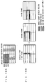
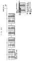
- FIG. 1 is a diagram showing an exemplary refresh operation in the case of applying the video coding method according to the first embodiment of the present invention to a CIF picture of H.261 or H.263 recommended by ITU (International Telecommunication Union).
- the CIF picture is of 352 by 288 dots, and this is divided into 22 by 18 blocks in units of a macroblock (hereinafter referred to as "MBLK") of 16 by 16 dots, and a GROUP OF BLOCKS (hereinafter referred to as "GOB”) is further formed every 11 by 3 blocks.
- MBLK macroblock
- GROUP OF BLOCKS hereinafter referred to as "GOB”
- the CIF picture is formed by 2 by 6 GOBs, and each GOB is further formed by 11 by 3 MBLKs.
- block indicates MBLK
- group of blocks is not limited to GOB.
- the following description is made with reference to the case of assuming GOB as a group of blocks. Numbers from GOB1 to GOB12 are attached to GOBs in the order shown in FIG. 1.
- a refresh cycle T is 12 frames.
- a time or a period is thus expressed by the number of frames and it is regarded that coding performed on each block included in the same frame is performed at the same point.
- groups of blocks having the same positions in the frame among groups of blocks in each frame are not distinguished but identified as the same groups of blocks and referred to with the same number.
- the motion information management part 2704 determines whether or not there is motion of an object in the GOB during 12 frames previous to timing when the GOB is individually refreshed on the basis of information obtained from the coding part 2708 every frame .
- a method of comparing the magnitude of a motion vector of each MBLK in the GOB with a set threshold and assuming that there is motion in the object in the GOB if there are MBLKs having motion vectors exceeding the threshold in excess of a prescribed number can be employed.
- presence/absence of motion in the object in the GOB may be determined by comparing the coding quantity of each of 12 frames with a set threshold and determining that there is motion if there is at least one frame whose coding quantity exceeds the threshold.
- the mode selection part 2705 selects one of a whole-group refresh mode and a dispersed refresh mode as the refresh mode.
- the mode selection part 2705 selects the whole-group refresh mode and the whole-group refresh part 2706 controls the selectors in the coding part 2708, thereby INTRA-coding all MBLKs belonging to the GOB simultaneously (i.e., in a coding process for the same frame), i.e., performing whole-group refresh on the GOB.
- the mode selection part 2705 selects the dispersed refresh mode and the dispersed refresh part 2707 controls selectors in the coding part 2708, thereby performing INTRA coding on each MBLK in the GOB at timing varying with the MBLK (i.e., in a coding process for frames varying with the MBLK), i.e., performing dispersed refresh on the GOB.
- Timing information for coding including such refresh is generated by the coding timing management part 2703 and supplied to the coding part 2708 and the refresh cycle management part 2702.
- Timing information indicating the refresh cycle is generated by the refresh cycle management part 2702 and supplied to the motion information management part 2704, the whole-group refresh part 2706 and the dispersed refresh part 2707.
- FIG. 1 shows an operation in such a case that there has been motion in the object in GOB1 to GOB4 and in GOB9 to GOB12 in the first 12 frames.
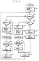
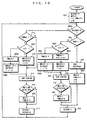
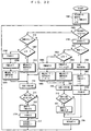
- FIG. 2 is a flow chart showing the video coding method used in the video coding apparatus 2701, and shows the aforementioned operation for one GOB.
- RCOUNT denotes a count value of the refresh cycle.
- MOV is a flag indicating presence/absence of motion in the object in the GOB, and "1" indicates that there is motion while "0" indicates that there is no motion.
- FMBLK is a flag indicating whether or not INTRA coding is performed at timing varying with the MBLK, i.e., a flag indicating whether or not dispersed refresh is performed, and "1" indicates that dispersed refresh is performed while "0” indicates that no dispersed refresh is performed.
- initialization of each variable and flag is first performed at a step 201.
- the refresh cycle management part 2702 initializes RCOUNT to "1”
- the mode selection part 2705 initializes MOV to "0", I to "1” and FMBLK to "0" respectively.
- the refresh cycle management part 2702 determines at a step 202 whether or not it is refresh timing. If the result is of refresh timing, the mode selection part 2705 determines at a step 203 whether or not there has been motion on the basis of the flag MOV. This flag MOV is set by the motion information management part 2704, as described later.
- the mode selection part 2705 selects the whole-group refresh mode.
- the whole-group refresh part 2706 performs at a step 204 whole-group refresh (also referred to as "GOB refresh") on the GOB, and the mode selection part 2705 resets MOV and FMBLK at a step 205.
- the refresh cycle management part 2702 initializes RCOUNT to "1" at a step 206, and the process returns to the step 202 in order to perform coding on the next frame, for again determining whether or not it is the refresh cycle.
- the mode selection part 2705 sets FMBLK at a step 207 for selecting the dispersed refresh mode and sets I to "1".
- the dispersed refresh part 2707 INTRA-codes MBLKs belonging to MBLKG(I) and increments I at a step 208.
- the coding part 2708 performs coding of blocks in the GOB other than MBLKG(I).
- the motion information management part 2704 determines at a step 210 whether or not there has been motion in the GOB in coding of the frame, and sets MOV at a step 211 when there has been motion.
- the refresh cycle management part 2702 initializes RCOUNT to "1" at a step 206 and the process returns to the step 202 in order to perform coding for a next frame, for again determining whether or not it is the refresh cycle.
- the motion information management part 2704 determines at a step 215 whether or not there has been motion in the GOB in coding of the frame, and sets MOV at a step 216 if there has been motion. Thereafter the refresh cycle management part 2702 increments RCOUNT at a step 217 and the process returns to the step 202 in order to perform coding on the next frame, for again determining whether or not it is the refresh cycle.
- the operations of the aforementioned steps 201 to 217 are performed on every GOB.
- a refresh block by INTRA coding of a group of blocks having no motion is divided into a number of transmission frames in a refresh cycle for refreshing one screen with no overhead.
- the number of INTRA-coded blocks per frame decreases and quantization in a smaller quantization step is enabled.
- cyclic motion of a group of blocks is dispersed in the refresh cycle, whereby a disturbance line can be eliminated in a still picture region.
- dispersed refresh is performed for a group of blocks having no motion, whereby, even if a transmission error occurs in a block finally refreshed as a group of blocks at a point when motion of a group of blocks having motion disappears, it is possible to refresh this.
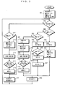
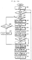
- FIG. 3 is a flow chart showing the video coding method of this case as to one GOB, and corresponds to the flow chart shown in FIG. 2.
- a flag REF and a variable ms showing the count value are newly introduced and initialized at a step 301 along with RCOUNT, MOV, I and MBLK.
- the whole-group refresh part 2706 performs GOB refresh at a step 304.
- the frequency for performing refresh at timing varying with the block may be reduced so that the dispersed refresh part 2707 completes refresh of the group of blocks in a cycle T' larger than T.
- coding efficiency can be improved while suppressing influence by a transmission error small by reducing the number of INTRA-coded blocks in a group of blocks where a still picture is continuous.
- a video coding method according to a second embodiment of the present invention and a video coding apparatus based on the video coding method are now described.
- the structure of this video coding apparatus is similar to that of the video coding apparatus 2701 according to the first embodiment, as shown in FIG. 13.
- parts identical to those of the video coding apparatus 2701 according to the first embodiment are denoted by the same reference numerals, to omit redundant description.
- timing of refresh by a whole-group refresh part 2706 is managed so that a refresh cycle management part 2702 introduces a frame including no group of blocks to be subjected to whole-group refresh into a refresh cycle.
- a refresh cycle management part 2702 introduces a frame including no group of blocks to be subjected to whole-group refresh into a refresh cycle.
- the coding efficiency is improved by INTER differential coding for improving the picture quality.
- the description is made with reference to the case of the CIF picture of H.261 or H.263 recommended in ITU.
- the refresh cycle T 33 frames and performing refresh in units of a GOB in continuous 12 frames therein, for example, frames not to be subjected to refresh in the unit of GOB are 21 frames, the coding efficiency is high during this period and the picture quality can be improved by the improvement of the efficiency when considering the coding quantity as constant. Further, the refresh can be performed in about one second.
- a dispersed refresh part 2707 disperses refresh of the GOB to be coded at timing varying with the MBLK described with reference to the first embodiment in the refresh cycle, thereby improving the coding efficiency.
- the first embodiment INTRA-codes 3 MBLKs per frame in order to refresh the MBLKs in the GOB in 11 frames
- MBLKs of the GOB may be refreshed in 33 frames in this embodiment when setting the refresh cycle to 33 frames as described above, for example, and hence one MBLK may be INTRA-coded per frame.
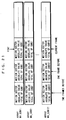
- a refresh operation is performed as shown in FIG. 4.
- FIG. 4 corresponds to FIG. 1 in the first embodiment, and parts slanted in FIG. 4 are blocks (MBLK) being subjected to INTRA coding.
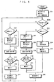
- FIG. 5 is a flow chart showing the video coding method according to this embodiment as to one GOB.
- the step 202 of the flow chart shown in FIG. 2 is replaced with a step 202b for determining whether or not a count value RCOUNT of the refresh cycle is equal to "33".
- the refresh cycle management part 2702 manages the timing of whole-group refresh by the whole-group refresh part 2706 and dispersed refresh by the dispersed refresh part 2707 and sets the refresh cycle to 33 frames.
- MBLKG(I) each becomes one MBLK, while the refresh may be rendered inconspicuous by performing mapping in order different from the number of MBLK.
- the number of INTRA-coded blocks to be INTRA-coded decreases below the number of blocks of the group of blocks in a frame including no group of blocks to be subjected to whole-group refresh, whereby both effects of video coding in high efficiency and refresh by INTRA coding can attained.
- a video coding method according to a third embodiment of the present invention and a video coding apparatus based on the video coding method are now described.
- the structure of this video coding apparatus is similar to that of the video coding apparatus 2701 according to the first embodiment, as shown in FIG. 13.
- parts identical to those of the video coding apparatus 2701 according to the first embodiment are denoted by the same reference numerals, to omit redundant description.
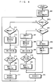
- FIG. 6 is a flow chart showing the video coding method according to this embodiment as to one GOB.
- the step 211 and the step 216 of the flow chart shown in FIG. 5 are changed to a step 601 and a step 602 respectively.
- the motion information management part 2704 resets FMBLK when motion is detected.
- the dispersed refresh by the dispersed refresh part 2707 is interrupted (see the step 212).
- FIG. 7 is a diagram showing an exemplary refresh operation in this embodiment.
- blocks of a group of blocks to be subjected to whole-group refresh after a lapse of a time T from start of the dispersed refresh are not subjected to dispersed refresh up to a point of the whole-group refresh after motion is detected, whereby the coding efficiency is further improved.
- a video coding method according to a fourth embodiment of the present invention and a video coding apparatus based on the video coding method are now described.
- the structure of this video coding apparatus is similar to that of the video coding apparatus 2701 according to the first embodiment, as shown in FIG. 13.
- parts identical to those of the video coding apparatus 2701 according to the first embodiment are denoted by the same reference numerals, to omit redundant description.
- a dispersed refresh part 2707 performs dispersed refresh from a point starting determination of presence/absence of motion of an object every group of blocks
- a motion information management part 2704 determines presence/absence of motion of the object every group of blocks every time coding one frame in parallel therewith up to a lapse of a time T, and with respect to a group of blocks in which motion exceeding a predetermined threshold is detected in the object
- a mode selection part 2705 makes the dispersed refresh part 2707 interrupt the dispersed refresh at the point
- FIG. 8 is a flow chart showing the video coding method according to this embodiment as to one GOB.
- the step 201 and the step 205 of the flow chart shown in FIG. 6 are changed to a step 801 and a step 802 respectively.
- a mode selection part 2705 sets FMBLK.
- FIG. 9 is a diagram showing an exemplary refresh operation in this embodiment.
- the process advances to a step 602 on the basis of a determination result in a step 215 in FIG.
- every block of the group of blocks is necessarily refreshed by dispersed refresh up to a lapse of the time T.
- detection of motion may be performed in advance in a next frame, for avoiding transmission of a block refreshed at different timing when there is motion in continuation.
- FIG. 10 is a flow chart showing an example of such a video coding method as to one GOB.
- a variable s is newly introduced and the steps 801, 802 and 207 of the flow chart shown in FIG. 8 are changed to a step 1001 including initialization of the variable s, a step 1002 including initialization of the variable s and a step 1004 including increment of the variable s while steps 1003, 1005, 1006, 1007, 1008 and 1009 are newly added.
- the mode selection part 2705 sets FMBLK at the step 1005 or 1008 and thereafter the dispersed refresh part 2707 performs refresh at the step 1006 or 1009 in MBLKG' (I') at different timing from MBLKG(I).
- a frame not to be subjected to refresh may be present in MBLKG'(I'), and a time for entirely refreshing a group of blocks is greater than T.
- FIG. 10 is modulo that I' returns to 1 when reaching a certain value.
- a method such as that described with reference to the first embodiment can be employed.
- a method of comparing the motion vector absolute value total of each MBLK in the GOB with a previously set threshold and determining that there is motion in the object in the GOB when the total exceeds the threshold may be employed.
- a video coding method according to a fifth embodiment of the present invention and a video coding apparatus based on the video coding method are now described.
- the structure of this video coding apparatus is similar to that of the video coding apparatus 2701 according to the first embodiment, as shown in FIG. 13.
- parts identical to those of the video coding apparatus 2701 according to the first embodiment are denoted by the same reference numerals, to omit redundant description.
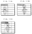
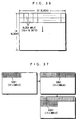
- dispersed refresh is performed on a group of blocks of the remaining half region while, when the moving object moves at the center of the screen as shown in FIG. 11B, motion is detected in all groups of blocks and hence whole-group refresh is performed on all groups of blocks.
- blocks to be subjected to INTRA coding over two frames or three frames or blocks inhibited from motion compensation over two frames or three frames increase even if halving the number of blocks of a group of blocks to be subjected to whole-group refresh as described with reference to the description of background art, and hence the coding efficiency is reduced and the generated coding quantity is not much reduced.
- frames including a group of blocks to be subjected to whole-group refresh increase when the number of the groups of blocks increases and hence frames including no group of blocks to be subjected to whole-group refresh decrease assuming that the refresh cycle is left intact. Consequently, the coding efficiency is reduced and the picture quality is deteriorated.
- a group of blocks is further L-divided while leaving intact the magnitude of the group of blocks and the timing for whole-group refresh for the group of blocks in the video coding method according to the third embodiment or the fourth embodiment, a motion information management part 2704 determines motion of an object for each region obtained by the dividing and a whole-group refresh part 2706 simultaneously refreshes a region determined as having motion exceeding a predetermined threshold in an object at timing for refreshing a group of blocks including the region.
- each GOB is divided into two left and right regions, as shown in FIG. 11C.
- presence/absence of motion is independently detected on the left and the right as to each GOB for also independently deciding whether the region is simultaneously refreshed or a block in the region is refreshed at different timing.
- the timing for performing refresh is rendered common.
- this embodiment assumes that, in this case, the timing for refreshing each of the left and right regions of each GOB is identical and detection of motion and selection of a refresh mode are independently performed as to each of the left and right regions of each GOB, and executes each step shown in any flow chart of FIG. 2, FIG. 3, FIG. 5, FIG. 6, FIG. 8 and FIG. 10, thereby performing video coding.
- motion of an object small as compared with a group of blocks can be efficiently refreshed, and it is possible to obtain a picture having smaller disturbance resulting from refresh.
- the method of dividing is not restricted to this but the GOB may be divided into three portions, i.e., left, middle and right portions, or may be divided into upper and lower portions. Further, the dividing may not be uniform.
- a video coding method according to a sixth embodiment of the present invention and a video coding apparatus based on the video coding method are now described.
- the structure of this video coding apparatus is similar to that of the video coding apparatus 2701 according to the first embodiment, as shown in FIG. 13.
- parts identical to those of the video coding apparatus 2701 according to the first embodiment are denoted by the same reference numerals, to omit redundant description.
- this embodiment changes the order of refreshing the groups of blocks in the video coding methods according to the first to fifth embodiments in response to the characteristics of an object of a picture to be coded and transmitted.
- this embodiment refreshes vertically and transversely arranged groups of blocks in the vertical direction when the object is vertically long or the object moves in the vertical direction while transversely refreshing the vertically and transversely arranged groups of blocks when the object is transversely long or the object moves in the transverse direction.
- refresh is performed in order of GOB1 ⁇ GOB2 ⁇ GOB3 ⁇ ... ⁇ GOB12, giving preference to the transverse direction as shown in FIG.
- the shape (whether vertically long or transversely long) of the object and the motion direction are supposed with information of a motion vector and the like obtained from a coding part 2708, for example, and a whole-group refresh part 2706 performs refresh in an order based on the result of the supposition.
- groups of blocks to be subjected to whole-group refresh are continuous, whereby refresh can be efficiently performed while the number of continuous frames including no groups of blocks to be subjected to whole-group refresh increases and hence the picture quality can be improved by highly efficient video coding utilizing Inter-frame correlation.
- a video coding method according to a seventh embodiment of the present invention and a video coding apparatus based on the video coding method are now described.
- the structure of this video coding apparatus is similar to that of the video coding apparatus 2701 according to the first embodiment, as shown in FIG. 13.
- parts identical to those of the video coding apparatus 2701 according to the first embodiment are denoted by the same reference numerals, to omit redundant description.
- the predetermined threshold is employed for determination as to whether or not whole-group refresh is performed on a divided region for performing whole-group refresh when motion of an object in the divided region exceeds the threshold on the assumption that the region has motion.
- a region not moving in practice is determined as a moving region and subjected to whole-group refresh or a region moving in practice is determined as not moving and subjected to no whole-group refresh.
- the threshold employed for the determination as to whether or not whole-group refresh is performed is set high in order to overcome the aforementioned inconvenience, in the case that and the motion of the object is small, a region where the object moves in practice is determined as a region having no motion of the object and subjected to no whole-group refresh despite the motion. Assuming that a transmission error occurs at this time, picture quality deterioration resulting from mismatch between frame memories on the coding side and the decoding side propagates to subsequent picture frames.
- the seventh embodiment of the present invention is characterized in that, in order to solve the aforementioned problem, threshold set processing of not fixing a threshold employed for determination as to whether or not whole-group refresh is performed but setting the threshold in response to vibration of a camera every time coding a frame.
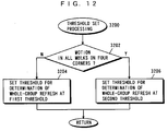
- FIG. 12 is a flow chart showing the procedure of the threshold set processing in this embodiment.
- two thresholds i.e., a first threshold employed when the camera has no vibration and a second threshold employed when the camera vibrates are previously prepared, and the second threshold is set to be greater than the first threshold.
- This threshold set processing is executed by a motion information management part 2704 every time coding a frame.
- a determination is first made as to whether or not the camera vibrates by detecting whether or not there is motion in all MBLKs on four corners in a picture frame in this threshold set processing (step 3202).
- step 3204 If there is at least one MBLK having no motion in the MBLKs on four corners in the picture frame, it is determined that the camera is not in vibration and the threshold employed for determining whether or not whole-group refresh is performed is set at the first threshold (step 3204). When there is motion in all MBLKs on the four corners in the picture frame, on the other hand, it is determined that the camera vibrates and the threshold employed for determination as to whether or not whole-group refresh is performed is set at the second threshold (step 3206).
- the aforementioned problem is solved by changing the threshold in response to vibration of the camera, and effective refresh responsive to the set state of the camera or the external environment is enabled.
- the threshold employed for determination as to whether or not whole-group refresh is performed is set in response to the blur quantity of the camera or the picture.
- presence/absence of camera vibration is determined by motion in the MBLKs on the four corners in the frame
- presence/absence of vibration of the camera may be determined from a group of MBLKs in contact with the upper end, the lower end, the right end and the left end of the frame.
- presence/absence of vibration of the camera may be determined employing a part such as a gyro other than that for picture processing.
- the aforementioned seventh embodiment is assumed to have two thresholds, i.e., the first threshold employed when the camera is not in vibration and the second threshold employed when the camera vibrates
- the threshold may be adaptively set in response to the motion quantity of the MBLKs on the four corners in the frame. For example, the average of the motion quantity of the MBLKs on the four corners may be set as the threshold as to whether or not whole-group refresh is performed.
- FIG. 26 is a block diagram showing the structure of a picture transmission system based on a video coding method according to an eighth embodiment of the present invention.
- This system comprises a video coding apparatus 2801 and a video decoding apparatus 2813.
- the video coding apparatus 2801 performs compression coding on an input picture Imi and transmits coded data obtained by this coding.
- the video decoding apparatus 2813 receives the coded data transmitted from the video coding apparatus 2801, performs decoding and outputs a picture obtained by this decoding as an output picture Imo.
- the video decoding apparatus 2813 further detects whether or not there is a transmission error in the coded data transmitted from the video coding apparatus 2801, and if detecting an error, reports the video coding apparatus 2801 about the error.
- the video coding apparatus 2801 has a coding part 2812 performing coding combining inter-picture coding and intra-picture coding, and additionally comprises, in order to perform refresh by making the coding part 2812 perform INTRA coding, an error notice holding part 2803, a first mode selection part 2802, a coding timing management part 2804, a motion information hold time management part 2805, a motion information storage management part 2806, a motion information hold time calculation part 2807, a second mode selection part 2808, a whole-group refresh part 2809 including a motion vector search range limit part 28091, a dispersed refresh part 2810, and a DCT refresh part 2811.
- the structure of the coding part 2812 is similar to the structure of the conventional encoder 116 shown in FIG. 33, and in the coding part 2812, selectors corresponding to the selectors 123 and 124 of the encoder 116 are controlled by the whole-group refresh part 2809, the dispersed refresh part 2810 and the DCT refresh part 2811.
- the video decoding apparatus 2813 comprises a decoding part 2816, an error detection part 2815 and an error notice part 2814.
- the error detection part 2815 receives the coded data transmitted from the video coding apparatus 2801 and detects whether or not there is a transmission error, while supplying the received coded data to the decoding part 2816.
- the decoding part 2816 decodes the coded data and outputs the picture obtained by the decoding as the output picture Imo.
- the error notice part 2814 transmits an error notice message indicating the transmission error detected by the error detection part 2815 to the video coding apparatus 2801. This error notice message is received and held by the error notice holding part 2803 in the video coding apparatus 2801 as described above.
- each part of the video coding apparatus 2801 may be directly implemented by hardware, while the same can be implemented employing software.
- each part of the video coding apparatus 2801 can be implemented by forming the video coding apparatus with a CPU (Central Processing Unit), a memory and an external memory device so that the CPU executes a prescribed program (hereinafter referred to as "video coding program" similarly to the first embodiment) loaded from the external memory device in the memory, for example.
- the video coding program is typically provided by a storage medium (floppy disk, CD-ROM, DVD or the like) storing the program.
- the user sets a purchased storage medium in the aforementioned video coding apparatus 2801, make the apparatus read the video coding program stored therein and installs the same in a memory device such as a hard disk unit.
- a video coding program transmitted to the video coding apparatus 2801 through a communication line online may be installed in the memory device.
- the maker may previously install the video coding program in the memory device before shipping the video coding apparatus. The program installed in such a manner is loaded in the memory from the memory device and executed by the CPU.
- FIG. 14 is a diagram showing an exemplary refresh operation in the case of applying the video coding method according to the eighth embodiment of the present invention to the CIF picture of H.261 or H.263 recommended by ITU (International Telecommunication Union).
- the CIF picture is of 352 by 288 dots, and this is divided into 22 by 18 blocks in units of a macroblock (MBLK) of 16 by 16 dots, and a GROUP OF BLOCKS (GOB) is formed every 11 by 3 blocks.
- MBLK macroblock
- GOB GROUP OF BLOCKS
- the CIF picture is formed by 2 by 6 GOBs, and each GOB is further formed by 11 by 3 MBLKs.
- "block” indicates MBLK, while a "group of blocks” is not limited to GOB.
- the motion information storage management part 2806 regularly determines and stores whether or not there is motion of an object in each GOB every frame in each frame previous to the point of coding by at least a time RTmax on the basis of the information obtained from the coding part 2812.
- the time RTmax is a time from coding up to a point when an error notice message therefor is returned from the decoding side.
- a determination method for presence/absence of motion a method of comparing the magnitude of a motion vector of each MBLK in the GOB with a predetermined threshold and determining that the object in the GOB has motion if MBLKs having motion vectors exceeding the threshold are present in excess of a prescribed number.
- presence/absence of motion in the object in the GOB may be determined by comparing the coding quantity with a predetermined threshold. Further, the motion vector absolute value total of each MBLK in the GOB may be compared with a predetermined threshold for determining that there is motion in the object as to a GOB having a value exceeding the threshold.
- the error detection part 2815 determines whether or not there is a transmission error in a picture frame to be decoded, and if any error is detected, the error notice part 2814 reports the coding side about this through a feedback transmission path, i.e., the error notice part 2814 returns the error notice message to the video coding apparatus 2801.
- a method of transmitting the coded data with an error detection code on the coding side so that the decoding side detects the error employing this can be employed.
- an error may be determined through the coding rule when inconsistency takes place in decoding.
- the error notice holding part 2803 receives this in the video coding apparatus 2801 and the first mode selection part 2802 starts the second mode selection part 2808 on the basis of this error notice.
- the second mode selection part 2808 started in this manner determines whether or not there has been motion in the object of each block up to a point preceding a point for starting coding after the error notice by the time RTmax on the basis of motion information stored by the motion information storage management part 2806. On the basis of the result of this motion determination, the second mode selection part 2808 decides GOBs having motion as whole-group refresh GOBs and GOBs having no motion as dispersed refresh GOBs.
- the whole-group refresh part 2809 entirely simultaneously refreshes the MBLKs in the GOBs successively GOB by GOB every time coding one frame from the point.
- the dispersed refresh part 2810 successively refreshes the MBLKs in the GOBs by MBLK by MBLK for one frame with respect to all dispersed refresh GOBs every time coding one frame from the point.
- slanted parts are blocks being subjected to INTRA coding.
- GOB5 to GOB12 are decided as dispersed refresh GOBs since there has been no motion in the object in the regions during the time RTmax.
- the refresh on GOB5 to GOB12 decided as dispersed refresh GOBs is ended.
- the first mode selection part 2802 starts the DCT refresh part 2811, and the DCT refresh part 2811 executes the refresh stipulated in ITU-T recommendation H.261 for the purpose of refreshing accumulation of calculation errors in discrete cosine transform (DCT) on the coding side and the decoding side at the rate of one MBLK per frame, for example.
- DCT discrete cosine transform
- FIG. 15 is a flow chart showing the video coding method used in the video coding apparatus 2801.
- FCNT indicates how many frames the motion vector absolute value total of each GOB of frames having been coded up to the current point are stored in arrays MV_GOB1 to MV_GOB12 described later, while RE is a refresh end flag, "1" indicates that refresh processing is ended and "0" indicates that refresh processing is in continuation.
- FCNT is initialized to "0" while the flag RE is set at a step 1600. Then, start of coding is determined at a step 1601.
- a picture signal from a camera or the like is inputted at the rate of 30 frames per second, the so-called "frame skip" of skipping frames in coding may be performed depending on the balance between the communication rate of the transmission path transmitting the coded data and the coded data quantity.
- a coding control part in the coding part 2812 determines which frame is coded and which frame is frame-skipped with reference to the remaining data quantity or the like of a buffer.
- an instruction of coding is outputted. If this instruction for coding is not outputted, the process waits at a step 1601, while the process advances to a step 1603 if the instruction for coding is outputted.
- the first mode selection part 2802 determines presence/absence of error notice from the decoding side.
- the error notice holding part 2803 stores data (hereinafter referred to as "error notice data") indicating presence/absence of error notice from a point previously performing coding up to the current point.
- error notice data data indicating presence/absence of error notice from a point previously performing coding up to the current point.
- the first mode selection part 2802 determines presence/absence of error notice on the basis of this error notice data, and the process advances to a step 1604 if there is no error notice.
- the DCT refresh part 2811 performs processing of DCT refresh on the current frame. By this processing of DCT refresh, coded data for one frame of the input picture Imi is obtained.
- the motion information storage management part 2806 stores motion information on the basis of the result of coding of the current frame by this DCT refresh (hereinafter referred to as "motion information storage management processing").
- FIG. 20 is a flow chart showing the procedure of the motion information storage management processing.
- arrays MV_GOB1 to MV_GOB12 are arrays storing the motion vector absolute value total of each GOB of frames coded from a point previous by the time RTmax up to the current point.
- the variable FCNT indicating the number of frames in which the motion vector absolute value total is stored in the arrays MV_GOB1 to MV_GOB12 at the current pint of time, is initialized at the step 1600 in FIG. 15 as described above and used as a pointer for storing motion information in the arrays MV_GOB1 to MV_GOB12.
- a step group 2101 of FIG. 20 the numbers of GOBs to be subjected to whole-group refresh in a frame are detected every time coding the frame, for adding a value exceeding the threshold for deciding whether whole-group refresh is performed or dispersed refresh is performed to the total of the motion vector absolute values of each GOB to be subjected to whole-group refresh.
- the absolute value total of the motion vectors of each GOB is stored in a part indicated by the variable FCNT in the region of each array of the arrays MV_GOB1 to MV_GOB12.
- FIG. 21 shows exemplary storage management of motion information in the arrays MV_GOB1 to MV_GOB12.
- motion information of each GOB is stored in the arrays MV_GOB1 to MV_GOB12 following motion information of frames coded previously.
- the motion information of the frames stored in the arrays MV_GOB1 to MV_GOB12 is employed for determination as to whether whole-group refresh is performed or dispersed refresh is performed.
- steps 1614 to 1616 are successively executed, while these steps are described later.
- the second mode selection part 2808 classifies each GOB into a whole-group refresh GOB which is a GOB to be subjected to whole-group refresh and a dispersed refresh GOB which is a GOB to be subjected to dispersed refresh from the motion information of each frame stored in the arrays MV_GOB1 to MV_GOB12. In other words, it selects the mode for refresh of each GOB on the basis of the motion information as to each GOB (hereinafter referred to as "motion determination mode selection processing").
- Fig. 16 is a flow chart showing the procedure of the motion determination mode selection processing.
- a variable cnt1 is an internal counter, and employed as a pointer for the arrays MV_GOB1 to MV_GOB12.
- the absolute value total of the motion vectors of each GOB of the frames coded previously is stored as shown in FIG. 21 by the motion information storage management processing shown in FIG. 20.
- information hereinafter referred to as "refresh information" indicating whether whole-group refresh is performed or dispersed refresh is performed on each GOB is stored as shown in FIG.
- the variable FCNT is the number of frames in which the absolute value total of the motion vectors of each GOB is stored in the arrays MV_GOB1 to MV_GOB12 at the current point as already described.
- variable cnt1 is first initialized to "0" at a step 1701. Then, the variable cnt1 is compared with the variable FCNT at a step 1702, for ending the motion determination mode selection processing when the variable cnt1 is greater than the variable FCNT while advancing to a step 1703 when the variable cnt1 is less than the variable FCNT.
- the process advances to a step 1704 if greater than the threshold, while advancing to a step 1705 if less than the threshold.
- the logical sum of an array element REF[0] and "1" is obtained and this logical sum is re-stored as the array element REF[0].
- the logical sum of an array element REF[0] and "0” is obtained and this logical sum is re-stored as the array element REF[0].
- the process advances to a step 1706.
- the process advances to a step 1707 if greater than the threshold, while advancing to a step 1708 if less than the threshold.
- the logical sum of an array element REF[1] and "1” is obtained and this logical sum is re-stored as the array element REF[1].
- the logical sum of an array element REF[1] and "0" is obtained and this logical sum is re-stored as the array element REF[1].
- each GOB is classified into a GOB to be subjected to whole-group refresh and a GOB to be subjected to dispersed refresh, and refresh information indicating the result of the classification is stored in the array REF as shown in FIG. 17.
- the refresh information stored in the array REF is cleared to zero when refresh of the GOB is completed.
- the array REF is formed by 12 regions, so that refresh information for GOB1 is stored in the region of the array element REF[0], refresh information for GOB2 is stored in the region of the array element REF[1], and similarly, refresh information for GOB3 to GOB12 is stored in array elements REF[2] to REF[11] respectively.
- the second mode selection part 2808 After performing the aforementioned motion determination mode selection processing, the second mode selection part 2808 resets the refresh end flag RE at a step 1608.
- coding with motion vector limit is performed.
- the motion vector search range limit part 28091 is provided in the whole-group refresh part 2809 and this motion vector search range limit part 28091 controls motion compensation INTER coding in the coding part 2812, whereby coding with motion vector limit at the step 1609 is performed.
- the coding processing with motion vector limit is now described with reference to FIG. 18 and FIGS. 19A and 19B.
- FIG. 18 is a flow chart showing the coding processing with motion vector limit.
- FIGS. 19A and 19B are diagrams showing limit examples of the motion vector search range.
- the coding part 2812 limits the motion vector search range not to make reference from an unrefreshed region in a region to be subjected to whole-group refresh when performing motion compensation INTRA coding on each MBLK and performs coding. Concrete examples of this operation are described with reference to FIGS. 19A and 19B.
- FIG. 19A shows regions to be subjected to whole-group refresh. In this example, GOB1, 3 and 5 are the regions to be subjected to whole-group refresh.
- FIG. 19A shows regions to be subjected to whole-group refresh. In this example, GOB1, 3 and 5 are the regions to be subjected to whole-group refresh.
- FIG. 19B shows MBLKs to be subjected to motion vector search limit during whole-group refresh.
- an error may spread when referring to GOB1, 3 and 5 since GOB1, 3 and 5 are not refreshed in the first frame after starting of refresh, and hence the motion vector search range for the MBLKs adjacent to GOB1, 3 and 5 is so limited as not to make reference from GOB1, 3 and 5.
- the motion vector search range for the MBLKs adjacent to GOB1, 3 and 5 is so limited as not to make reference from GOB1, 3 and 5.
- the second frame there is no apprehension that an error spreads even if referring to GOB1 since GOB1 is completely subjected to whole-group refresh, and hence motion vector search limit on MBLKs adjacent to unrefreshed regions, i.e., MBLKs adjacent to GOB3 and 5 is performed.
- the motion vectors may be so limited that blocks of each GOB do not refer to blocks of GOBs other than the GOB during a period for performing refresh simultaneously by INTRA coding.
- the second mode selection part 2808 refers to the array REF, and performs dispersed refresh on a GOB decided as a dispersed refresh GOB at the step 1607 by the dispersed refresh part 2810.
- the second mode selection part 2808 refers to the array REF and performs whole-group refresh on a GOB decided as a whole-group refresh GOB at the step 1607 by the whole-group refresh part 2809.
- motion information indicating that there is motion in the GOB is stored at the step 1606.
- the second mode selection part 2808 determines whether or not the processing of refresh after error notice is ended. If it is consequently determined that the processing of refresh after error notice is ended, the refresh end flag RE is set at a step 1613 and thereafter the process advances to the step 1606. If it is consequently determined that the processing of refresh after error notice is not ended, the process directly advances to the step 1606.
- the motion information for each GOB of the current frame is stored in the arrays MV_GOB1 to MV_GOB12 as shown in FIG. 21 by the motion information storage management processing shown in FIG. 20, as described above.
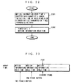
- FIG. 22 is a flow chart showing the procedure of the motion information hold time calculation processing.
- FIG. 23 shows exemplary storage of the motion information hold time in an array TIME.
- the motion information hold time is a time necessary for determining that receiving is made on the decoding side with no error, and an error reported from the decoding side after a lapse of the motion information hold time from coding of a certain frame can be determined as not an error for this frame.
- the array TIME is an array holding the motion information hold time.
- the variable FCNT is the number of frames in which the motion vector absolute value total as motion information is stored in the arrays MV_GOB1 to MV_GOB12 at the current point as already described, and used as a pointer for the array TIME.
- the motion information hold time calculation part 2807 first calculates the motion information hold time from the buffer data quantity at the current point, the error detection time of the decoding side, the transmission time of the error notice message and the transmission rate at a step 2301. Then, at a step 2302, the motion information hold time calculation part 2807 stores the calculated motion information hold time in a region of the array TIME indicated by the variable FCNT. The motion information hold time for each frame is stored in the array TIME following motion information hold time for frames coded previously, as shown in FIG. 23.
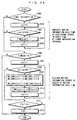
- FIG. 24 is a flow chart showing the procedure of the motion information hold time management processing.
- the variable cnt1 is a counter.
- the variable FCNT is the number of frames in which the motion information is stored in the arrays MV_GOB1 to MV_GOB12 at the current point as already described, and used as a pointer for the array TIME and the arrays MV_GOB1 to MV_GOB12.
- the array TIME is an array storing the motion information hold time, as already described.
- the total of the absolute values of the motion vectors of each GOB of the frames coded previously is stored as the motion information.
- the process advances to a step 2506 for determining whether or not the value of an array TIME[0] is "0". Consequently, the motion information hold time management processing is ended if the value of the array TIME[0] is not "0", while the process advances to a step 2507 if the value of the array TIME[0] is "0".
- variable cnt1 is set to 1 and the variable FCNT is compared with the variable cnt1 at a next step 2508.
- values of the arrays MV_GOB1 to MV_GOB12 indicated by the variable cnt1 are stored in regions of the arrays MV_GOB1 to MV_GOB12 indicated by a variable cnt1-1 respectively at a step 2509.
- the value of the array TIME indicated by the variable cnt1 is stored in a region of the array TIME indicated by the variable cnt1-1.
- variable cnt1 is incremented at a step 2511, and the process returns to the step 2508. Thereafter the steps 2508 to 2511 are repeatedly executed while the variable cnt1 is not more than the variable FCNT, whereby motion information of frames passing the motion information hold time is discarded from the arrays MV_GOB1 to MV_GOB12, and exchange of the values stored in the arrays MV_GOB1 to MV_GOB12 is performed. Also in relation to the values stored in the array TIME, exchange is similarly performed.
- the process advances to a step 2512 for determining whether or not the variable FCNT is greater than "0". If the variable FCNT is greater than "0" as a result, the variable FCNT is decremented at a step 2513 and thereafter the motion information hold time management processing is ended. If the variable FCNT is not more than "0", the motion information hold time management processing is directly ended.
- motion information hold time management processing it follows that, by discarding motion information of the frames passing the motion information hold time set when coding the frames, only motion information of the minimum necessary frame employed for determination as to whether whole-group refresh is performed or dispersed refresh is performed is held.
- the maximum time from coding up to return of error notice therefor may be assumed and this may be regarded as RTmax (fixed value), thereby omitting the step 1614 of the motion information hold time calculation processing.
- variable FCNT is incremented at a step 1616 and the process returns to the step 1601 in order to perform coding on a next frame. Thereafter every time the steps 1601 to 1616 are executed, coding on the input picture Imi is performed frame by frame with the refresh operation similarly to the above.
- largeness/smallness of motion of the object per group of blocks can be determined going back to the point coding the frame of an error at the point when the error is reported from the decoding side to the coding side, whereby it is possible to simultaneously refresh only a necessary group of blocks when necessary, and it is possible to improve the coding efficiency without damaging error resistance.
- FIG. 25 shows that motion information for four frames is stored in the arrays MV_GOB1 to MV_GOB12 at a point receiving error notice, and in this case, a frame conceivably causing a transmission error is the oldest frame among these four frames. Only motion in GOB1 exceeds the threshold in this oldest frame, while there is motion exceeding the threshold in GOB2, 3 and 12 among the remaining frames. In this case, therefore, no whole-group refresh is performed on GOB12 not in contact with GOB1 among GOB1, 2, 3 and 12 determined as having motion exceeding the threshold according to the aforementioned method.
- the maximum time from coding up to return of error notice therefor may be assumed and this may be regarded as RTmax while giving a time varying with dispersion of the buffer size or of error notice as T for regarding a frame coded during a lapse of the time T from a point precedent by the time RTmax as a frame causing a transmission error.
- a video coding method according to a ninth embodiment of the present invention and a video coding apparatus based on the video coding method are now described.
- the structure of this video coding apparatus is similar to that of the video coding apparatus 2701 according to the first embodiment, as shown in FIG. 13.
- parts identical to those of the video coding apparatus 2701 according to the first embodiment are denoted by the same reference numerals, to omit redundant description.
- a refresh cycle management part 2702 calculates timing information indicating the refresh cycle for each GOB, and supplies the timing information to a motion information management part 2704, a whole-group refresh part 2706 and a dispersed refresh part 2707.
- a refresh cycle calculation method employed in the refresh cycle management part 2702 is now described with reference to FIGs. 32 and 33.
- FIG. 32 is a flow chart showing the video coding method according to this embodiment as to one GOB.
- the step 202b of the flow chart shown in FIG. 10 is changed to a step 202c, steps 3701 to 3704 are added, and a variable interval, a cycle set flag FPERI and a GOB flag FGOB are newly introduced.
- a determination is made as to whether or not the value of RCOUNT which is a count value is equal to the value of the variable interval. It is assumed that the refresh cycle is set in the variable interval.
- the cycle set flag FPERI is set to "1".
- the GOB flag FGOB is set to "1".
- the GOB flag FGOB is cleared to zero.
- the GOB flag FGOB is referred to in a flow chart of FIG. 33 described below.
- FIG. 33 is a flow chart showing the method of calculating the refresh cycle in this embodiment.
- a default value of the refreshed cycle is set in a variable T at a step 3601.
- a default value of a second refresh cycle is set at a variable T'.
- the second refresh cycle stands for a refresh cycle of dispersed refresh for a GOB in which a still state continues, i.e., a refresh cycle of the dispersed refresh in such a case that blocks of GOB being in the process of the dispersed refresh are INTRA-coded in frames varying with the block continuously at least S times.
- step 3604 When it is determined at the step 3604 that the cycle set flags FPERI for all GOBs are set to "1", the process advances to a step 3605 for determining whether or not the values of RCOUNT for all GOBs are less than the value of the variable interval. Consequently, when the values of RCOUNT for all GOBs are less than the value of the variable interval, steps 3606 and 3607 are carried out thereby calculating a refresh cycle T''. If there is such a GOB for which the value of RCOUNT is greater than the value of the variable interval, the cycle set flags RPERI for all GOBs are cleared to zero at a step 3609 and the process advances to a step 3610.
- the above equation decides T'' so that the number of INTRA blocks in the refresh cycle is equal. Namely, according to the above equation, such a refresh cycle T'' that decrement of the number of INTRA-coded blocks in a group of blocks in which a still region continues and increment of the number of INTRA-coded blocks in a group of blocks of a region having motion are equal to each other is calculated. T'' thus calculated is set at the variable interval at a next step 3608. Thereafter the process advances to a step 3610.
- step 3610 coding processing such as that shown in FIG. 10 is performed on each GOB, and thereafter the process returns to the step 3603.
- the processing from the step 3606 up to the step 3608 is repeatedly executed from a point when each GOB refreshed in displacement frame by frame entirely enters a new refresh cycle until the first GOB of each GOB refreshed in displacement frame by frame enters a next refresh cycle.
- the refresh cycle (T'') is sequentially updated in response to the motion of the object.
- a group of blocks (a region serving as the reference for dividing in the fifth embodiment) is a GOB.
- deterioration of the picture quality caused by a transmission error can be kept in the GOB and error resistance can be improved even if the transmission error is generated in information in coding of a frame and the information is erroneous.
- control of the operation of simultaneously whole-group refresh performing refresh of the group of blocks and the operation of dispersed refresh performing refresh of the group of blocks at timing varying with the block can be simply performed.
- the refresh cycle has been set as 12 frames or 33 frames in each of the aforementioned embodiments, the refresh cycle is not restricted to these values. Resistance against errors is attained when shorting the refresh cycle, while the picture quality can be improved when contrarily retarding the refresh cycle.
- a frame to be currently coded includes a group of blocks to be subjected to whole-group refresh while a frame coded n (n ⁇ 1) frames before includes no group of blocks to be subjected to whole-group refresh
- the picture quality of the frame to be currently coded may be rendered inferior to the picture quality of the frame coded n frames before.
- the picture quality of the frame to be currently coded may be rendered superior to the picture quality of the frame coded n frames before.
- the information quantity between the frames can be smoothed and a motion picture having small frame skip can be obtained.
- quantization precision in coding may be changed.
- the picture quality can be improved when increasing the quantization precision, while the picture quality can be degraded when contrarily reducing the quantization precision.
- the quantization precision for change of the picture quality, the information quantity between the frames can be simply smoothed and a motion picture having small frame skip can be obtained by merely changing the parameter of the quantization precision.
- FIG. 27 is a block diagram showing the structure of a video coding apparatus 2701b for controlling quantization precision in the aforementioned manner.
- This video coding apparatus 2701b comprises, in addition to the structure elements shown in Fig. 13, a quantization precision control part 2712b for controlling quantization precision in a coding part 2708 on the basis of information obtained by a motion information management part 2704.
- the quantization precision control part 2712b first performs quantization precision set processing on each frame of an inputted picture Imi, and thereafter performs coding by any of the video coding methods of the aforementioned embodiments.
- FIG. 28 is a flow chart showing the procedure of this quantization precision set processing.
- the quantization precision control part 2712b controls quantization precision in the coding part 2708.
- the parameter of the quantization precision is changed by a prescribed value thereby reducing the quantization precision for the frame to be currently coded (step 3006), and when the frame to be currently coded includes no group of blocks to be subjected to whole-group refresh while the frame coded n frames before includes a group of blocks to be subjected to whole-group refresh, the parameter of the quantization precision is changed by a prescribed time thereby improving the quantization precision for the frame to be currently coded (step 3010), and thereafter the quantization precision set processing is ended. If corresponding to neither case, the quantization precision set processing is ended without changing the quantization precision.
- the picture quality of MBLKs to be subjected to refresh may be rendered superior to the picture quality of the remaining MBLKs in the frame in a group of blocks to be subjected to refresh by INTRA coding at timing varying with the MBLK.
- the lower limit of the picture quality of the MBLKs to be subjected to refresh may be set so that the picture quality of each MBLK is not below the set lower limit.
- the picture quality of MBLKs to be subjected to refresh exceeds the set lower limit, further, the picture quality may be rendered substantially equal to the picture quality of the remaining MBLKs in the frame, while, when the picture quality of the MBLKs to be subjected to refresh is below the set lower limit, the picture quality of the MBLKs to be subjected to refresh may be set at the set lower limit.
- the quantization precision in coding may be changed as already described.
- the picture quality can be improved when increasing the quantization precision, while the picture quality can be degraded when contrarily reducing the quantization precision.
- quantization precision for change of the picture quality, quantization distortion resulting from refresh can be easily eliminated in the still region by merely changing the parameter of the quantization precision.
- FIG. 29 is a block diagram showing the structure of a video coding apparatus 2701c controlling quantization precision in the aforementioned manner.
- This video coding apparatus 2701c comprises, in addition to the structure elements shown in Fig. 13, a quantization precision control part 2712c controlling quantization precision in a coding part 2708 on the basis of timing information outputted from a dispersed refresh part 2707.
- FIG. 30 is a flow chart showing an exemplary procedure of dispersed refresh in the aforementioned video coding apparatus 2701c, and shows internal processing at the steps 208 and 213 in the flow chart of FIG. 2, for example.
- the quantization precision control part 2712c receives timing information indicating the period of dispersed refresh from a dispersed refresh part 2707 for improving quantization precision at the current point by first changing the parameter of the quantization precision by a prescribed value before coding blocks belonging to MBLKG(I) to be refreshed in a dispersed refresh mode (step 3102). Thereafter the MBLKs belonging to MBLKG (I) are INTRA-coded, i.e., refreshed (step 3104). After this refresh, the parameter of the quantization precision is returned to that before the change (step 3106), I is incremented (step 3108) and single dispersed refresh is ended.
- FIG. 31 is a flow chart showing another exemplary procedure of dispersed refresh in the aforementioned video coding apparatus 2701c.
- the quantization precision control part 2712c receives timing information indicating the period of dispersed refresh from the dispersed refresh part 2707, and first determines whether or not quantization precision at the current point is lower than a previously set lower limit before coding the blocks belonging to MBLKG (I) to be refreshed in the dispersed refresh mode (step 3114). Then, the quantization precision control part 2712c controls the quantization precision in the coding part 2708 in response to the result of this determination.
- step 3114 sets the quantization precision at the lower limit if the quantization precision is lower than the lower limit (step 3114), while setting the quantization precision at a degree substantially identical to quantization precision for the remaining MBLKs (blocks other than those for the current dispersed refresh) (step 3116). Thereafter the MBLKs belonging to MBLKG (I) are INTRA-coded, i.e., refreshed (step 3118). After this refresh, the quantization precision is returned to that before the change (step 3120), I is incremented (step 3122), and single dispersed refresh is ended.
Landscapes
- Engineering & Computer Science (AREA)
- Multimedia (AREA)
- Signal Processing (AREA)
- Compression Or Coding Systems Of Tv Signals (AREA)
Applications Claiming Priority (2)
| Application Number | Priority Date | Filing Date | Title |
|---|---|---|---|
| JP2694498 | 1998-02-09 | ||
| JP2694498 | 1998-02-09 |
Publications (2)
| Publication Number | Publication Date |
|---|---|
| EP0935396A2 true EP0935396A2 (fr) | 1999-08-11 |
| EP0935396A3 EP0935396A3 (fr) | 2004-08-11 |
Family
ID=12207274
Family Applications (1)
| Application Number | Title | Priority Date | Filing Date |
|---|---|---|---|
| EP99101689A Withdrawn EP0935396A3 (fr) | 1998-02-09 | 1999-02-08 | Appareil et méthode de codage vidéo |
Country Status (2)
| Country | Link |
|---|---|
| US (1) | US6333948B1 (fr) |
| EP (1) | EP0935396A3 (fr) |
Cited By (7)
| Publication number | Priority date | Publication date | Assignee | Title |
|---|---|---|---|---|
| WO2000018136A1 (fr) * | 1998-09-18 | 2000-03-30 | Sarnoff Corporation | Strategie de rafraichissement par zones dans une compression video |
| GB2353165A (en) * | 1999-06-04 | 2001-02-14 | Matsushita Electric Industrial Co Ltd | Image signal decoder and image signal display system compensating for inter-frame motion |
| WO2003043304A3 (fr) * | 2001-11-13 | 2004-04-08 | France Telecom | Procede de fourniture d'images fixes ou animees avec controle d'acces |
| CN102595124A (zh) * | 2011-01-14 | 2012-07-18 | 华为技术有限公司 | 图像编码解码方法、处理图像数据方法及其设备 |
| CN104125457A (zh) * | 2011-01-14 | 2014-10-29 | 华为技术有限公司 | 图像编码解码方法、处理图像数据方法及其设备 |
| CN107277519A (zh) * | 2017-06-30 | 2017-10-20 | 武汉斗鱼网络科技有限公司 | 一种判断视频帧的帧类型的方法及电子设备 |
| KR20190003548A (ko) * | 2016-04-29 | 2019-01-09 | 에이티아이 테크놀로지스 유엘씨 | 고효율 저딜레이 비디오 코딩을 위한 모션-적응적 인트라-리프레시 |
Families Citing this family (21)
| Publication number | Priority date | Publication date | Assignee | Title |
|---|---|---|---|---|
| US6499060B1 (en) | 1999-03-12 | 2002-12-24 | Microsoft Corporation | Media coding for loss recovery with remotely predicted data units |
| US6668016B1 (en) * | 1999-05-11 | 2003-12-23 | Matsushita Electric Industrial Co., Ltd. | Moving image coding method and apparatus, and moving image coding and decoding system |
| JP2002158992A (ja) * | 2000-11-22 | 2002-05-31 | Fujitsu Ltd | 画像配信装置、画像処理装置およびカメラ |
| EP1374430A4 (fr) * | 2001-03-05 | 2005-08-17 | Intervideo Inc | Systemes et procedes pour un codage robuste aux erreurs |
| JP4592998B2 (ja) * | 2001-04-25 | 2010-12-08 | パナソニック株式会社 | 画像情報の伝送方法及び伝送装置 |
| EP1454486A4 (fr) * | 2001-12-04 | 2009-03-25 | Polycom Inc | Procede et dispositif permettant de melanger des donnees video compressees |
| KR100508975B1 (ko) * | 2003-05-20 | 2005-08-17 | 주식회사 팬택 | 다층 레벨 연속 제거 알고리즘을 이용한 동영상 움직임추정 방법 |
| KR100584422B1 (ko) * | 2003-06-04 | 2006-05-26 | 삼성전자주식회사 | 영상데이터의 압축 장치 및 방법 |
| US20050201470A1 (en) * | 2004-03-12 | 2005-09-15 | John Sievers | Intra block walk around refresh for H.264 |
| KR100647948B1 (ko) * | 2004-03-22 | 2006-11-17 | 엘지전자 주식회사 | 적응적 인트라 매크로 블록 리프레쉬 방법 |
| US8634413B2 (en) | 2004-12-30 | 2014-01-21 | Microsoft Corporation | Use of frame caching to improve packet loss recovery |
| US9661376B2 (en) * | 2005-07-13 | 2017-05-23 | Polycom, Inc. | Video error concealment method |
| US8774272B1 (en) | 2005-07-15 | 2014-07-08 | Geo Semiconductor Inc. | Video quality by controlling inter frame encoding according to frame position in GOP |
| WO2007122554A2 (fr) * | 2006-04-21 | 2007-11-01 | Koninklijke Philips Electronics N.V. | Profils reguliers de precision par amelioration d'image |
| US8115726B2 (en) * | 2007-10-26 | 2012-02-14 | Hewlett-Packard Development Company, L.P. | Liquid crystal display image presentation |
| US9172960B1 (en) * | 2010-09-23 | 2015-10-27 | Qualcomm Technologies, Inc. | Quantization based on statistics and threshold of luminanceand chrominance |
| JP5812808B2 (ja) * | 2011-01-05 | 2015-11-17 | キヤノン株式会社 | 画像処理装置及び画像処理方法 |
| SG11201502126RA (en) * | 2012-09-28 | 2015-05-28 | Sony Corp | Image processing device and method |
| US20140294072A1 (en) * | 2013-03-27 | 2014-10-02 | Magnum Semiconductor, Inc. | Apparatuses and methods for staggered-field intra-refresh |
| CN110267008B (zh) * | 2019-06-28 | 2021-10-22 | Oppo广东移动通信有限公司 | 图像处理方法、装置、服务器及存储介质 |
| CN115088279B (zh) * | 2020-01-07 | 2024-12-17 | 高通股份有限公司 | 交叉路口轨迹确定和消息接发 |
Family Cites Families (13)
| Publication number | Priority date | Publication date | Assignee | Title |
|---|---|---|---|---|
| JPH04117882A (ja) * | 1990-09-07 | 1992-04-17 | Matsushita Electric Ind Co Ltd | 動画像符号化装置 |
| JP3166789B2 (ja) * | 1992-02-24 | 2001-05-14 | ソニー株式会社 | ビデオ信号の伝送方法 |
| JP3184011B2 (ja) * | 1992-07-20 | 2001-07-09 | 株式会社東芝 | 帯域圧縮信号処理装置 |
| JPH0837663A (ja) * | 1994-07-22 | 1996-02-06 | Canon Inc | 符号化装置 |
| US5805223A (en) * | 1994-05-25 | 1998-09-08 | Canon Kk | Image encoding apparatus having an intrapicture encoding mode and interpicture encoding mode |
| JP3618783B2 (ja) * | 1994-05-25 | 2005-02-09 | キヤノン株式会社 | 画像符号化方法及び画像符号化装置 |
| JP3258840B2 (ja) * | 1994-12-27 | 2002-02-18 | シャープ株式会社 | 動画像符号化装置および領域抽出装置 |
| JP3630474B2 (ja) * | 1995-07-14 | 2005-03-16 | 沖電気工業株式会社 | 動画像伝送システム及び動画像伝送装置 |
| JP3157101B2 (ja) * | 1996-03-08 | 2001-04-16 | 沖電気工業株式会社 | 画像符号化方法及び画像符号化装置 |
| JP3823275B2 (ja) * | 1996-06-10 | 2006-09-20 | 富士通株式会社 | 動画像符号化装置 |
| US6037987A (en) * | 1997-12-31 | 2000-03-14 | Sarnoff Corporation | Apparatus and method for selecting a rate and distortion based coding mode for a coding system |
| US6160848A (en) * | 1998-01-22 | 2000-12-12 | International Business Machines Corp. | Conditional replenishment device for a video encoder |
| JP3905969B2 (ja) * | 1998-01-30 | 2007-04-18 | 株式会社東芝 | 動画像符号化装置および動画像符号化方法 |
-
1999
- 1999-02-08 EP EP99101689A patent/EP0935396A3/fr not_active Withdrawn
- 1999-02-09 US US09/247,081 patent/US6333948B1/en not_active Expired - Fee Related
Cited By (20)
| Publication number | Priority date | Publication date | Assignee | Title |
|---|---|---|---|---|
| WO2000018136A1 (fr) * | 1998-09-18 | 2000-03-30 | Sarnoff Corporation | Strategie de rafraichissement par zones dans une compression video |
| US6304295B1 (en) | 1998-09-18 | 2001-10-16 | Sarnoff Corporation | Region-based refresh strategy for video compression |
| GB2353165A (en) * | 1999-06-04 | 2001-02-14 | Matsushita Electric Industrial Co Ltd | Image signal decoder and image signal display system compensating for inter-frame motion |
| GB2353165B (en) * | 1999-06-04 | 2003-08-27 | Matsushita Electric Industrial Co Ltd | Image signal decoder and image signal display system |
| US6697431B1 (en) | 1999-06-04 | 2004-02-24 | Matsushita Electric Industrial Co., Ltd. | Image signal decoder and image signal display system |
| US7092444B2 (en) | 1999-06-04 | 2006-08-15 | Matsushita Electric Industrial Co., Ltd. | Image signal decoder for determining interframe motion |
| US7106800B2 (en) | 1999-06-04 | 2006-09-12 | Matsushita Electric Industrial Co., Ltd. | Image signal decoder selectively using frame/field processing |
| WO2003043304A3 (fr) * | 2001-11-13 | 2004-04-08 | France Telecom | Procede de fourniture d'images fixes ou animees avec controle d'acces |
| CN102595124B (zh) * | 2011-01-14 | 2014-07-16 | 华为技术有限公司 | 图像编码解码方法、处理图像数据方法及其设备 |
| WO2012095036A1 (fr) * | 2011-01-14 | 2012-07-19 | 华为技术有限公司 | Procédés de codage et de décodage d'image, procédé de traitement de données d'image et appareil correspondant |
| CN102595124A (zh) * | 2011-01-14 | 2012-07-18 | 华为技术有限公司 | 图像编码解码方法、处理图像数据方法及其设备 |
| CN104125457A (zh) * | 2011-01-14 | 2014-10-29 | 华为技术有限公司 | 图像编码解码方法、处理图像数据方法及其设备 |
| US9485504B2 (en) | 2011-01-14 | 2016-11-01 | Huawei Technologies Co., Ltd. | Image coding and decoding method, image data processing method, and devices thereof |
| US9979965B2 (en) | 2011-01-14 | 2018-05-22 | Huawei Technologies Co., Ltd. | Image coding and decoding method, image data processing method, and devices thereof |
| US10264254B2 (en) | 2011-01-14 | 2019-04-16 | Huawei Technologies Co., Ltd. | Image coding and decoding method, image data processing method, and devices thereof |
| KR20190003548A (ko) * | 2016-04-29 | 2019-01-09 | 에이티아이 테크놀로지스 유엘씨 | 고효율 저딜레이 비디오 코딩을 위한 모션-적응적 인트라-리프레시 |
| EP3449632A4 (fr) * | 2016-04-29 | 2019-12-11 | ATI Technologies ULC | Intra-rafraîchissement adaptatif en fonction du mouvement pour codage vidéo à haut rendement et à faible retard |
| US10652572B2 (en) | 2016-04-29 | 2020-05-12 | Ati Technologies Ulc | Motion-adaptive intra-refresh for high-efficiency, low-delay video coding |
| CN107277519A (zh) * | 2017-06-30 | 2017-10-20 | 武汉斗鱼网络科技有限公司 | 一种判断视频帧的帧类型的方法及电子设备 |
| CN107277519B (zh) * | 2017-06-30 | 2019-11-15 | 武汉斗鱼网络科技有限公司 | 一种判断视频帧的帧类型的方法及电子设备 |
Also Published As
| Publication number | Publication date |
|---|---|
| US6333948B1 (en) | 2001-12-25 |
| EP0935396A3 (fr) | 2004-08-11 |
Similar Documents
| Publication | Publication Date | Title |
|---|---|---|
| US6333948B1 (en) | Video coding apparatus, video coding method and storage medium containing video coding program | |
| US6002802A (en) | Video encoding and decoding apparatus | |
| US7139313B2 (en) | Digital video signal encoder and encoding method | |
| US6118817A (en) | Digital video signal encoder and encoding method having adjustable quantization | |
| US5903673A (en) | Digital video signal encoder and encoding method | |
| US7653129B2 (en) | Method and apparatus for providing intra coding frame bit budget | |
| US8374236B2 (en) | Method and apparatus for improving the average image refresh rate in a compressed video bitstream | |
| US20070009039A1 (en) | Video encoding and decoding methods and apparatuses | |
| US20140233637A1 (en) | Managed degradation of a video stream | |
| US20030095603A1 (en) | Reduced-complexity video decoding using larger pixel-grid motion compensation | |
| CA2641522A1 (fr) | Dispositif de codage, procede de codage et programme | |
| US20110299605A1 (en) | Method and apparatus for video resolution adaptation | |
| JPH11289542A (ja) | 画像符号化装置、画像符号化方法、および画像符号化プログラムを記録した記録媒体 | |
| US20070014364A1 (en) | Video coding method for performing rate control through frame dropping and frame composition, video encoder and transcoder using the same | |
| JP4592562B2 (ja) | 画像復号装置 | |
| KR100772753B1 (ko) | 화질열화 방지 비디오 디코더 | |
| KR20060019801A (ko) | 동영상 부호화기의 비트율 제어장치 및 방법 | |
| JP2001258039A (ja) | 可変画像レート符号化装置、可変画像レート復号化装置、可変画像レート符号化方法、及び可変画像レート復号化方法 | |
| WO2013073422A1 (fr) | Dispositif de codage vidéo | |
| KR100669621B1 (ko) | 동영상 디코더의 참조 영상 변경 제어방법 | |
| KR100397133B1 (ko) | 영상 데이터 압축 전송 시스템 및 그 방법 | |
| JP2004357086A (ja) | 動画像の符号化方法及び符号化装置 | |
| JPH10108171A (ja) | 画像符号化多重化装置 | |
| JP2007184956A (ja) | 圧縮動画像の再符号化方法及び装置 | |
| HK1075159B (en) | Method and apparatus for improving the average image refresh rate in a compressed video bitstream |
Legal Events
| Date | Code | Title | Description |
|---|---|---|---|
| PUAI | Public reference made under article 153(3) epc to a published international application that has entered the european phase |
Free format text: ORIGINAL CODE: 0009012 |
|
| AK | Designated contracting states |
Kind code of ref document: A2 Designated state(s): AT BE CH CY DE DK ES FI FR GB GR IE IT LI LU MC NL PT SE |
|
| AX | Request for extension of the european patent |
Free format text: AL;LT;LV;MK;RO;SI |
|
| PUAL | Search report despatched |
Free format text: ORIGINAL CODE: 0009013 |
|
| AK | Designated contracting states |
Kind code of ref document: A3 Designated state(s): AT BE CH CY DE DK ES FI FR GB GR IE IT LI LU MC NL PT SE |
|
| AX | Request for extension of the european patent |
Extension state: AL LT LV MK RO SI |
|
| RIC1 | Information provided on ipc code assigned before grant |
Ipc: 7H 04N 7/68 B Ipc: 7H 04N 7/26 B Ipc: 7H 04N 7/50 A |
|
| STAA | Information on the status of an ep patent application or granted ep patent |
Free format text: STATUS: THE APPLICATION HAS BEEN WITHDRAWN |
|
| 18W | Application withdrawn |
Effective date: 20050121 |