EP0935712B1 - Kolbenpumpe - Google Patents
Kolbenpumpe Download PDFInfo
- Publication number
- EP0935712B1 EP0935712B1 EP98936215A EP98936215A EP0935712B1 EP 0935712 B1 EP0935712 B1 EP 0935712B1 EP 98936215 A EP98936215 A EP 98936215A EP 98936215 A EP98936215 A EP 98936215A EP 0935712 B1 EP0935712 B1 EP 0935712B1
- Authority
- EP
- European Patent Office
- Prior art keywords
- liner
- piston
- piston pump
- pump
- closure part
- Prior art date
- Legal status (The legal status is an assumption and is not a legal conclusion. Google has not performed a legal analysis and makes no representation as to the accuracy of the status listed.)
- Expired - Lifetime
Links
- 230000002093 peripheral effect Effects 0.000 claims description 3
- 239000011324 bead Substances 0.000 claims description 2
- 210000002445 nipple Anatomy 0.000 description 12
- 238000006073 displacement reaction Methods 0.000 description 7
- 238000007789 sealing Methods 0.000 description 4
- 230000006835 compression Effects 0.000 description 3
- 238000007906 compression Methods 0.000 description 3
- 239000012530 fluid Substances 0.000 description 3
- 238000003825 pressing Methods 0.000 description 3
- 238000003780 insertion Methods 0.000 description 2
- 230000037431 insertion Effects 0.000 description 2
- 238000004519 manufacturing process Methods 0.000 description 2
- 230000000295 complement effect Effects 0.000 description 1
- 230000001276 controlling effect Effects 0.000 description 1
- 238000011161 development Methods 0.000 description 1
- 230000018109 developmental process Effects 0.000 description 1
- 239000012634 fragment Substances 0.000 description 1
- 239000002184 metal Substances 0.000 description 1
- 238000000034 method Methods 0.000 description 1
- 230000001105 regulatory effect Effects 0.000 description 1
- 238000009987 spinning Methods 0.000 description 1
Images

Classifications
-
- F—MECHANICAL ENGINEERING; LIGHTING; HEATING; WEAPONS; BLASTING
- F04—POSITIVE - DISPLACEMENT MACHINES FOR LIQUIDS; PUMPS FOR LIQUIDS OR ELASTIC FLUIDS
- F04B—POSITIVE-DISPLACEMENT MACHINES FOR LIQUIDS; PUMPS
- F04B53/00—Component parts, details or accessories not provided for in, or of interest apart from, groups F04B1/00 - F04B23/00 or F04B39/00 - F04B47/00
- F04B53/16—Casings; Cylinders; Cylinder liners or heads; Fluid connections
- F04B53/162—Adaptations of cylinders
- F04B53/166—Cylinder liners
- F04B53/168—Mounting of cylinder liners in cylinders
-
- B—PERFORMING OPERATIONS; TRANSPORTING
- B60—VEHICLES IN GENERAL
- B60T—VEHICLE BRAKE CONTROL SYSTEMS OR PARTS THEREOF; BRAKE CONTROL SYSTEMS OR PARTS THEREOF, IN GENERAL; ARRANGEMENT OF BRAKING ELEMENTS ON VEHICLES IN GENERAL; PORTABLE DEVICES FOR PREVENTING UNWANTED MOVEMENT OF VEHICLES; VEHICLE MODIFICATIONS TO FACILITATE COOLING OF BRAKES
- B60T8/00—Arrangements for adjusting wheel-braking force to meet varying vehicular or ground-surface conditions, e.g. limiting or varying distribution of braking force
- B60T8/32—Arrangements for adjusting wheel-braking force to meet varying vehicular or ground-surface conditions, e.g. limiting or varying distribution of braking force responsive to a speed condition, e.g. acceleration or deceleration
- B60T8/34—Arrangements for adjusting wheel-braking force to meet varying vehicular or ground-surface conditions, e.g. limiting or varying distribution of braking force responsive to a speed condition, e.g. acceleration or deceleration having a fluid pressure regulator responsive to a speed condition
- B60T8/40—Arrangements for adjusting wheel-braking force to meet varying vehicular or ground-surface conditions, e.g. limiting or varying distribution of braking force responsive to a speed condition, e.g. acceleration or deceleration having a fluid pressure regulator responsive to a speed condition comprising an additional fluid circuit including fluid pressurising means for modifying the pressure of the braking fluid, e.g. including wheel driven pumps for detecting a speed condition, or pumps which are controlled by means independent of the braking system
- B60T8/4031—Pump units characterised by their construction or mounting
-
- F—MECHANICAL ENGINEERING; LIGHTING; HEATING; WEAPONS; BLASTING
- F04—POSITIVE - DISPLACEMENT MACHINES FOR LIQUIDS; PUMPS FOR LIQUIDS OR ELASTIC FLUIDS
- F04B—POSITIVE-DISPLACEMENT MACHINES FOR LIQUIDS; PUMPS
- F04B1/00—Multi-cylinder machines or pumps characterised by number or arrangement of cylinders
- F04B1/04—Multi-cylinder machines or pumps characterised by number or arrangement of cylinders having cylinders in star- or fan-arrangement
- F04B1/0404—Details or component parts
- F04B1/0421—Cylinders
-
- F—MECHANICAL ENGINEERING; LIGHTING; HEATING; WEAPONS; BLASTING
- F04—POSITIVE - DISPLACEMENT MACHINES FOR LIQUIDS; PUMPS FOR LIQUIDS OR ELASTIC FLUIDS
- F04B—POSITIVE-DISPLACEMENT MACHINES FOR LIQUIDS; PUMPS
- F04B53/00—Component parts, details or accessories not provided for in, or of interest apart from, groups F04B1/00 - F04B23/00 or F04B39/00 - F04B47/00
- F04B53/20—Filtering
Definitions
- the invention relates to a piston pump according to the preamble of the main claim
- the piston pump is in particular a pump in a brake system Vehicle is provided and is used in controlling the pressure in wheel brake cylinders used.
- the brake systems for such Abbreviations ABS or ASR or FDR or EHB are used.
- ABS master brake cylinder
- ASR or FDR or EHB the brake system is used, for example, to return the pump Brake fluid from a wheel brake cylinder or from several Wheel brake cylinders in a master brake cylinder (ABS) and / or for conveying of brake fluid from a reservoir into a wheel brake cylinder or in several wheel brake cylinders (ASR or FDR or EHB).
- the pump will for example in a brake system with wheel slip control (ABS or ASR) and / or with a brake system (FDR) serving as steering aid and / or required for an electro-hydraulic brake system (EMS).
- ABS or ASR wheel slip control
- FDR brake system
- EMS electro-hydraulic brake system
- the pump can also be used with an electro-hydraulic brake system (EMS), in which the pump the brake fluid in the wheel brake cylinder or in the Wheel brake cylinder promotes when an electric brake pedal sensor Actuation of the brake pedal detected or at which the pump to fill a Memory of the brake system is used.
- EMS electro-hydraulic brake system
- Piston pump Such a piston pump is known from DE 40 27 794 A1.
- the well-known Piston pump has a piston that is axially displaceable in a liner is guided, which is inserted into a cylinder bore of a pump housing. On one end of the liner, the cylinder bore of a closure member closed, the pressure-tight in the cylinder bore of the pump housing is used.
- the closure part Before being inserted into the pump housing, the closure part connected to the liner by flanging, which makes it easy to handle Pre-assembly module results, which are simply inserted into the pump housing leaves.
- the disadvantage is that the closure part with in an additional operation the liner must be connected.
- the locking part and the liner with a snap or Snap connection connected to each other.
- This has the advantage that the liner and Locking part before insertion into the pump housing by simple Put together to be connected.
- An additional one Connection process for example that known from the prior art Flanging is not necessary.
- the liner and the closure part form an easy to handle Pre-assembly group, which can be done simply by pressing it into the Pump housing can be used.
- connection between Locking part and liner has only a subordinate task, it must Locking part until the piston pump is inserted into the pump housing on the Hold the liner with an approximately flush alignment of the breech block and bushing are sufficient and a seal between the breech and Liner is unnecessary, a snap or snap connection is sufficient. After this The locking part and the liner are inserted into the pump housing held in aligned position by the pump housing, one Sealing exists between the pump housing and the liner or the closure part. The connection between the closure part and the liner no comes after inserting these two parts into the pump housing Meaning more too. A snap connection that pull apart can be loosened from the closure part and liner again, is sufficient to connect of the closure part with the liner. An unsolvable is also suitable Snap connection for connecting the closure part to the liner.
- Piston pump is inserted into a stepped cylinder bore 12, which in one Hydraulic block is attached, which forms a pump housing 14.
- the Hydraulic block of which only one is the piston pump 10 in the drawing surrounding fragment is shown, is part of a slip-regulated, in other hydraulic vehicle brake system, not shown.
- other hydraulic components such as solenoid valves or Pressure accumulator used and hydraulic with each other and with the Piston pump 10 according to the invention connected.
- the piston pump 10 has a piston 16, one of which, one Displacement 18 opposite end protrudes from a sleeve 26 and guided with a guide ring 20 in the pump housing 14 and with a Sealing ring 22 is sealed. Another, the displacement room 18 facing end of the piston 16 is in the liner 26 and is with a guide ring 24 in the bushing 26 of the piston pump 10 and with sealed with a sealing ring 28.
- the sleeve 26 is with a press fit in the cylinder bore 12 of the pump housing 14 is inserted. The press fit causes a seal between the inlet and outlet side, d. H. between Nieder- and high pressure side of the piston pump 10.
- an axial blind bore 30 of one is in the piston 16 Displacement side attached, which near their bottom of Cross bores 32 is crossed.
- Blind and cross bores 30, 32 communicate with through window 34 in a peripheral wall 36 of the liner 26 an inflow bore 38 which is radial to the piston pump 10 in which the Pump housing 14 forming hydraulic block is attached.
- the inlet valve 40 has a valve ball 42 as Valve closing body, which cooperates with a conical valve seat 44, the is attached to an opening of the blind bore 30 of the piston 16.
- a Helical compression spring as valve closing spring 46 presses the valve ball 42 against the valve seat 44.
- Valve ball 42 and valve closing spring 46 are in one Valve housing 48 added, which is a cup-shaped deep-drawn part made of sheet metal with a diameter corresponding approximately to the diameter of the piston 16 is produced and provided with flow openings 50.
- the valve housing 48 has an annular step 52 with which it is connected to a displacement space 18 facing end of the piston 16 abuts.
- the piston return spring 56 presses over the radial flange 54 of the valve housing 48 the piston 16 in the axial direction against an electric motor drivable Eccentric 62 which drives the piston 16 back and forth Lifting movement serves in a manner known per se.
- the bushing 26 On a displacement space side, the bushing 26 has one with it one-piece bushing base 64 in which a continuous center hole 66 is attached to the pump outlet.
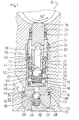
- a closure part 68 On the displacement space side is a closure part 68, which is in the form of a Has cylindrical plug, inserted into the cylinder bore 12 and through a caulking 70 is fastened and sealed in a fluid-tight manner in the pump housing 14.
- the closure part 68 also holds the liner 26 in the cylinder bore 12.
- the closure part 68 is connected to the bushing 26 via a snap connection connected:
- the liner 26 has a 64 on its liner bottom Radial collar 72, which has an undercut 74 on its closure part 68 forms the opposite side.
- the liner 26 is 64 with its liner bottom in a cylindrical recess 76 in one of the liner 26 facing End face of the closure member 68 inserted.
- the radial collar 72 am Liner base 64 is located within a hollow cylindrical rim 78 of the closure member 68 which surrounds the cylindrical recess 76.
- the closure part 68 can be machined or non-machined, for example Cold blows are made.
- the snap nipples 80 can be manufactured of the hollow cylindrical edge 78 of the closure part 68 by axial pressing one not shown, hereinafter referred to as the bell Forming tool are produced, which has the hollow cylindrical edge 78th engages and has three inwardly projecting cams, which the Form snap nipples 80. No counter tool is required for this holds the hollow cylindrical rim 78 from the inside.
- Another way to make the snap nipples 80 is not one insert stamp shown in the cylindrical recess 76, which to the snap nipples 80 complementary recesses on its circumference having.
- the snap nipples 80 are, for example, in these recesses deformed by means of the bell described in the previous paragraph. To The bell can be pulled off due to the elasticity of the Pull the hollow cylindrical edge 78 out of the cylindrical recess 76.
- This type of manufacture of the snap nipples 80 has in the manufacture of the Closure part 68 by reshaping the advantage that the snap nipples 80 in one operation can be produced together with the closure part 68.
- the described stamp, which is inserted into the cylindrical recess 76 is in in this case part of a multi-part forming tool, not shown.
- the Stamp forms the recess 76 and preferably also the blind hole 84 a stamp extension.
- connection of the closure part 68 with the liner 26 takes place before Insert into the pump housing 14.
- the connection of the closure part 68 with the bushing 26 creates an easy-to-handle preassembly.
- the Connection of the closure member 68 with the liner 26 comes only to Inserting these two parts into the pump housing 14 is important because Liner 26 and closure member 68 after insertion into and caulking held together in the pump housing 14 by the pump housing 14 and aligned with each other.
- a check valve as an outlet valve 86 is housed, which cooperates with a conical valve seat 88, which at a closure part 68 facing the opening of the center hole 66 in Bushing bottom 64 is attached.
- a valve ball 90 is used as a valve closing body, which of a Helical compression spring as valve closing spring 92 pressed against the valve seat 88 becomes.
- a radial groove 94 is in the base of the cylindrical recess 76 as the pump outlet of the closure member 68, which into which the exhaust valve 86th receiving blind hole 84 opens and through the hollow cylindrical edge 78 of Closure part 68 passes.
- the radial groove 94 communicates via a Annular channel 96 with an outlet bore 98 made in the pump housing 14.
- the snap nipples 80 on the relatively thin edge 78 result in a radial Considered direction, a between the bushing 26 and the closure member 68 certain elasticity, so that when installing the liner 26 together with the Closure part 68 in the pump housing 14 is never entirely avoidable Misalignments can be easily compensated.
Landscapes
- Engineering & Computer Science (AREA)
- Mechanical Engineering (AREA)
- General Engineering & Computer Science (AREA)
- Physics & Mathematics (AREA)
- Fluid Mechanics (AREA)
- Transportation (AREA)
- Details Of Reciprocating Pumps (AREA)
Description
- Figur 1
- einen Achsschnitt einer erfindungsgemäßen Kolbenpumpe; und
- Figur 2
- einen Achsschnitt eines Verschlußteils der erfindungsgemäßen Kolbenpumpe in größerem Maßstab.
Claims (6)
- Kolbenpumpe (10) mit einem zu einer hin- und hergehenden Hubbewegung antreibbaren Kolben (16), der axial verschieblich in einer Laufbuchse (26) aufgenommen ist, die in ein Pumpengehäuse (14) einsetzbar ist, und mit einem Verschlußteil (68), das das Pumpengehäuse (14) druckdicht verschließend auf einer Stirnseite der Laufbuchse (26) in das Pumpengehäuse (14) einsetzbar ist, dadurch gekennzeichnet, daß das Verschlußteil (68) mittels einer Schnapp- oder Rastverbindung (72, 74, 80) mit der Laufbuchse (26) verbunden ist.
- Kolbenpumpe nach Anspruch 1, dadurch gekennzeichnet, daß die Laufbuchse (26) eine Hinterschneidung (74) aufweist, die von einem Rand (78) des Verschlußteils (68) hintergriffen wird.
- Kolbenpumpe nach Anspruch 2, dadurch gekennzeichnet, daß der Rand (78) des Verschlußteils (68) mindestens eine Schnapp- oder Rastwarze (80) aufweist, die die Hinterschneidung (74) der Laufbuchse (26) hintergreift.
- Kolbenpumpe nach Anspruch 2, dadurch gekennzeichnet, daß der Rand (78) des Verschlußteils (68) eine umlaufende Schnapp- oder Rastsicke aufweist, die die Hinterschneidung (74) der Laufbuchse (26) hintergreift.
- Kolbenpumpe nach Anspruch 1, dadurch gekennzeichnet, daß in das Verschlußteil (68) ein Rückschlagventil (86) eingesetzt ist.
- Kolbenpumpe nach Anspruch 5, dadurch gekennzeichnet, daß die Laufbuchse (26) einen Laufbuchsenboden (64) mit einem Durchgangsloch (66) aufweist, an dessen verschlußteilseitiger Mündung ein Ventilsitz (88) für das Rückschlagventil (86) ausgebildet ist.
Applications Claiming Priority (3)
| Application Number | Priority Date | Filing Date | Title |
|---|---|---|---|
| DE19732818A DE19732818A1 (de) | 1997-07-30 | 1997-07-30 | Kolbenpumpe |
| DE19732818 | 1997-07-30 | ||
| PCT/DE1998/001672 WO1999006708A1 (de) | 1997-07-30 | 1998-06-18 | Kolbenpumpe |
Publications (2)
| Publication Number | Publication Date |
|---|---|
| EP0935712A1 EP0935712A1 (de) | 1999-08-18 |
| EP0935712B1 true EP0935712B1 (de) | 2003-02-26 |
Family
ID=7837376
Family Applications (1)
| Application Number | Title | Priority Date | Filing Date |
|---|---|---|---|
| EP98936215A Expired - Lifetime EP0935712B1 (de) | 1997-07-30 | 1998-06-18 | Kolbenpumpe |
Country Status (5)
| Country | Link |
|---|---|
| US (1) | US6361295B2 (de) |
| EP (1) | EP0935712B1 (de) |
| JP (1) | JP2001501280A (de) |
| DE (2) | DE19732818A1 (de) |
| WO (1) | WO1999006708A1 (de) |
Families Citing this family (20)
| Publication number | Priority date | Publication date | Assignee | Title |
|---|---|---|---|---|
| DE19914065A1 (de) * | 1999-03-27 | 2000-09-28 | Bosch Gmbh Robert | Kolbenpumpe |
| DE19928913A1 (de) * | 1999-06-24 | 2001-01-04 | Bosch Gmbh Robert | Kolbenpumpe |
| US6792968B1 (en) * | 2000-05-30 | 2004-09-21 | Robert H. Breeden | Pump assembly and method |
| US20050152363A1 (en) * | 2000-12-21 | 2005-07-14 | Bellsouth Intellectual Property Corporation | Disposable communications addresses |
| US6589032B2 (en) * | 2001-07-13 | 2003-07-08 | Delphi Technologies, Inc. | Pump and pump piston assembly |
| US7785086B2 (en) * | 2002-09-24 | 2010-08-31 | Continental Teves Ag & Co. Ohg | Supply device |
| DE10249909A1 (de) * | 2002-10-26 | 2004-05-06 | Continental Teves Ag & Co. Ohg | Kolbenpumpe |
| US20070041850A1 (en) * | 2005-08-19 | 2007-02-22 | Kelsey-Hayes Company | Multi-piston pump and valve arrangement |
| JP4857731B2 (ja) * | 2005-11-24 | 2012-01-18 | 株式会社アドヴィックス | 車両用ブレーキ装置 |
| DE102006029368A1 (de) * | 2006-06-27 | 2008-01-03 | Robert Bosch Gmbh | Kolbenpumpe für ein Fahrzeugbremssystem mit einem Dichtelement |
| DE102006048903B4 (de) * | 2006-10-17 | 2025-08-07 | Robert Bosch Gmbh | Pumpe für ein Fahrzeugbremssystem mit einem Ventil |
| JP5034705B2 (ja) * | 2007-06-18 | 2012-09-26 | 株式会社アドヴィックス | ピストンポンプ |
| US20090057345A1 (en) * | 2007-08-31 | 2009-03-05 | Dukes Stephen A | Fluid dispenser |
| USD592899S1 (en) | 2008-04-25 | 2009-05-26 | Impact Products Llc | Soap dispenser |
| US10730496B2 (en) * | 2014-04-10 | 2020-08-04 | Robert Bosch Gmbh | Hydraulic unit |
| DE102014212292A1 (de) * | 2014-06-26 | 2015-12-31 | Robert Bosch Gmbh | Auslassventil mit einem Aufnahmeelement |
| KR20160113497A (ko) * | 2015-03-21 | 2016-09-29 | 주식회사 만도 | 전동식 일체형 유압 브레이크 장치의 펌프 |
| CN108150373B (zh) * | 2017-12-22 | 2019-06-07 | 赛克思液压科技股份有限公司 | 一种闭式液压泵的高度集成化后盖结构 |
| US11781541B2 (en) * | 2021-09-29 | 2023-10-10 | Chipmast Autotronix Co., Ltd. | Oil-scavenge pump and method for assembling the same |
| US11668291B2 (en) * | 2021-09-29 | 2023-06-06 | Chipmast Autotronix Co., Ltd. | Oil-scavenge pump and method for assembling the same |
Family Cites Families (12)
| Publication number | Priority date | Publication date | Assignee | Title |
|---|---|---|---|---|
| US3596822A (en) * | 1969-05-21 | 1971-08-03 | Holley Plastics Co | Package structure |
| AU473793B2 (en) * | 1973-06-26 | 1975-01-09 | Precision Valve Australia Pty. Limited | Pump with slide valve |
| DE3644596A1 (de) * | 1986-12-29 | 1988-07-07 | Bosch Gmbh Robert | Druckentlastungsventil fuer kraftstoffeinspritzpumpen |
| DE4028941A1 (de) * | 1990-03-03 | 1991-09-05 | Bosch Gmbh Robert | Druckmittelfoerdereinrichtung mit einer hubkolbenpumpe |
| DE4027794C2 (de) | 1990-09-01 | 2002-06-20 | Continental Teves Ag & Co Ohg | Hydraulische Radialkolbenpumpe |
| DE4136590A1 (de) * | 1991-11-07 | 1993-05-13 | Bosch Gmbh Robert | Pumpe |
| DE4243667A1 (de) * | 1992-12-23 | 1994-06-30 | Bosch Gmbh Robert | Pumpe für ein hydraulisches System |
| DE59402095D1 (de) * | 1993-07-23 | 1997-04-17 | Teves Gmbh Alfred | Hydraulische bremsanlage mit bremsschlupf- und antriebsschlupfregelung |
| DE4426945A1 (de) * | 1994-07-29 | 1996-02-01 | Bosch Gmbh Robert | Kolbenpumpe |
| DE19503945A1 (de) * | 1995-02-07 | 1996-08-08 | Bosch Gmbh Robert | Federbelastetes Rückschlagventil |
| JPH1030576A (ja) * | 1996-07-18 | 1998-02-03 | Unisia Jecs Corp | プランジャポンプ |
| DE59708191D1 (de) * | 1996-09-19 | 2002-10-17 | Bosch Gmbh Robert | Kolbenpumpe |
-
1997
- 1997-07-30 DE DE19732818A patent/DE19732818A1/de not_active Withdrawn
-
1998
- 1998-06-18 EP EP98936215A patent/EP0935712B1/de not_active Expired - Lifetime
- 1998-06-18 JP JP11510351A patent/JP2001501280A/ja active Pending
- 1998-06-18 WO PCT/DE1998/001672 patent/WO1999006708A1/de not_active Ceased
- 1998-06-18 DE DE59807309T patent/DE59807309D1/de not_active Expired - Lifetime
- 1998-06-18 US US09/269,559 patent/US6361295B2/en not_active Expired - Fee Related
Also Published As
| Publication number | Publication date |
|---|---|
| US6361295B2 (en) | 2002-03-26 |
| DE59807309D1 (de) | 2003-04-03 |
| WO1999006708A1 (de) | 1999-02-11 |
| US20010016171A1 (en) | 2001-08-23 |
| DE19732818A1 (de) | 1999-02-04 |
| JP2001501280A (ja) | 2001-01-30 |
| EP0935712A1 (de) | 1999-08-18 |
Similar Documents
| Publication | Publication Date | Title |
|---|---|---|
| EP0935712B1 (de) | Kolbenpumpe | |
| EP0961882B1 (de) | Kolbenpumpe | |
| EP1108141B1 (de) | Kolbenpumpe | |
| DE19732817B4 (de) | Kolbenpumpe | |
| EP1101035A1 (de) | Kolbenpumpe | |
| EP0932762B1 (de) | Rohrförmiger kolben und verschlusstopfen für eine radialkolbenpumpe, hergestellt durch kaltumformen | |
| EP1185794B1 (de) | Kolbenpumpe | |
| EP0931218A1 (de) | Kolbenpumpe mit einem an der laufbuchse angebrachten filterelement | |
| EP0932766A1 (de) | Kolbenpumpe | |
| DE19750851A1 (de) | Kolbenpumpe | |
| EP0932760B1 (de) | Verliersicherung für einen kolben einer radialkolbenpumpe | |
| DE19902018A1 (de) | Kolbenpumpe | |
| EP0932765B1 (de) | Kolbenpumpe | |
| EP1090228A1 (de) | Kolbenpumpe | |
| DE19742611A1 (de) | Kolbenpumpe | |
| DE19902019A1 (de) | Kolbenpumpe | |
| EP1030974A1 (de) | Filteranordnung in der einlasskammer einer kolbenpumpe | |
| DE19732747A1 (de) | Rückschlagventil, insbesondere für eine Kolbenpumpe | |
| DE19918126A1 (de) | Kolbenpumpe | |
| WO2000006905A1 (de) | Kolbenpumpe | |
| DE19732748A1 (de) | Kolbenpumpe | |
| DE19905790A1 (de) | Kolbenpumpe |
Legal Events
| Date | Code | Title | Description |
|---|---|---|---|
| PUAI | Public reference made under article 153(3) epc to a published international application that has entered the european phase |
Free format text: ORIGINAL CODE: 0009012 |
|
| AK | Designated contracting states |
Kind code of ref document: A1 Designated state(s): DE FR GB |
|
| 17P | Request for examination filed |
Effective date: 19990811 |
|
| GRAH | Despatch of communication of intention to grant a patent |
Free format text: ORIGINAL CODE: EPIDOS IGRA |
|
| GRAH | Despatch of communication of intention to grant a patent |
Free format text: ORIGINAL CODE: EPIDOS IGRA |
|
| GRAA | (expected) grant |
Free format text: ORIGINAL CODE: 0009210 |
|
| AK | Designated contracting states |
Designated state(s): DE FR GB |
|
| REG | Reference to a national code |
Ref country code: GB Ref legal event code: FG4D Free format text: NOT ENGLISH |
|
| REF | Corresponds to: |
Ref document number: 59807309 Country of ref document: DE Date of ref document: 20030403 Kind code of ref document: P |
|
| GBT | Gb: translation of ep patent filed (gb section 77(6)(a)/1977) | ||
| ET | Fr: translation filed | ||
| PLBE | No opposition filed within time limit |
Free format text: ORIGINAL CODE: 0009261 |
|
| STAA | Information on the status of an ep patent application or granted ep patent |
Free format text: STATUS: NO OPPOSITION FILED WITHIN TIME LIMIT |
|
| 26N | No opposition filed |
Effective date: 20031127 |
|
| PGFP | Annual fee paid to national office [announced via postgrant information from national office to epo] |
Ref country code: GB Payment date: 20090623 Year of fee payment: 12 |
|
| GBPC | Gb: european patent ceased through non-payment of renewal fee |
Effective date: 20100618 |
|
| PG25 | Lapsed in a contracting state [announced via postgrant information from national office to epo] |
Ref country code: GB Free format text: LAPSE BECAUSE OF NON-PAYMENT OF DUE FEES Effective date: 20100618 |
|
| PGFP | Annual fee paid to national office [announced via postgrant information from national office to epo] |
Ref country code: FR Payment date: 20130703 Year of fee payment: 16 |
|
| REG | Reference to a national code |
Ref country code: FR Ref legal event code: ST Effective date: 20150227 |
|
| PG25 | Lapsed in a contracting state [announced via postgrant information from national office to epo] |
Ref country code: FR Free format text: LAPSE BECAUSE OF NON-PAYMENT OF DUE FEES Effective date: 20140630 |
|
| PGFP | Annual fee paid to national office [announced via postgrant information from national office to epo] |
Ref country code: DE Payment date: 20160810 Year of fee payment: 19 |
|
| REG | Reference to a national code |
Ref country code: DE Ref legal event code: R119 Ref document number: 59807309 Country of ref document: DE |
|
| PG25 | Lapsed in a contracting state [announced via postgrant information from national office to epo] |
Ref country code: DE Free format text: LAPSE BECAUSE OF NON-PAYMENT OF DUE FEES Effective date: 20180103 |