EP0936003A2 - Un élément de cadre structural - Google Patents
Un élément de cadre structural Download PDFInfo
- Publication number
- EP0936003A2 EP0936003A2 EP98308650A EP98308650A EP0936003A2 EP 0936003 A2 EP0936003 A2 EP 0936003A2 EP 98308650 A EP98308650 A EP 98308650A EP 98308650 A EP98308650 A EP 98308650A EP 0936003 A2 EP0936003 A2 EP 0936003A2
- Authority
- EP
- European Patent Office
- Prior art keywords
- socket
- wall
- hollow body
- strut
- side wall
- Prior art date
- Legal status (The legal status is an assumption and is not a legal conclusion. Google has not performed a legal analysis and makes no representation as to the accuracy of the status listed.)
- Withdrawn
Links
Images

Classifications
-
- B—PERFORMING OPERATIONS; TRANSPORTING
- B62—LAND VEHICLES FOR TRAVELLING OTHERWISE THAN ON RAILS
- B62D—MOTOR VEHICLES; TRAILERS
- B62D27/00—Connections between superstructure or understructure sub-units
- B62D27/02—Connections between superstructure or understructure sub-units rigid
- B62D27/023—Assembly of structural joints
-
- B—PERFORMING OPERATIONS; TRANSPORTING
- B21—MECHANICAL METAL-WORKING WITHOUT ESSENTIALLY REMOVING MATERIAL; PUNCHING METAL
- B21C—MANUFACTURE OF METAL SHEETS, WIRE, RODS, TUBES, PROFILES OR LIKE SEMI-MANUFACTURED PRODUCTS OTHERWISE THAN BY ROLLING; AUXILIARY OPERATIONS USED IN CONNECTION WITH METAL-WORKING WITHOUT ESSENTIALLY REMOVING MATERIAL
- B21C37/00—Manufacture of metal sheets, rods, wire, tubes, profiles or like semi-manufactured products, not otherwise provided for; Manufacture of tubes of special shape
- B21C37/06—Manufacture of metal sheets, rods, wire, tubes, profiles or like semi-manufactured products, not otherwise provided for; Manufacture of tubes of special shape of tubes or metal hoses; Combined procedures for making tubes, e.g. for making multi-wall tubes
- B21C37/15—Making tubes of special shape; Making tube fittings
- B21C37/28—Making tube fittings for connecting pipes, e.g. U-pieces
- B21C37/29—Making branched pieces, e.g. T-pieces
- B21C37/294—Forming collars by compressing a fluid or a yieldable or resilient mass in the tube
-
- B—PERFORMING OPERATIONS; TRANSPORTING
- B62—LAND VEHICLES FOR TRAVELLING OTHERWISE THAN ON RAILS
- B62D—MOTOR VEHICLES; TRAILERS
- B62D23/00—Combined superstructure and frame, i.e. monocoque constructions
- B62D23/005—Combined superstructure and frame, i.e. monocoque constructions with integrated chassis in the whole shell, e.g. meshwork, tubes, or the like
Definitions
- the present invention relates to a structural frame element, in particular but not exclusively, for the construction of space frames.
- the invention also relates to a process of constructing space frame from such elements.
- a structural frame element for the construction of space frames is known from DE 4228238.
- the known structural frame element is hollow and elongate and is provided with connection nodes located at predetermined positions along its length, the connection nodes being in the form of laterally outwardly extending projections.
- connection nodes located at predetermined positions along its length, the connection nodes being in the form of laterally outwardly extending projections.
- connection between the strut and node projection is similar to a male and female plug and sock connection wherein the male plug is defined by the node projection and the female socket is defined by the open end of the strut.
- the node projection In order to provide strength in the connection and to provide rigidity in the frame, it is desirable for the node projection to be a close fit inside the socket defined in the end of the strut and for the projection to extend as far as possible along the socket in order to provide a long support face in abutment with the inner wall of the socket: These criteria are difficult to achieve with the structural element of DE 4228238 since each node projection is formed by stretching the material of the element outwardly and so there is a limit to the amount of elongation of this material before it becomes too weak. In addition the forming process necessarily requires the transition zone between the node and wall of the structural member to be of a relative large radius and this necessarily reduces the effective length of the node projection.
- a structural flame element comprising an elongate hollow body having one or more strut connection nodes located along its length at predetermined positions, each connection node being in the form of a socket extending internally of the element, the socket comprising a socket wall depending from one side wall of the hollow body, the socket wall defining a socket recess and being formed by hydro-forming from said one side wall of the hollow body.
- a space frame including at least two elongate structural frame elements arranged side by side and being interconnected by a plurality of elongate struts spaced along the length of the elements, each structural frame element comprising an elongate hollow body having one or more strut connection nodes located along its length at predetermined positions, each connection node being in the form of a socket extending internally of the element, the socket comprising a socket wall depending from one side wall of the hollow body, the socket wall defining a socket recess and being formed by hydro-forming from said one side wall of the hollow body, each opposite end of each strut being in the form of a plug received within the socket defined by a co-operating respective connection node.
- the term 'hydro-forming' includes any forming process which utilises a pressurised hydraulic fluid for deforming an element;
- the pressurised hydraulic fluid may be a solid such as small solid balls which collectively act as a fluid; a liquid such as a suitable oil; or a gas such as steam.
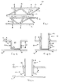
- a space frame 10 comprising four structural frame elements 12 extending side by side and being joined together by a plurality of connection struts 14.
- the struts 14 are spaced along the length of the structural elements 12 and each strut 14 is connected to a respective pair of elements 12 at node locations 16 spaced at predetermined positions and angles along the length of the elements 12.
- the frame 10 shown in Figure 1 is of box-like form and is of a type as used as a space frame in the manufacture of vehicles.
- the space frame be light in weight and as rigid as possible.
- the elements 12 and struts 14 comprise elongate hollow bodies 17,19 respectively of predetermined wall thickness S 1 formed from a suitable structural material.
- the structural material is a metal such as steel, aluminium or aluminium alloy. It will be appreciated that the elements 12 and struts 14 may be of the same material or of a different material.
- connection between the end of a strut 14 and the respective element 12 at each node location 16 is defined by a plug and socket type connection 18.
- each element 12 at each node location 16 is provided with a socket 20 which extends internally of the body 17 of the element 12.
- the socket 20 is formed by hydro-forming so as to have a socket wall 21 which over the depth D of the socket 20 defines a socket recess 23 which in cross sectional shape and dimensions is substantially constant throughout its depth D.
- the cross-sectional shape and dimensions of the socket recess 23 are chosen to be substantially the same as the external cross-sectional shape and dimensions of the end of the co-operating strut 14 such that the end portion of the strut forms a close fitting plug 27.
- the socket 20 would be formed by a hydro-forming technique. This is preferably done inwardly deforming the wall of body 17 whilst the body 17 is filled with a pressurised fluid. Inward deformation is achieved using an appropriate pressing tool such as a punch and due to the support given by the pressurised fluid it is possible to control the shaping process to close tolerances and create radii R 1 and R 2 which are of relatively small dimensions; R 1 being the radius at the transition zone between the outer wall of body 17 and the socket wall 21 and R 2 being the radius of the transition zone between the bottom wall 29 of the socket and socket wall 21.
- the radii R 1 and R 2 being of small dimension is particularly advantageous as it maximises the depth D for the socket over which the recess is of constant cross section.
- the hydraulic fluid may be hot in order to facilitate the forming process, viz the hotter the fluid the easier it is to deform the material of the wall of body 17.
- By increasing the pressure of the hydraulic fluid it is possible to obtain a smaller radii R 1 or R 2 .
- the pressure of the hydraulic fluid and/or its temperature are chosen such that the radii R 1 and R 2 fall with the range of 1 to 4 times the wall thickness S 1 , viz S 1 ⁇ R 1 ,R 2 ⁇ 4(S 1 ).
- the depth D of the recess is chosen to be as long as possible in order to provide face to face contact between the plug and socket over as great an axial distance as possible.
- the maximum length is determined by the elongation ratio of the material from which body 17 is made and so the length should not exceed this ratio otherwise the socket wall 21 would become too weak and the rigidity of the joint would be compromised. It will be appreciated that the elongation ratio is dependent upon the temperature of the hydraulic fluid and so it is envisaged that recesses of longer length may be achieved using fluid at elevated temperatures.
- the bottom of the socket recess may be open as shown in Figure 4 so as to permit the plug to enter deeper internally of the element 12.
- Such an arrangement is particularly advantageous when using materials having a small elongation ratio.
- the terminal end of the socket wall 21 is spaced from the opposed side wall of the body 17. This is advantageous as it prevents the terminal end of the socket wall 21 from rubbing against the opposed side wall and thereby avoids vibration noise and possible wear damage to the opposed wall.
- the socket wall 21 is extended so as to be fixedly secured to the opposed side wall of the element 12.
- the bottom wall 29 and adjacent portion of socket wall 21 are received within a recess 71 formed in the opposed side wall.
- the recess 71 is preferably formed simultaneously during the hydro-forming process by the tool (not shown) responsible for forming the socket 20.
- the bottom wall 72 of recess 71 and bottom wall 29 are removed to leave the terminal end of the socket 20 open ended and located within an opening formed by the removal of bottom wall 72.
- the terminal end of the socket 20 is secured against lateral movement and so provides a socket 20 of increased rigidity.
- embodiment 80 ( Figure 8) a similar effect for providing increased rigidity is achieved by the provision of an additional projection 81 which engages with the terminal end of the strut 14.
- element 12 is formed with a socket 20 in a manner similar to that shown in Figure 4.
- the projection 81 is located co-axially relative to the socket 20 and extends from the opposed wall of element 12 to project internally of the terminal end of strut 14.
- the projection 81 is formed so as to have a shape which engages with the internal wall of the strut 14 and thereby prevent lateral displacement of the strut 14.
- the projection 81 is preferably formed by hydro-forming techniques.
- each strut 14 is preferably secured to the co-operating element 12 by welding 35 which preferably extends continuously around the periphery of the strut 14 adjacent to the mouth of recess 23 and so forms a weld connection between the strut 14 and the external marginal portion of the element 12 which surrounds the socket 20.
- transition zone of radius R 1 provides a lead-into the recess 23, it facilitates insertion of the strut into the recess 23 and also defines with the external wall of the strut 14, a wide mouthed welding recess which facilitates the production of a strong weld connection. It is envisaged that the strut 14 may be secured to the element 12 by other forms of bonding as an alternative to welding.
- a space frame maybe constructed by the provision of a shallow socket 20 in those cases where a strongly rigid connection between the struts 14 and elements 12 is not necessary.
- a space frame 100 is shown by way of example in Figure 5. With such a space frame 100 the sockets 20 primarily act as positional location for the struts 14 and do not co-operate therewith to provide significant lateral support.
Landscapes
- Engineering & Computer Science (AREA)
- Mechanical Engineering (AREA)
- Chemical & Material Sciences (AREA)
- Combustion & Propulsion (AREA)
- Transportation (AREA)
- Body Structure For Vehicles (AREA)
- Mutual Connection Of Rods And Tubes (AREA)
Applications Claiming Priority (3)
| Application Number | Priority Date | Filing Date | Title |
|---|---|---|---|
| GBGB9722182.4A GB9722182D0 (en) | 1997-10-22 | 1997-10-22 | A structural frame element |
| GB9722182 | 1997-10-22 | ||
| US09/298,050 US6205736B1 (en) | 1997-10-22 | 1999-04-22 | Structural frame element |
Publications (2)
| Publication Number | Publication Date |
|---|---|
| EP0936003A2 true EP0936003A2 (fr) | 1999-08-18 |
| EP0936003A3 EP0936003A3 (fr) | 2001-04-18 |
Family
ID=26312460
Family Applications (1)
| Application Number | Title | Priority Date | Filing Date |
|---|---|---|---|
| EP98308650A Withdrawn EP0936003A3 (fr) | 1997-10-22 | 1998-10-22 | Un élément de cadre structural |
Country Status (2)
| Country | Link |
|---|---|
| US (1) | US6205736B1 (fr) |
| EP (1) | EP0936003A3 (fr) |
Cited By (1)
| Publication number | Priority date | Publication date | Assignee | Title |
|---|---|---|---|---|
| WO2003059721A1 (fr) * | 2002-01-19 | 2003-07-24 | Thyssenkrupp Stahl Ag | Assemblage a noeud entre deux profiles creux d'une structure de cadre, notamment pour vehicules |
Families Citing this family (24)
| Publication number | Priority date | Publication date | Assignee | Title |
|---|---|---|---|---|
| US6623067B2 (en) * | 1997-10-16 | 2003-09-23 | Magna International Inc. | Door seal interface structure for a motor vehicle space frame |
| JP2004155219A (ja) * | 2002-11-01 | 2004-06-03 | Fuji Heavy Ind Ltd | 自動車の車体後部構造 |
| US20060137282A1 (en) * | 2002-12-19 | 2006-06-29 | Anvick Theodore E | Anvick aperture device and method of forming and using same |
| US20040187426A1 (en) * | 2003-03-31 | 2004-09-30 | Michael Callahan | Structures and components thereof |
| US7338400B2 (en) * | 2003-08-14 | 2008-03-04 | Johnson Controls Technology Company | Motor belt tensioning construction for an air handling unit |
| US7175202B2 (en) * | 2003-12-18 | 2007-02-13 | Fleetwood Enterprises, Inc. | Recreational vehicle chassis |
| US7210733B2 (en) * | 2004-04-22 | 2007-05-01 | Ford Global Technologies, Llc | Tubular support for shock tower in automobiles |
| US7275296B2 (en) * | 2004-10-29 | 2007-10-02 | Magna Structural Systems, Inc. | Method for forming a frame assembly |
| WO2006089421A1 (fr) * | 2005-02-23 | 2006-08-31 | Magna International Inc. | Structures d'assemblage pour longerons et traverses dans des cadres de chassis |
| US20060283129A1 (en) * | 2005-06-02 | 2006-12-21 | Larry Salhaney | Modular, structural, element, space frame or truss |
| US8484930B2 (en) * | 2005-11-01 | 2013-07-16 | Phillip C. Ruehl | Boxed frame member and method for manufacture |
| ATE477986T1 (de) * | 2006-02-01 | 2010-09-15 | Am General Llc | Längsträger |
| DE202006020844U1 (de) * | 2006-09-01 | 2010-08-12 | Audi Ag | Trägeranordnung für ein Fahrzeug |
| EP2957271A1 (fr) * | 2008-10-28 | 2015-12-23 | Darco Trust | Véhicule modulaire et son système de support en treillis triangulaire |
| KR100971736B1 (ko) * | 2009-04-03 | 2010-07-21 | 이재호 | 상하 각각 이중 앵커리지 기능을 갖는 전단보강재 |
| GB2477161B (en) * | 2010-01-26 | 2014-04-02 | Piers St John Spencer Galliard Cave | Loft flooring system |
| US9765520B2 (en) * | 2013-03-14 | 2017-09-19 | Scott F. Armbrust | Tubular joist structures and assemblies and methods of using |
| GB2516040A (en) * | 2013-07-08 | 2015-01-14 | Ecos Maclean Ltd | Structural Frame |
| US10072416B2 (en) | 2014-03-14 | 2018-09-11 | Scott F. Armbrust | Tubular joist structures and assemblies and methods of using |
| US9815145B2 (en) * | 2014-10-31 | 2017-11-14 | Bombardier Recreational Products Inc. | Frame assembly for a vehicle |
| US9751568B2 (en) * | 2015-12-07 | 2017-09-05 | Honda Motor Co., Ltd. | Body frame structure for a vehicle |
| CN106005023B (zh) * | 2016-05-24 | 2019-05-07 | 广州汽车集团股份有限公司 | 高刚性车身框架 |
| US11654975B2 (en) | 2020-12-21 | 2023-05-23 | Am General Llc | Vehicle frame rails and methods of assembling vehicle frame rails |
| US12365396B1 (en) | 2021-08-02 | 2025-07-22 | Am General Llc | Vehicle frame rails with swaged spacer connection and methods of manufacturing vehicle frame rails |
Family Cites Families (6)
| Publication number | Priority date | Publication date | Assignee | Title |
|---|---|---|---|---|
| US5285613A (en) * | 1992-01-31 | 1994-02-15 | Goldsworthy W Brandt | Pultruded joint system and tower structure made therewith |
| DE4228238C2 (de) * | 1992-08-25 | 1996-08-14 | Ges Innenhochdruckverfahren | Fachwerk mit Hohlteilen, Verfahren zu seiner Herstellung und seine Verwendung |
| DE4442150C2 (de) * | 1994-11-26 | 2001-01-25 | Benteler Werke Ag | Rohrförmiger Träger als Bestandteil eines Fahrwerks für ein Kraftfahrzeug |
| DE19530055B4 (de) * | 1995-08-16 | 2004-08-26 | Schuler Hydroforming Gmbh & Co. Kg | Verfahren zum Herstellen von doppelwandigen Durchbrechungen in Bauteilen nach dem Innenhochdruck-Umformverfahren |
| GB2316102B (en) * | 1996-08-09 | 2001-03-07 | Mark Eliott Fisher | Truss |
| US5720092A (en) * | 1996-08-21 | 1998-02-24 | General Motors Corporation | Method for hydroforming a vehicle space frame |
-
1998
- 1998-10-22 EP EP98308650A patent/EP0936003A3/fr not_active Withdrawn
-
1999
- 1999-04-22 US US09/298,050 patent/US6205736B1/en not_active Expired - Fee Related
Cited By (1)
| Publication number | Priority date | Publication date | Assignee | Title |
|---|---|---|---|---|
| WO2003059721A1 (fr) * | 2002-01-19 | 2003-07-24 | Thyssenkrupp Stahl Ag | Assemblage a noeud entre deux profiles creux d'une structure de cadre, notamment pour vehicules |
Also Published As
| Publication number | Publication date |
|---|---|
| US6205736B1 (en) | 2001-03-27 |
| EP0936003A3 (fr) | 2001-04-18 |
Similar Documents
| Publication | Publication Date | Title |
|---|---|---|
| US6205736B1 (en) | Structural frame element | |
| EP1327089B1 (fr) | Piston forge de maniere multiaxiale | |
| US4660269A (en) | Process for producing built-up camshafts | |
| EP0078551B1 (fr) | Tube et cadre pour une bicyclette | |
| JP2007533526A (ja) | 車両構成部品特に車台フレームの製造方法 | |
| KR19980081586A (ko) | 프레임 구조물 | |
| EP1268097B1 (fr) | Procede de fabrication d' un element tubulaire comprenant un composant de raccord hydroforme | |
| ITTO20001207A1 (it) | Procedimento per fissare almeno un cuscinetto in un alloggiamento e dispositivo a cuscinetto cosi' ottenuto. | |
| ITMI980428A1 (it) | Metodo per migliorare la resistenza a fatica dovuta ad una pressione ripetuta in corrispondenza della parte di un foro di diramazione in un | |
| CZ20021204A3 (cs) | Vyztužené hydraulicky lisované díly a způsoby jejich výroby | |
| CN1322299C (zh) | 制造加热器头部部件的方法和用这种方法制造的头部部件 | |
| US20080012302A1 (en) | Fitting and method for manufacturing a fitting | |
| US9869385B1 (en) | Powder metal net shape alignment feature | |
| CN104421261A (zh) | 装配单元和用于制造装配单元的方法 | |
| JP5360775B2 (ja) | 駆動クラッチ用クラッチリンクおよび製造方法 | |
| EP0112830B1 (fr) | Agencement de liaison pour des elements allonges d'echafaudage de construction ou autre | |
| KR100200997B1 (ko) | 충격식 앵커 | |
| KR0169184B1 (ko) | 가압 유체 완충 장치를 장착하기 위한 장착링 및 그 제조방법 | |
| JP3160647B2 (ja) | 完全な外部突出部を有する管状部材を製造する方法 | |
| EP1081022A3 (fr) | Méthode de fabrication de carrosserie et de chassis d'un véhicule | |
| PL173240B1 (pl) | Złącze rurowe z pierścieniem uszczelniającym | |
| JP4083613B2 (ja) | アクスルハウジング | |
| KR960041999A (ko) | 열 교환기용 유체 헤더의 관형 벽 제조 방법 | |
| JP2007501714A (ja) | 金属製管のプレス成形方法 | |
| JPH0435244B2 (fr) |
Legal Events
| Date | Code | Title | Description |
|---|---|---|---|
| PUAI | Public reference made under article 153(3) epc to a published international application that has entered the european phase |
Free format text: ORIGINAL CODE: 0009012 |
|
| AK | Designated contracting states |
Kind code of ref document: A2 Designated state(s): DE ES FR GB IT SE |
|
| AX | Request for extension of the european patent |
Free format text: AL;LT;LV;MK;RO;SI |
|
| RAP1 | Party data changed (applicant data changed or rights of an application transferred) |
Owner name: AMBORN, PETER, DR.-ING. Owner name: GKN SANKEY LIMITED |
|
| PUAL | Search report despatched |
Free format text: ORIGINAL CODE: 0009013 |
|
| AK | Designated contracting states |
Kind code of ref document: A3 Designated state(s): AT BE CH CY DE DK ES FI FR GB GR IE IT LI LU MC NL PT SE |
|
| AX | Request for extension of the european patent |
Free format text: AL;LT;LV;MK;RO;SI |
|
| RAP1 | Party data changed (applicant data changed or rights of an application transferred) |
Owner name: AMBORN, PETER, DR.-ING. Owner name: GKN AUTOSTRUCTURES LIMITED |
|
| 17P | Request for examination filed |
Effective date: 20011018 |
|
| AKX | Designation fees paid |
Free format text: DE ES FR GB IT SE |
|
| 17Q | First examination report despatched |
Effective date: 20040503 |
|
| GRAP | Despatch of communication of intention to grant a patent |
Free format text: ORIGINAL CODE: EPIDOSNIGR1 |
|
| RTI1 | Title (correction) |
Free format text: SPACE FRAME |
|
| STAA | Information on the status of an ep patent application or granted ep patent |
Free format text: STATUS: THE APPLICATION IS DEEMED TO BE WITHDRAWN |
|
| 18D | Application deemed to be withdrawn |
Effective date: 20060228 |