EP0112830B1 - Agencement de liaison pour des elements allonges d'echafaudage de construction ou autre - Google Patents
Agencement de liaison pour des elements allonges d'echafaudage de construction ou autre Download PDFInfo
- Publication number
- EP0112830B1 EP0112830B1 EP19830900452 EP83900452A EP0112830B1 EP 0112830 B1 EP0112830 B1 EP 0112830B1 EP 19830900452 EP19830900452 EP 19830900452 EP 83900452 A EP83900452 A EP 83900452A EP 0112830 B1 EP0112830 B1 EP 0112830B1
- Authority
- EP
- European Patent Office
- Prior art keywords
- joining
- component
- supporting members
- scaffolding
- female component
- Prior art date
- Legal status (The legal status is an assumption and is not a legal conclusion. Google has not performed a legal analysis and makes no representation as to the accuracy of the status listed.)
- Expired
Links
- 238000005304 joining Methods 0.000 title claims description 63
- 238000003780 insertion Methods 0.000 claims description 5
- 230000037431 insertion Effects 0.000 claims description 5
- 230000002093 peripheral effect Effects 0.000 claims 1
- 230000000994 depressogenic effect Effects 0.000 description 2
- 239000000463 material Substances 0.000 description 2
- 239000011505 plaster Substances 0.000 description 2
- 239000002699 waste material Substances 0.000 description 2
- 229910000831 Steel Inorganic materials 0.000 description 1
- 238000005452 bending Methods 0.000 description 1
- 230000008901 benefit Effects 0.000 description 1
- 230000015572 biosynthetic process Effects 0.000 description 1
- 230000008859 change Effects 0.000 description 1
- 230000007797 corrosion Effects 0.000 description 1
- 238000005260 corrosion Methods 0.000 description 1
- 230000008878 coupling Effects 0.000 description 1
- 238000010168 coupling process Methods 0.000 description 1
- 238000005859 coupling reaction Methods 0.000 description 1
- JEIPFZHSYJVQDO-UHFFFAOYSA-N iron(III) oxide Inorganic materials O=[Fe]O[Fe]=O JEIPFZHSYJVQDO-UHFFFAOYSA-N 0.000 description 1
- 238000004519 manufacturing process Methods 0.000 description 1
- 239000002184 metal Substances 0.000 description 1
- 238000003825 pressing Methods 0.000 description 1
- 230000009467 reduction Effects 0.000 description 1
- 239000011343 solid material Substances 0.000 description 1
- 239000010959 steel Substances 0.000 description 1
- 230000007704 transition Effects 0.000 description 1
- 238000003466 welding Methods 0.000 description 1
Images



Classifications
-
- E—FIXED CONSTRUCTIONS
- E04—BUILDING
- E04G—SCAFFOLDING; FORMS; SHUTTERING; BUILDING IMPLEMENTS OR AIDS, OR THEIR USE; HANDLING BUILDING MATERIALS ON THE SITE; REPAIRING, BREAKING-UP OR OTHER WORK ON EXISTING BUILDINGS
- E04G7/00—Connections between parts of the scaffold
- E04G7/30—Scaffolding bars or members with non-detachably fixed coupling elements
- E04G7/301—Scaffolding bars or members with non-detachably fixed coupling elements for connecting bars or members which are parallel or in end-to-end relation
Definitions
- the present invention relates to a joining arrangement for extended scaffolding elements in a building scaffolding or similar, which is so arranged as to join one end of one scaffolding element facing towards one end of the second scaffolding element with a first part of the joining arrangement forming a female component and a second part of the joining arrangement forming a male component, which in the joined state extends inside the female component, whereby the female component and the male component exhibit joining surfaces extending essentially concentrically with one another and facing towards one another.
- Prior-art joining arrangements for extended scaffolding elements in the form of sleeves or pins are attached to one or both ends of a scaffolding element and are intended to interact with one end of another scaffolding element in such a way that the latter end is introduced into the sleeve or is slid over the pin.
- a scaffolding element In order to produce the necessary stability in the joint, it has been necessary until now in prior-art arrangements to design the sleeve or the pin with a cross-section such that it does not deviate excessively from the corresponding dimension of the end with which it interacts. The presence of excessive clearance between the joining surfaces will, in fact, produce free play of such magnitude as to render the stability of the scaffolding inadequate.
- the patent specification EP A10 004 806 shows a joining device for scaffolding elements.
- This known device shows a male component in the shape of an especially designed end of one of the scaffolding elements, and a female component in the shape of an especially shaped end of the other scaffolding element.
- the known device has in certain sections a cross-sectional shape, where depressed portions are present in the male component as well as in the female component, in which case there is substantially no play between male component and female component.
- By means of the depressed portions of the known device there is obtained a relatively stable joint, which does not allow any rotational movement between the scaffolding elements.
- the female component has also had to be provided with a flanging in its insertion end in order to facilitate the insertion of the male component.
- the object of the present invention is to eliminate the aforementioned shortcommings and to propose a joining arrangement which possesses stability and which at the same time is easy to erect and dismantle.
- a joining arrangement in accordance with the present invention, which is characterized in that said joining surfaces are so dimensioned as to cause a space to be formed between them, and in that only one of said joining surfaces exhibits at least one set of at least three pheripheral, symmetrically positioned and radially facing local portions projecting from said joining surface which form load-bearing supporting members located at a certain distance from one another for the opposing joining surface and located in such a way that the female component exhibits an essentially cylindrical jacket-shaped insertion end and locates the male component so that said space is defined uniformly around substantially the entire joining surface of the male component.
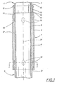
- Fig. 1 shows a partially interrupted view of a central longitudinal section through the joining arrangement along the line I-I in Fig. 2 in a first embodiment
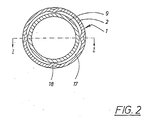
- Fig. 2 is a section along the line II-II through the joining arrangement shown in Fig. 1
- Fig. 3 is a partially sectioned view of the joining arrangement in a second embodiment
- Fig. 4 is a partially sectioned view of the joining arrangement in a third embodiment.
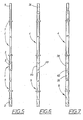
- Figs. 5 and 6 show examples of scaffolding elements having joining arrangements in accordance with the first and second embodiments
- Fig. 7 shows a scaffolding element having a joining arrangement in accordance with a fourth embodiment
- Fig. 8 shows an example of a building scaffolding having joining arrangements in accordance with the invention.
- the joining arrangement 1 in accordance with the invention consists in the case of the first embodiment shown in Figs. 1 and 2 of a sleeve component 2 which is securely attached to one end 3 of an extended scaffolding element 4.
- Fig. 5 shows an example of two scaffolding elements 4, 5 which are connected together by means of the joining arrangement 1 in accordance with the first typical embodiment.
- the two scaffolding elements 4, 5 are in the form of uprights forming part of a building scaffolding shown in a typical example in Fig. 8.
- the Figure does not show any platforms, etc., which are usually supported by certain of the horizontal scaffolding elements 6 of the building scaffolding.
- Each upright 4, 5 also has distributed over its length a number of cup-shaped coupling elements 7 intended to accept the horizontal scaffolding elements 6, 8 of the building scaffolding.
- both the scaffolding elements 4, 5 shown here i.e. the uprights in the examples shown, are provided at their lower ends 3 with the sleeve component 2, whereas their upper end 9 is'entirely bare and is intended to be inserted into the sleeve component 2.
- the two uprights 4, 5 shown by way of example are designed to be of identical diameter and have end surfaces 10, 11 which, once the arrangement has been assembled, provide support for each other.
- the sleeve component 2 thus forms a female component, whilst one end 9 of the upright 5 forms a male component which extends into the female component through the opening 12 at its end.
- the sleeve component 2 is executed in the form of a length of tube of strong metal, for example steel, and the uprights 4, 5 may be executed in the same material.
- the sleeve component 2 has a significantly greater transverse dimension than the uprights 4, 5 and is executed with circular cross-section in the example shown, as may be appreciated from Fig. 2.
- the sleeve component is provided with an annular impressed area 14 which is in contact with the periphery of the upright 4.
- the annular impressed area 14 then becomes a conical edge 15, thereby providing the space for a welding run 16 to hold the sleeve component securely to the end 3 of the upright 4.
- the sleeve component 2 has a transverse dimension such that a clear space 17 is formed between the sleeve component and the upper end 9 of the upright 5.
- the sleeve component 2 also has two sets of local impressed areas 18, 19, of which one outer set of impressed areas 18 is situated at the opening 12 at the outer end of the sleeve component and at a short distance from it, and the second, inner set of impressed areas 19 is situated close to the inner end 13 of the sleeve component.
- the impressed areas are four in number in the example shown and are produced by local deformation of the wall of the sleeve component, achieved by the use of a .
- the local impressed areas 18, 19 are distributed around the periphery of the sleeve component 2 and are also of identical size in the example shown in Fig. 1 and Fig. 2.
- the impressed areas 18, 19 are shown to be of slightly oval shape, thereby ensuring that they extend for a greater distance in the longitudinal sense of the sleeve component 2 than in its transverse sense, resulting in the smallest possible distance in the transverse sense of the sleeve component in relation to the size of the impressed areas.
- This provides the greatest possible free space 17 between the impressed areas, as may be appreciated from Fig. 2, thereby providing space for particules of dirt and waste plaster and similar.
- the supporting surfaces 20 of all the impressed areas 18, 19 are situated at the same relative radial distance from the longitudinal axis 37 of the sleeve component 2.
- the impressed areas 18, 19 form supporting members to provide support for the male component in the joining member, i.e. the upper end 9 of the upright 5 in the example shown in Fig. 1 and 2.
- This end 9 by which is meant the entire part which is introduced into the sleeve component 2, is cylinder jacket-shaped in the first example shown and forms a joining surface or supporting surface against which the impressed areas 18, 19 are intended to provide support for an outer part, thus forming the supporting surface 20.
- Point contact should be achieved theoretically, although in practice the contact extends over a surface of a certain area due to a certain amount of deformation and wear in the course of using the joining arrangement.
- the impressed areas 18, 19 are so dimensioned in relation to the transverse dimension of the male component as to provide a certain small amount of free play between the supporting surfaces 20 of the impressed areas and the supporting surface 21 of the maie component 9. This free play is necessary in order to provide certain manufacturing tolerances and in order to permit the insertion and withdrawal of the male component. This means in practice, as shown in the drawings, that when under load contact will be achieved only against certain of the impressed areas 18, 19.
- the end 9 of the upright 5 will be able easily to be inserted into the opening 12 at the end of the sleeve component 2, which has an internal diameter which exceeds by a considerable amount the external diameter of the end 9 of the upright, at the same time as the smallest possible amount of free play is provided between the supporting surfaces 20, 21.
- the female component consists instead of the end 22 of the upper support 4, whereas the male component is formed by a pin component 24 permanently attached to the upper end 23 of the lower upright 5.
- the end 22 of the upright 4 is provided with impressed areas 23 which, in'the case of this particular embodiment, are in the form of only a single set of four impressed areas.
- the pin component 24 is, in fact, slightly tapered in the direction of its free end 25, whereby the impressed areas 23 are situated in proximity to said end.
- the transverse dimension i.e.
- the diameter, of the pin component 24 provides a fit at its point of fixing to the end 23 of the upright 5 and thus on a level with the edge part 25 of the upright 4 such that only a small amount of free play is present between the pin component 24 and said edge part 25 in the assembled state.
- a corresponding amount of free play is provided substantially between the supporting surface 27 of the impressed areas 23 and the outer surface 28 of the pin component 24.
- the third embodiment illustrated in Fig. 4 is similarly executed with a male component in the form of a pin component 29 and a female component in the form of the lower end 30 of the upper upright.
- the pin component 29 is, however, cylinder jacket-shaped in the area of its joining surface or supporting surface 31.
- the sets of impressed areas 32, 33 are two in number, with an outer set of impressed areas 32 being located at the outer end of the female component at a certain distance from its end edge part 23 and with an inner set of impressed areas being located further in, so that the impressed areas are present in proximity to the free end 35 of the male component, or more precisely at a small distance from it.
- the outer set of impressed areas 32 exhibits a greater amount of free play in relation to the supporting surface 31 of the pin component 29 than the corresponding free play between the inner set of impressed areas 33 and the supporting surface of the pin component.
- the supporting surfaces 36 of the impressed areas 32 are thus located at a greater radial distance from the longitudinal axis 37 of the female component than the corresponding distance between the supporting surfaces 36 of the inner impressed areas 33 and the longitudinal axis. This facilitates the assembly of the joining arrangement by providing a greater amount of free play at the outer end of the female component than at its inner end.
- the free play between the male component and the female component may be said to change in three stages, these being firstly the largest amount of free play at the edge part 34 at the end of the female component between it and the free end 35 of the male component, secondly a gradual transition to a reduced amount of free play between the outer impressed areas 32 and the male component, and finally the minimum amount of free play between the inner impressed areas 33 and the male component.
- This third embodiment is also shown in Fig. 6, which is a partially interrupted view of two scaffolding elements 4, 5 joined together, of which each upright exhibits at its upper end the pin component 29 and is executed at its lower end as the female component 30.
- the pin component 29 is secured to the upper end of the uprights 4 and 5 respectively by means of a part projecting into the tubular upright and which is either formed into the upright by pressing or is welded to it.
- Fig. 7 finally shows a fourth variant of the joining arrangement which basically resembles the embodiment in accordance with Fig. 4, but where all the ends of the uprights 4, 5 are executed as female components with two sets of impressed areas, and where the joining arrangement exhibits a separate joining piece in which two male components 38, 39 are securely attached to a centre piece 40 for holding the separate joining piece in position.
- the centre piece 40 may, for example, be in the form of a length of tube through which the two pin components 38, 39 extend.
- the impressed areas may be of different depths, but may in accordance with a modified embodiment be of identical depth throughout in conformity with the first embodiment in accordance with Figs. 1 and 2.
- the joining arrangement is thus able to satisfy the until now irreconcilable requirements for ease of assembly and dismantling combined with stability. Moreover, increased. resistance to lateral bending stresses in relation to smooth surfaces is obtained due to the fact that the impressed areas exhibit greater resistance to deformation than a smooth outer surface.
- the invention is not restricted to the typical embodiments specified above and in the drawings and illustrated in the drawings, but is defined by the following Patent Claims.
- the typical embodiment shown in Fig. 4 may be modified so that all the impressed areas 32, 33 are of identical depth.
- the male components may be executed either in a solid material or in a tubular material throughout.
- the number of impressed areas and also the number of sets of impressed areas may vary.
Landscapes
- Engineering & Computer Science (AREA)
- Architecture (AREA)
- Mechanical Engineering (AREA)
- Civil Engineering (AREA)
- Structural Engineering (AREA)
- Mutual Connection Of Rods And Tubes (AREA)
Claims (10)
Priority Applications (1)
| Application Number | Priority Date | Filing Date | Title |
|---|---|---|---|
| AT83900452T ATE20938T1 (de) | 1982-01-25 | 1983-01-24 | Verbindungsvorrichtung fuer verlaengerte geruestelemente eines baugeruests oder dergleichen. |
Applications Claiming Priority (2)
| Application Number | Priority Date | Filing Date | Title |
|---|---|---|---|
| SE8200379A SE432795B (sv) | 1982-01-25 | 1982-01-25 | Skarvanordning for langstreckta stellningselement i en byggnadsstellning eller dylikt |
| SE8200379 | 1982-01-25 |
Publications (2)
| Publication Number | Publication Date |
|---|---|
| EP0112830A1 EP0112830A1 (fr) | 1984-07-11 |
| EP0112830B1 true EP0112830B1 (fr) | 1986-07-23 |
Family
ID=20345813
Family Applications (1)
| Application Number | Title | Priority Date | Filing Date |
|---|---|---|---|
| EP19830900452 Expired EP0112830B1 (fr) | 1982-01-25 | 1983-01-24 | Agencement de liaison pour des elements allonges d'echafaudage de construction ou autre |
Country Status (5)
| Country | Link |
|---|---|
| EP (1) | EP0112830B1 (fr) |
| CH (1) | CH659282A5 (fr) |
| DE (1) | DE3364567D1 (fr) |
| SE (1) | SE432795B (fr) |
| WO (1) | WO1983002637A1 (fr) |
Cited By (1)
| Publication number | Priority date | Publication date | Assignee | Title |
|---|---|---|---|---|
| AT406282B (de) * | 1993-03-11 | 2000-03-27 | Forster Franz Ing Gmbh | Vorrichtung zum verbinden rohrförmiger bauteile |
Families Citing this family (10)
| Publication number | Priority date | Publication date | Assignee | Title |
|---|---|---|---|---|
| GB2239505B (en) * | 1989-11-28 | 1993-12-01 | Grayston Central Services | Scaffolding towers |
| NL1000890C2 (nl) * | 1995-07-27 | 1997-01-31 | Sgb Holdings | Buizensysteem in het bijzonder voor toepassing in een steiger- constructie, alsmede buis toepasbaar in het buizensysteem. |
| DE19547382C2 (de) * | 1995-12-19 | 2000-09-14 | Man Technologie Gmbh | Kupplung für die Verbindung von stabförmigen Teilen |
| DE10111279A1 (de) * | 2000-12-29 | 2002-07-04 | Plettac Assco Gmbh & Co Kg | Gerüstrohr |
| EP1219761B1 (fr) * | 2000-12-29 | 2007-12-05 | ALTRAD plettac assco GmbH | Echafaudage avec un tube d'échafaudage |
| EP1362151B1 (fr) | 2001-02-22 | 2017-01-25 | Wilhelm Layher Verwaltungs-GmbH | Systéme d'echafaudage comprenant des barres profilées creuses |
| DE102011001796A1 (de) | 2011-04-05 | 2012-10-11 | Wilhelm Layher Verwaltungs-Gmbh | Gerüststiel |
| WO2012163340A1 (fr) | 2011-06-01 | 2012-12-06 | Wilhelm Layher Verwaltungs-Gmbh | Ensemble comprenant une pièce d'échafaudage et un élément d'échafaudage vertical |
| DE102013108326A1 (de) * | 2013-08-02 | 2015-02-05 | Peri Gmbh | Gerüstrohr eines Baugerüsts und Gerüstelement |
| EP4067607B1 (fr) * | 2021-03-30 | 2024-05-15 | Gherardi S.R.L. - Attrezzature Edili | Tuteur télescopique et procédure pour réaliser un tuteur télescopique |
Family Cites Families (2)
| Publication number | Priority date | Publication date | Assignee | Title |
|---|---|---|---|---|
| US3547475A (en) * | 1967-11-03 | 1970-12-15 | Carl E Gingher | Valet rack post |
| FR2421252A1 (fr) * | 1978-03-29 | 1979-10-26 | Somefran | Dispositif de raccordement de deux elements tubulaires, et elements d'echafaudage correspondants a cadres prefabriques |
-
1982
- 1982-01-25 SE SE8200379A patent/SE432795B/sv not_active IP Right Cessation
-
1983
- 1983-01-24 WO PCT/SE1983/000017 patent/WO1983002637A1/fr not_active Ceased
- 1983-01-24 EP EP19830900452 patent/EP0112830B1/fr not_active Expired
- 1983-01-24 CH CH529583A patent/CH659282A5/fr not_active IP Right Cessation
- 1983-01-24 DE DE8383900452T patent/DE3364567D1/de not_active Expired
Cited By (2)
| Publication number | Priority date | Publication date | Assignee | Title |
|---|---|---|---|---|
| AT406282B (de) * | 1993-03-11 | 2000-03-27 | Forster Franz Ing Gmbh | Vorrichtung zum verbinden rohrförmiger bauteile |
| DE4406370C2 (de) * | 1993-03-11 | 2001-01-25 | Forster Franz Ing Gmbh | Verbindung für rohrförmige Bauteile |
Also Published As
| Publication number | Publication date |
|---|---|
| EP0112830A1 (fr) | 1984-07-11 |
| CH659282A5 (fr) | 1987-01-15 |
| WO1983002637A1 (fr) | 1983-08-04 |
| SE8200379L (sv) | 1983-07-26 |
| DE3364567D1 (en) | 1986-08-28 |
| SE432795B (sv) | 1984-04-16 |
Similar Documents
| Publication | Publication Date | Title |
|---|---|---|
| KR100439137B1 (ko) | 자동차휠 | |
| US10731776B2 (en) | Mechanical coupling for mechanical and structural tubing | |
| CN111219052B (zh) | 脚手架节点 | |
| US9249818B2 (en) | Shelving connector and method of manufacture | |
| KR100976563B1 (ko) | 콘크리트 파일 연결용 체결구 | |
| US20160090727A1 (en) | Universal drain cuff | |
| EP0936003A2 (fr) | Un élément de cadre structural | |
| WO1983002637A1 (fr) | Agencement de liaison pour des elements allonges d'echafaudage de construction ou autre | |
| US4160559A (en) | Reinforce tee section for chimney | |
| KR20220077527A (ko) | 이형철근과의 호환 안착성이 우수한 노브를 구비한 철근 이음 장치 | |
| FI83992C (fi) | Anordning foer sammankoppling av vertikala och horisontella element. | |
| CA2292685A1 (fr) | Tube modulaire d'echafaudage | |
| JP3225451U (ja) | 仮設手摺用スリーブ | |
| US4863306A (en) | Pole extending adapter | |
| KR101914679B1 (ko) | 결합부재가 구비된 강관 버팀보 | |
| EP0265860A1 (fr) | Dispositif de liaison d'éléments de construction | |
| SU1130679A1 (ru) | Узел соединени трубчатых строительных элементов | |
| IT9083474A1 (it) | Elemento di rinforzo tubolare e procedimento per realizzarlo | |
| NO158821B (no) | Skjoeteanordning for langstrakte stillaselementer i et bygnings-stillas eller liknende. | |
| CA1089733A (fr) | Boisseau de cheminee | |
| JPH09242196A (ja) | 異径鋼管用フランジ継手 | |
| NL8005858A (nl) | Insteekmofverbinding voor stalen buizen. | |
| JPS637452A (ja) | モルタル充填式鉄筋継手スリ−ブ | |
| JPS6370746A (ja) | フラツトスラブ構造 | |
| EP3712332B1 (fr) | Agencement structural appliqué à un manchon de raccordement de diverses sections pour structures tubulaires métalliques |
Legal Events
| Date | Code | Title | Description |
|---|---|---|---|
| PUAI | Public reference made under article 153(3) epc to a published international application that has entered the european phase |
Free format text: ORIGINAL CODE: 0009012 |
|
| 17P | Request for examination filed |
Effective date: 19840221 |
|
| AK | Designated contracting states |
Designated state(s): AT BE CH DE FR GB LI NL |
|
| RAP1 | Party data changed (applicant data changed or rights of an application transferred) |
Owner name: WALLTHER ENGINEERING AB |
|
| GRAA | (expected) grant |
Free format text: ORIGINAL CODE: 0009210 |
|
| AK | Designated contracting states |
Kind code of ref document: B1 Designated state(s): AT BE CH DE FR GB LI NL |
|
| PG25 | Lapsed in a contracting state [announced via postgrant information from national office to epo] |
Ref country code: LI Effective date: 19860723 Ref country code: FR Free format text: THE PATENT HAS BEEN ANNULLED BY A DECISION OF A NATIONAL AUTHORITY Effective date: 19860723 Ref country code: CH Effective date: 19860723 Ref country code: BE Effective date: 19860723 |
|
| REF | Corresponds to: |
Ref document number: 20938 Country of ref document: AT Date of ref document: 19860815 Kind code of ref document: T |
|
| REF | Corresponds to: |
Ref document number: 3364567 Country of ref document: DE Date of ref document: 19860828 |
|
| REG | Reference to a national code |
Ref country code: CH Ref legal event code: PL |
|
| EN | Fr: translation not filed | ||
| PLBE | No opposition filed within time limit |
Free format text: ORIGINAL CODE: 0009261 |
|
| STAA | Information on the status of an ep patent application or granted ep patent |
Free format text: STATUS: NO OPPOSITION FILED WITHIN TIME LIMIT |
|
| 26N | No opposition filed | ||
| PGFP | Annual fee paid to national office [announced via postgrant information from national office to epo] |
Ref country code: GB Payment date: 20011214 Year of fee payment: 20 |
|
| PGFP | Annual fee paid to national office [announced via postgrant information from national office to epo] |
Ref country code: DE Payment date: 20011217 Year of fee payment: 20 |
|
| PGFP | Annual fee paid to national office [announced via postgrant information from national office to epo] |
Ref country code: NL Payment date: 20011227 Year of fee payment: 20 |
|
| PGFP | Annual fee paid to national office [announced via postgrant information from national office to epo] |
Ref country code: AT Payment date: 20011228 Year of fee payment: 20 |
|
| REG | Reference to a national code |
Ref country code: GB Ref legal event code: IF02 |
|
| PG25 | Lapsed in a contracting state [announced via postgrant information from national office to epo] |
Ref country code: GB Free format text: LAPSE BECAUSE OF EXPIRATION OF PROTECTION Effective date: 20030123 |
|
| PG25 | Lapsed in a contracting state [announced via postgrant information from national office to epo] |
Ref country code: NL Free format text: LAPSE BECAUSE OF EXPIRATION OF PROTECTION Effective date: 20030124 Ref country code: AT Free format text: LAPSE BECAUSE OF EXPIRATION OF PROTECTION Effective date: 20030124 |
|
| REG | Reference to a national code |
Ref country code: GB Ref legal event code: PE20 Effective date: 20030123 |
|
| NLV7 | Nl: ceased due to reaching the maximum lifetime of a patent |
Effective date: 20030124 |