EP0936090A2 - Heiz- und/oder Klimatisierungsvorrichtung eines Kraftfahrzeuges mit verbessertem Wärmetausch-Management - Google Patents
Heiz- und/oder Klimatisierungsvorrichtung eines Kraftfahrzeuges mit verbessertem Wärmetausch-Management Download PDFInfo
- Publication number
- EP0936090A2 EP0936090A2 EP99400202A EP99400202A EP0936090A2 EP 0936090 A2 EP0936090 A2 EP 0936090A2 EP 99400202 A EP99400202 A EP 99400202A EP 99400202 A EP99400202 A EP 99400202A EP 0936090 A2 EP0936090 A2 EP 0936090A2
- Authority
- EP
- European Patent Office
- Prior art keywords
- radiator
- air flow
- outlet
- blower
- air
- Prior art date
- Legal status (The legal status is an assumption and is not a legal conclusion. Google has not performed a legal analysis and makes no representation as to the accuracy of the status listed.)
- Granted
Links
Images


Classifications
-
- B—PERFORMING OPERATIONS; TRANSPORTING
- B60—VEHICLES IN GENERAL
- B60H—ARRANGEMENTS OF HEATING, COOLING, VENTILATING OR OTHER AIR-TREATING DEVICES SPECIALLY ADAPTED FOR PASSENGER OR GOODS SPACES OF VEHICLES
- B60H1/00—Heating, cooling or ventilating devices
- B60H1/00007—Combined heating, ventilating, or cooling devices
- B60H1/00021—Air flow details of HVAC devices
- B60H1/00064—Air flow details of HVAC devices for sending air streams of different temperatures into the passenger compartment
-
- B—PERFORMING OPERATIONS; TRANSPORTING
- B60—VEHICLES IN GENERAL
- B60H—ARRANGEMENTS OF HEATING, COOLING, VENTILATING OR OTHER AIR-TREATING DEVICES SPECIALLY ADAPTED FOR PASSENGER OR GOODS SPACES OF VEHICLES
- B60H1/00—Heating, cooling or ventilating devices
- B60H1/00007—Combined heating, ventilating, or cooling devices
- B60H1/00021—Air flow details of HVAC devices
- B60H2001/00078—Assembling, manufacturing or layout details
- B60H2001/00085—Assembling, manufacturing or layout details of air intake
-
- B—PERFORMING OPERATIONS; TRANSPORTING
- B60—VEHICLES IN GENERAL
- B60H—ARRANGEMENTS OF HEATING, COOLING, VENTILATING OR OTHER AIR-TREATING DEVICES SPECIALLY ADAPTED FOR PASSENGER OR GOODS SPACES OF VEHICLES
- B60H1/00—Heating, cooling or ventilating devices
- B60H1/00007—Combined heating, ventilating, or cooling devices
- B60H1/00021—Air flow details of HVAC devices
- B60H2001/00078—Assembling, manufacturing or layout details
- B60H2001/00099—Assembling, manufacturing or layout details comprising additional ventilating means
-
- B—PERFORMING OPERATIONS; TRANSPORTING
- B60—VEHICLES IN GENERAL
- B60H—ARRANGEMENTS OF HEATING, COOLING, VENTILATING OR OTHER AIR-TREATING DEVICES SPECIALLY ADAPTED FOR PASSENGER OR GOODS SPACES OF VEHICLES
- B60H1/00—Heating, cooling or ventilating devices
- B60H1/00007—Combined heating, ventilating, or cooling devices
- B60H1/00021—Air flow details of HVAC devices
- B60H2001/00114—Heating or cooling details
- B60H2001/00121—More than one heat exchanger in parallel
-
- B—PERFORMING OPERATIONS; TRANSPORTING
- B60—VEHICLES IN GENERAL
- B60H—ARRANGEMENTS OF HEATING, COOLING, VENTILATING OR OTHER AIR-TREATING DEVICES SPECIALLY ADAPTED FOR PASSENGER OR GOODS SPACES OF VEHICLES
- B60H1/00—Heating, cooling or ventilating devices
- B60H1/00007—Combined heating, ventilating, or cooling devices
- B60H1/00021—Air flow details of HVAC devices
- B60H2001/00114—Heating or cooling details
- B60H2001/00135—Deviding walls for separate air flows
Definitions
- the invention relates to a heating and / or heating device. air conditioning of the passenger compartment of a motor vehicle.
- It relates more particularly to a device of the type comprising specific pulsing means for sending a flow air through a housing housing at least one exchanger heat and communicating with a defrost outlet, a ventilation outlet and foot outlet.
- the housing accommodates an evaporator and a heating radiator so that an air flow can pass successively the evaporator and the heating radiator to be there cooled and / or heated, depending on aerothermal comfort desired by the occupant (s) of the vehicle.
- the air flow thus cooled and / or heated is then sent to different regions of the passenger compartment by the outlet defrost, ventilation outlet and feet outlet.
- a device of this type comprising a double powered pulser, of a part, by an external air flow taken from the passenger compartment and, on the other hand, by a recirculated air flow taken from the interior of the passenger compartment.
- This device thus makes it possible to process the outside air flow to send it to a region of the passenger compartment, for example in the upper part, and to treat the recirculated air flow to send it to a other region of the passenger compartment, for example in the lower part.
- the object of the invention is in particular to overcome the drawbacks cited above.
- Its main purpose is to provide a device capable of generate two independent heat exchange flows, one intended for the upper part of the passenger compartment and the other for the lower part of the passenger compartment, in particular to overcome vehicle glass fogging problems.
- the blower means include a first blower specific to send a first air flow through a first part of a heating radiator and a second blower suitable for sending a second air flow through a second part of this radiator, in which a means of distribution is provided in the housing, upstream of the radiator relative to the second air flow, to control the first air flow and / or the second air flow through the radiator, and in which distribution means are designed to distribute the first and second air flows, having passed through the radiator, between the defrost outlet, the ventilation outlet and feet outlet.
- the device of the invention comprises two pulsers suitable for generating two separate air flows intended to be sent in two parts of the passenger compartment, i.e. usually the top and bottom.
- the distribution means makes it possible to control, proportion and / or laminate the first air flow and the second flow air passing through the radiator. This results in an adjustment the proportion of the first air flow and the second flow of air, without mixing these two air flows. It is possible in some to pass through the radiator either through the first air flow alone, either through the second air flow only.
- a evaporator is interposed between the first blower and the radiator, so that the first air flow passes through successively the evaporator and the radiator, while the second air flow only passes through the radiator.
- the first air flow can be cooled and / or warmed up, while the second air stream can be only warmed up.
- the first pulser and the second pulser are suitable for being supplied each by an external air flow and / or an air flow recirculated.
- the first blower is suitable for being supplied by an outside air flow and / or a recirculated air flow
- the second blower is suitable for being powered by a recirculated air flow.
- the first part of the radiator is in the upper part and is located on the side defrost outlet and aeration outlet, while the second part of the radiator is in the lower part and is located on the side of the feet outlet.
- the defrost outlet and the outlet ventilation can be supplied by an air flow having passed through the evaporator (if applicable), and the radiator, while the foot outlet is supplied by an air flow having passed through the second part of the radiator, without having crossed the evaporator.
- the first kicker and the second kicker are both arranged with a same side, or upstream side, of the radiator, while the defrost, ventilation and foot outlets communicate with a outlet chamber located on the opposite side, or downstream side, of the radiator, so that the first air flow and the second air flows through the radiator in the same direction.
- the outlet chamber houses advantageously a clean distribution component to be taken at least two different positions: a closed position in which the outlet chamber is divided into a first compartment and a second compartment so that the first air flow is directed to the defrost outlet and the ventilation outlet while the second air flow is directed towards the feet exit; and an open position in which the first compartment and the second compartment communicate so that the first airflow and the second air flow can at least partially mix.
- the aforementioned distribution means advantageously comprises a distribution flap provided at the output of the second blower for check the second air flow.
- This distribution component is preferably suitable for taking a closed position in which the exit of the second blower is closed and at least one open position in which the output of the second blower is open.
- the first blower is arranged on one side, or upstream side, of the radiator while the second blower is arranged the other side, or downstream side, of the radiator, and the outlets defrost and ventilation communicate with an outlet chamber located on the downstream side of the radiator, while the feet outlet communicates with a lower part of the case on the side upstream of the radiator, so that the first air flow and the second air flow through the radiator in directions opposite.
- This embodiment allows the first and the second blower respectively upstream and downstream of the radiator.
- a distribution flap is advantageously provided at the output of the second blower for control the second air flow and thus avoid mixing between the first air flow and the second air flow.
- this distribution component is suitable for taking at least two positions: a closed position in which the outlet of the second blower is closed and a open position in which the outlet of the second blower is open.
- This distribution flap is advantageously located on the side upstream of the radiator.
- first kicker and second kicker are located adjacent to the housing.
- first blower is located adjacent to the housing, while the second blower is located away from the housing, especially near rear seats of the vehicle.
- the first pulser and the second pulser can be formed by two independent pulsers, or by a double pulser.
- the radiator of the device of the invention may be suitable for be crossed by a hot fluid under the control of a flow control valve, using the so-called "water setting".
- the housing delimits a heating branch of air in which the radiator and a branch of cold air transmission, and a mixing shutter is provided at the junction of the two aforementioned branches to ensure the distribution of the air flow between the two branches and adjust the temperature of the air flow to be sent to the defrost outlets and ventilation. So the temperature setting is carried out by the technique known as "air adjustment".
- the device includes an upper air passage provided in the housing near the first part of the radiator and communicating with an outlet chamber downstream of the radiator, this air passage upper being controlled by a shutter so that a fraction of the first air flow can pass the passage of upper air without passing through the radiator.
- the shutter allows then mix the air in the upper part of the housing.
- the device includes a lower air passage provided in the case near the second part of the radiator and near the exit feet and communicating with an exit room in downstream of the radiator, this lower air passage being controlled by at least one flap so that a fraction of the second air flow can pass through the upper air passage without cross the radiator.
- the shutter then mixes the air in the lower part of the case.
- either a radiator can be used single, a radiator formed by the union of two adjacent radiators suitable for passing through respectively by the first air flow and the second air flow.
- the invention also provides, in a variant, a radiator located next to the second part of the radiator and suitable for being crossed also by the second air flow.
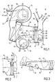
- Figure 1 represents a cabin heating and / or air conditioning system H of a motor vehicle, comprising a housing 10 housing an evaporator 12 and a heating radiator 14, respectively on the inlet side and the outlet side of the housing. Entrance of the housing is connected to a first blower 16 of the radial type having a casing 18 in the form of a scroll in which can turn a propeller 20 around an axis 22.
- the blower 16 is connected to a power supply unit 24 provided two inputs 26 and 28 controlled by a flap 30 of the type flag mounted pivoting around an axis 32. Inputs 26 and 28 are suitable for being fed by a stream respectively outside air AE taken from outside the passenger compartment H, while the air inlet 28 is suitable for being supplied by an AR recirculated air flow taken from inside the passenger compartment.
- the blower 16 can send either an external air flow AE, i.e. a recirculated air flow AR through the evaporator 12.
- the latter is connected to a conventional circuit of air conditioning (not shown).
- the device also comprises a second pulser 32, also of radial type, supplied here by an air flow recirculated AR.
- the blower includes a shaped envelope 34 scroll in which a propeller 36 rotates around an axis 38 parallel to the axis 22.
- the casing 34 has an outlet 40 which opens into the housing 10, opposite the radiator 14.
- the outlet 40 is controlled by an adjustment flap 42 of the flag type, mounted to pivot around an axis 44 and suitable for move between a closed position (shown in broken line) in which the outlet 40 is closed and a open position (shown in solid lines) in which exit 40 is open.
- the first blower 16 is capable of producing an air flow F1 which passes successively through the evaporator 12 and a part upper or upper part 14A of the radiator, while the second blower 32 is capable of producing a second flow of air F2 which passes through a lower part or a lower part 14B of the radiator 14.
- the first air flow F1 can be successively cooled and warmed, while the second air flow F2 can only be reheated.
- the radiator 14 is suitable for being traversed by a fluid hot, usually the engine coolant of the vehicle.
- An adjustment valve 46 makes it possible to adjust, gradually, the flow of hot fluid passing through the radiator and therefore the air flow temperature F1 or F2 at the outlet of the radiator.
- the output 52 is suitable for supplying at least one nozzle for defrosting / demisting of the windshield (not shown), while that outlet 54 is suitable for supplying at least one aerator (not shown) provided on the dashboard of the vehicle.
- the outlet 52 is controlled by a pivoting flap 58 of the type flag, while exit 54 is controlled by a flap swivel 60 of the butterfly type.
- blowers 16 and 32 are both arranged on the same side, or upstream side, of the radiator 14 and the different outputs 52, 54 and 56 communicate all with outlet chamber 48, which is located on the side downstream of the radiator. It follows that the air flows F1 and F2 pass through the radiator 14 in the same direction.
- the device further includes an upper air passage 66 provided in the case near the first part 14A of the radiator and communicating with the outlet chamber 48 which is located in downstream of the radiator.
- This upper air passage 66 is controlled by a flap 68 of the butterfly type mounted pivoting around a axis 70.
- a flap 68 When the flap 68 is at least partially open, a fraction of the flow F1 takes passage 66 without crossing the radiator 14, which allows the temperature of the air flow F1 in the outlet chamber 48 by mixing, adjustable proportions, hot air flow and air flow fresh. This temperature adjustment is thus carried out by the technique called "air adjustment".
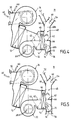
- the device according to the variant of FIG. 3 differs from that of FIG. 1 by the fact that the blower 32 is here a axial blower, so that the flow F2 is sent in parallel to the axis of the propeller and not tangentially as in the case of a radial blower. Pulser 32 does not have therefore no volute type envelope.
- Table 1 below gives, by way of example, different possible distribution modes according to the respective positions of the flaps 42, 62 and 30 and according to the operating mode of the blowers 16 and 32. For the latter, the numbers 0 and 1 correspond respectively to a stop and operating mode.
- the device shown in Figure 5 is similar to that Figures 1 and 4.
- the flap 42 can take two positions 0 and 1 as in the case of the figure 1. It cannot take position 2 of full opening as in the case of FIG. 4.
- the shutter 62 is also a flag type shutter similar to that of the Figure 4 and can take two different positions: 0 and 1.
- Table 2 below gives, by way of example, different distribution modes depending on the position of the flaps 42, 62 and 30 and of the blowers 16 and 32.
- the device shown in Figure 6 is similar to that of Figure 1.
- the respective positions of the flaps 42, 62 and 30 are designated by the numbers 0 and 1.
- Table 3 below gives, by way of example, different distribution modes depending on the respective positions of the flaps and the operating modes of the two blowers.
- Table 4 below gives, by way of example, different modes of distribution of the device as a function of the respective positions of the flaps and of the modes of operation of the blowers.
- the device of figure 8 differs somewhat from the devices previous.
- the first blower 16 is arranged on the upstream side of the radiator.
- the second pulser 32 is disposed on the other side, that is to say the downstream side of the radiator.
- Defrost outputs 52 and aeration 54 both communicate with the outlet chamber 48.
- the feet outlet 56 communicates with a lower part of the housing 10 on the upstream side of the radiator.
- blower 16 is located adjacent to the housing 10 and the second blower 32 can be located adjacent to the housing.
- the second blower can be located remotely the housing (see right part of Figure 8) in particular in the rear PA seating area of the vehicle. In this case, it a connection duct 76 must be provided between the blower 32 and the housing 10.
- blower 32 away from the housing can be interesting to increase the compactness of the device and in addition to take recirculated air from the region of PA rear seats in the passenger compartment.
- the flap 42 can also occupy a third position, or position 2, in which the flow F2 can cross completely the radiator 14.
- the flap 62 can occupy a third position, or position 2, in which the flow F2 which has passed through all the radiator 14, can be directed towards the exit feet 56.
- Distribution modes Defrost Shutter 42 0 Component 62 0 Component 30 0 Pulser 16 1 Pulser 32 0 Defrost + Heating 1 1 0 1 1 Heater 1 (2) 1 (2) 0 or 1 0 1 Heating + ventilation 1 1 0 1 1 Aeration 0 0 0 or 1 1 0
- the device according to FIG. 10 is similar to that of the Figure 8 in the sense that flows F1 and F2 cross the radiator in opposite directions.
- the blower 32 is located upstream of the radiator 14, that is to say near the evaporator 12, not downstream of the radiator 14 near the distribution box 50.
- the blower 32 must be of the suction type and not of the pressure type.
- the flow F2 is taken by an input air 78 which is controlled by the flap 42 and which opens in the passenger compartment H either at the front seats or at rear seat level PA, provided, in the latter case, use a line 80.
- FIG. 11 The variant of Figure 11 is similar to that of Figure 9, in that the flaps 42 and 62 can each occupy three different positions identified by the numbers 0, 1 and 2.
- the device shown in Figure 12 is similar to that in Figure 8. It also has a second outlet feet 82 which is located downstream of the radiator 14, in the lower part of the distribution box 50. This outlet 82 is controlled by a butterfly-type flap 84 mounted pivoting around an axis 86.
- Table 6 below gives, by way of example, different modes of distribution of the device in FIG. 12.
- blowers 16 and 32 are of the radial type and have their scrolls respectively 18 and 34 located on either side of the housing.
- the respective axes 22 and 38 of the propellers are parallel between them.
- the device comprises a flap 42 of the flag type and a flap 62 of the flag type pivotally mounted respectively upstream and downstream of the radiator 14.
- blowers 16 and 32 are also of the radial type and are arranged head to tail with the respective axes 22 and 38 of the propellers, arranged substantially parallel. Pulsers 16 and 32 are arranged on either side of the case, as in the case of Figure 14. However, the axis 22 of the blower 16 is located practically in the plane of evaporator 12, while the axis 38 of the blower 16 is offset from the plane cited above. In fact, the output of the blower 16 opens upstream of the evaporator 12, while the output of the blower 32 opens directly into the housing between the evaporator 12 and the radiator 14.
- the device comprises two flaps 42 of flag type pivotally mounted upstream of the radiator 14 and a flap 62 of the flag type pivotally mounted downstream of the radiator 14.
- the flaps 42 have parallel pivot axes and are ordered in coordination so as to be together in the open position and together in the closed position. In the open position of the flaps 42, the air flows coming respectively from the blowers 16 and 32 are channeled and laminates at the entrance to radiator 14.
- the output of the blower 32 also opens out between the evaporator 12 and the radiator 14, but in a different configuration.
- the device also includes two flag-type flaps 42, but these have pivot axes arranged perpendicularly between them.
- blowers 16 and 32 are also of the radial type and have their envelopes respectively 18 and 34 arranged adjacent to the axes respective 22 and 38 of the propellers which extend parallel between them.
- the scrolls open directly into the housing 10 upstream of the evaporator 12.
- blowers 16 and 32 are also of the radial type.
- the volute 18 of the blower 16 is located near box 10 and communicates directly to the inlet of the evaporator 12.
- the blower 32 is disposed near of the housing between the evaporator 12 and the radiator 14.
- the volute 34 can be integrated into the housing.
- the axes respective 22 and 38 of the propellers are octagonal.
- the scrolls 18 and 34 are located in the immediate vicinity of the housing and include outlet conduits 84, 86 connected upstream of the housing 10 and suitable for conveying respectively the air flow F1 and the air flow F2.
- the scrolls 18 and 34 are attached to a side wall of the housing 10 and they have respective outlet conduits 88 and 90 suitable for conveying the air flows F1 and F2 respectively.
- the device comprises two flaps 42 placed at the outlet of the blowers and pivotally mounted around respective axes perpendicular to each other.
- the device of FIG. 24 is similar to that of the Figure 2, in that we also find a passage upper air 66 provided in the housing near the first part 14A of the radiator and communicating with the outlet 48.
- This air passage is here controlled by a flap 88 of the flag type mounted pivoting about an axis 90.
- This flap can occupy a hot position "CH” in which the passage upper air 66 is closed and the air flow F1 is forced to cross the radiator 14 to reach the outputs 52 and 54. It can also occupy a cold position "F” in which the air flow F1 directly accesses the outputs 52 and 54 without passing through the radiator.
- This component 88 can occupy also intermediate positions to adjust the temperature of the air flow reaching outlets 52 and 54.
- the device comprises a lower air passage 92 provided in the housing 10, near of the second part 14B of the radiator and near the exit feet 56. This passage 92 also communicates with the room outlet 48 provided downstream of the radiator.
- This air passage is controlled by two flaps, a flap 94 of flag type mounted pivoting around an axis 96 and a flap 98 also of the flag type mounted pivoting around an axis 100.
- the flaps 94 and 98 are located respectively on the upstream side and on the downstream side of the radiator 14 and in particular allow to ensure air mixing in the lower part of the housing.
- the upper air passage 66 is controlled by a flap 102 of the drum type which plays substantially the same functions as the flap 88 of the figure 24.
- the lower air passage 92 is controlled here by a single flap 104 in place of the two flaps 94 and 98 described previously.
- This flap 104 is pivotally mounted around an axis 106.
- the flap 104 is replaced by a flag-type flap 108 mounted pivoting around a axis 110.
- the passage of lower air 92 is controlled by a flap 112 of the type butterfly mounted pivoting about an axis 114.
- the upper air passage 66 is controlled by a shutter of mixing 116 mounted pivoting around an axis 118.
- This component is located at the junction of a cold air transmission branch 120 and an air heating branch 122 in which the radiator 14 is housed.
- This flap allows you to adjust the air temperature reaching outputs 52 and 54 by a air adjustment technique.
- the shutter 116 can occupy a cold position "F” in which the air flow F1 is directed to outputs 52 and 54 without being able to pass through the radiator 14 and a hot position "CH” in which the air flow is forced to pass through the radiator 14 to reach the outputs 52 and 54.
- Part 116 can occupy a multiplicity of intermediate positions to adjust the temperature of the air flow by mixing a hot air flow and a cold air flow according to a technique known per se.
- the housing 10 internally houses a stop 124 used to limit the movement of the flap 112 and that of the flap 116.
- the device of FIG. 29 is similar to that of the Figure 1 except that the radiator 14 is formed by the union of two adjacent and independent radiators 14A and 14B clean to be crossed respectively by flows F1 and F2. These two radiators are supplied with hot fluid under the control of valves 46A and 46B both with progressive adjustment.
- a partition 126 is provided between the radiators 14A and 14B to contribute to the separation of flows F1 and F2.
- the device of FIG. 30 is similar to that of the Figure 1, and it further includes an additional radiator 128 located opposite the second part 14A of the radiator and suitable for also being traversed by the second air flow F2.
- This radiator is advantageously of the electric type. This increases the temperature of the F2 flow and promotes the rise in temperature of the lower cabin area, in the area of the feet of the passengers.
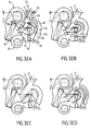
- FIGS. 24 and 28 show different modes of distribution of a device according to the invention resembles those described in FIGS. 24 and 28.
- the device notably includes an air passage upper 66 in which is placed a mixing flap 116 and a lower air passage 92 in which are placed two flaps 94 and 98.
- the output of the blower 32 is controlled by a shutter 42, while a shutter 62 of the flag type is provided in outlet chamber 48.
- FIG. 31A corresponds to a mode of distribution: "defrosting and ventilation ".
- the blower 16 is operating, while the blower 32 is stopped, its output also being closed by shutter 42.
- Shutters 94 and 98 can be in a variable position, while the flap 95 closes access to the feet outlet 56.
- the shutter 62 is in such a position that the air flow having passed through the radiator 14 is directed to the defrost outlet 52 and the ventilation outlet 54.
- the air flow emitted by the blower 16 passes through the evaporator then is then distributed between the air transmission branch cold 120 and the air heating branch 122 by the shutter mixing.
- the device In the position of FIG. 31B, the device is in the "heating + defrosting and heating + ventilation" distribution mode.
- the blowers 16 and 32 are both in operation.
- the flap 42 is open and flap 62 is in a position intermediate.
- flaps 94 and 98 are in a any position.
- the radiator 14 is crossed by a flux F1 in the upper part and by a flow F2 in the lower part, shutters 42 and 62 helping to partition these two flux.
- the defrost 52 and aeration 54 outputs are supplied by a flow of air at a set temperature.
- the output feet 56 is supplied by a hot air flow or temperature mixed coming from the blower 32 and having passed through the lower part of the radiator.
- the device In the position of FIG. 31C, the device is in a distribution mode called "foot heating".
- the blower 16 is stopped, while the blower 32 is in operation.
- the shutter 42 is in the full position opening ; the flap 62 is in a position such that the air flow having passed through the radiator 14 is directed towards the outlet feet 56.
- flaps 94 and 98 can be adjusted in position to adjust the temperature of the air sent to the feet outlet, by varying the proportion of the air flow passing through the radiator and air flow not passing through the radiator.
- the device of FIGS. 31A to 31C can also function well in a configuration where the mix controls are conjugate only in a configuration where the commands of mix are independent.
- FIGS. 32A to 32D showing a device which is similar to that of FIGS. 31A to 31C.
- This device includes a controlled upper air passage 66 by a mixing flap 116 similar to that of FIG. 28.
- the device does not have an air passage lower 92 as in the case of FIGS. 24, 28, 31A to 31C.
- the mixing flap 116 makes it possible to adjust both the temperature of the air flow sent to the defrost outlet 52 and the ventilation outlet 54 and that of the air flow sent to the feet outlet 56.
- the device comprises a mixing chamber 130 receiving air at a set temperature and supplying on the one hand exits 52 and 54 and, on the other hand, the exit feet 56 by a conduit 132, which can communicate with the outlet 48 by a flap 134 of the butterfly type pivotally mounted around an axis 136.
- the blower 16 In the position of FIG. 32A, the blower 16 is in operation, while the blower 32 is stopped, its outlet being closed by the shutter 42.
- the shutter 134 is in a position in which the conduit 132 is isolated from the outlet chamber 48.
- the mixing chamber 130 is supplied with power by an air flow at an adjusted temperature, depending on the position of the mixing flap. The air flow at temperature adjusted is then distributed between outputs 52, 54 and 56.
- the blowers 16 and 32 are both in operation. Flaps 42 and 134 are in a position such that the air flows from the two blowers are compartmentalized.
- the outputs 52 and 54 are supplied by a temperature controlled air flow from blower 16.
- the output feet 56 is supplied by a flow of air coming from the blower 32 and having passed through the part bottom of radiator 14. In this configuration, the mixed air is sent to the defrost and ventilation outlets, while hot air is sent to the feet outlet. This configuration suitable for combined modes with overheating of the feet area.
- the device In the position of FIG. 32C, the device is in a configuration which corresponds to another "heating" mode feet ".
- the shutter 42 is in the fully open position, as is flap 134 so that all of the air flow from the Pulser 32 crosses the total section of the radiator 14. The hot flow from the radiator is thus sent only to feet outlet 56. This operating mode allows setting in rapid temperature of the cabin foot area.
- the device In the position of FIG. 32D, the device is in a other "foot heating" mode.
- the shutter 42 occupies the same position as in Figure 32C.
- component 134 isolates the conduit 132 from the outlet chamber 48.
- the chamber mixer 130 is supplied on the one hand by an air flow cold from the blower 16 and on the other hand by a flow hot air from the blower 32 and having passed through the radiator 14.
- the mixing chamber thus receives a flow at adjusted temperature which can then be distributed among the outputs 52, 54 and 56. Therefore, this mode allows you to adjust the temperature of the air flow sent to the three outlets mentioned above.
- FIGS. 32A to 32C show different modes of distribution of a device produced according to a variant of the device of FIGS. 32A to 32C.
- the conduit 132 has been deleted.
- the outlet chamber 48 always accommodates a flap 62 as described above.
- the device In the position of FIG. 33A, the device is in a "defrost or aeration" mode.
- the blower 16 is in operation, while the blower 32 is stopped, its outlet being closed by the shutter 42.
- the shutter 62 is in a position such that all of the air flow having passed through the radiator 14 is sent to the defrost outlet 52 and the ventilation outlet 54. Thus, these two outlets receive mixed air, while the outlet feet 56 is not powered.
- the device In the position of FIG. 33B, the device is in a "defrost + ventilation” or "heating + defrost” mode.
- the flap 42 is in an intermediate position, as is the shutter 62 which makes it possible to partition the flows emitted respectively by the blower 16 and the blower 32, both Operating.
- Outlets 52 and 54 receive air mixed powered by the blower 16.
- the foot outlet 56 receives hot air emitted by the blower 32 and having crossed the lower outlet of the radiator 14.
- the device In the position of FIG. 33C, the device is in a "foot heating" mode. Pulser 16 is stopped, while the blower 32 is in operation. The flaps 42 and 62 are in a position such that all the air flow emitted by the blower 32 can pass through radiator 14 and then be directed only towards the exit feet 56. It follows that outlet 56 receives a flow of hot air at temperature maximum.
- the device of FIGS. 33A to 33C constitutes a variant of that of FIGS. 32A to 32C, this variant being simplified insofar as it does not allow adjustment of the temperature of the feet heating.
- the device of the invention is susceptible many variant embodiments, particularly in this which concerns the relative positions of the two blowers by report to the housing. These positions can be chosen in depending on the layout and space constraints of the vehicle for which the device is intended.
- the respective envelopes of the blowers can either be reported on the case either be integrated into it, in being for example molded with him.
- the device of the invention makes it possible to broadcast two separate air flows each having an external origin or inside the vehicle.
- the upper part of the passenger compartment will be supplied by an air flow outside (or possibly recirculated) so as to avoid the fogging up of the vehicle windows.
- the part lower of the passenger compartment will preferably be powered by recirculated air to promote heating in particular.
- the upper and lower parts of the passenger compartment of the vehicle can be powered by two streams of treated air independently in temperature.
- the device allows the use of one or two sources heat.
Landscapes
- Physics & Mathematics (AREA)
- Thermal Sciences (AREA)
- Engineering & Computer Science (AREA)
- Mechanical Engineering (AREA)
- Air-Conditioning For Vehicles (AREA)
Applications Claiming Priority (2)
| Application Number | Priority Date | Filing Date | Title |
|---|---|---|---|
| FR9801000A FR2774035B1 (fr) | 1998-01-29 | 1998-01-29 | Dispositif de chauffage et/ou climatisation de vehicule automobile, avec gestion amelioree de l'echange thermique |
| FR9801000 | 1998-01-29 |
Publications (3)
| Publication Number | Publication Date |
|---|---|
| EP0936090A2 true EP0936090A2 (de) | 1999-08-18 |
| EP0936090A3 EP0936090A3 (de) | 1999-08-25 |
| EP0936090B1 EP0936090B1 (de) | 2004-09-22 |
Family
ID=9522339
Family Applications (1)
| Application Number | Title | Priority Date | Filing Date |
|---|---|---|---|
| EP99400202A Expired - Lifetime EP0936090B1 (de) | 1998-01-29 | 1999-01-28 | Heiz- und/oder Klimatisierungsvorrichtung eines Kraftfahrzeuges mit verbessertem Wärmetausch-Management |
Country Status (5)
| Country | Link |
|---|---|
| US (1) | US6422309B2 (de) |
| EP (1) | EP0936090B1 (de) |
| DE (1) | DE69920298T2 (de) |
| ES (1) | ES2229638T3 (de) |
| FR (1) | FR2774035B1 (de) |
Cited By (6)
| Publication number | Priority date | Publication date | Assignee | Title |
|---|---|---|---|---|
| FR2797811A1 (fr) * | 1999-08-31 | 2001-03-02 | Valeo Climatisation | Dispositif de chauffage et/ou climatisation de vehicule automobile avec radiateur de chauffage electrique additionnel |
| FR2805217A1 (fr) * | 2000-02-22 | 2001-08-24 | Valeo Climatisation | Dispositif de conditionnement d'air pour vehicule |
| FR2813560A1 (fr) * | 2000-08-01 | 2002-03-08 | Behr Gmbh & Co | Installation de chauffage et de climatisation pour un vehicule a moteur |
| EP1219477A3 (de) * | 2000-12-28 | 2003-03-05 | Calsonic Kansei Corporation | Fahrzeug-Klimaanlage |
| US6739388B2 (en) * | 2001-07-25 | 2004-05-25 | Mitsubishi Heavy Industries, Ltd. | Air-conditioning system for a vehicle |
| CN104995047A (zh) * | 2013-03-29 | 2015-10-21 | 本田技研工业株式会社 | 车辆用空调装置 |
Families Citing this family (58)
| Publication number | Priority date | Publication date | Assignee | Title |
|---|---|---|---|---|
| FR2814986B1 (fr) * | 2000-10-11 | 2003-02-07 | Valeo Climatisation | Installation de climatisation de vehicule a deux zones de mixage |
| JP3600164B2 (ja) * | 2001-02-13 | 2004-12-08 | 三洋電機株式会社 | 冷暖房用車載空気調和機 |
| US7116479B1 (en) | 2001-07-19 | 2006-10-03 | Wavesplitter Technologies, Inc. | Array polarization beamsplitter and combiner |
| JP4193716B2 (ja) * | 2003-12-15 | 2008-12-10 | 株式会社デンソー | 車両用空調装置 |
| ITTO20031008A1 (it) * | 2003-12-16 | 2005-06-17 | Fiat Ricerche | Sistema di distribuzione di aria per una plancia di autoveicolo e plancia di autoveicolo comprendente tale sistema. |
| US7267086B2 (en) * | 2005-02-23 | 2007-09-11 | Emp Advanced Development, Llc | Thermal management system and method for a heat producing system |
| US7454896B2 (en) * | 2005-02-23 | 2008-11-25 | Emp Advanced Development, Llc | Thermal management system for a vehicle |
| US7228689B2 (en) * | 2005-05-20 | 2007-06-12 | Delphi Technologies, Inc. | Thermo-electric and HVAC seat cooling and heating mode door integration |
| JP2007176391A (ja) * | 2005-12-28 | 2007-07-12 | Calsonic Kansei Corp | 空調装置 |
| US20080016892A1 (en) * | 2006-07-21 | 2008-01-24 | Kilsang Jang | Air conditioner for vehicles |
| DE102008035403A1 (de) * | 2008-07-29 | 2010-02-04 | Behr Industry Gmbh & Co. Kg | Klimaanlage mit Gebläse in einer Land- oder Baumaschine |
| DE102008038933A1 (de) * | 2008-08-13 | 2010-02-18 | Behr Gmbh & Co. Kg | Verfahren zum Steuern einer Heiz- und Lüftungseinheit für ein Fahrzeug mit minimalem Energieverbrauch |
| US8187063B2 (en) * | 2009-03-31 | 2012-05-29 | Honda Motor Co., Ltd. | Evaporator frost prevention control logic for front and rear integrated HVAC system |
| US8997837B2 (en) * | 2009-04-28 | 2015-04-07 | Honda Motor Co., Ltd. | Seal and drain structure for a front and rear integrated HVAC system |
| US8662157B2 (en) * | 2009-07-10 | 2014-03-04 | Keihin Corporation | Vehicular air conditioning apparatus |
| US20110005715A1 (en) * | 2009-07-10 | 2011-01-13 | Keihin Corporation | Vehicular air conditioning apparatus |
| US8267155B2 (en) * | 2009-07-10 | 2012-09-18 | Keihin Corporation | Vehicular air conditioning apparatus |
| US8267165B2 (en) * | 2009-07-10 | 2012-09-18 | Keihin Corporation | Vehicular air conditioning apparatus |
| US8689860B2 (en) * | 2009-07-10 | 2014-04-08 | Keihin Corporation | Vehicular air conditioning apparatus |
| US8403029B2 (en) * | 2009-07-10 | 2013-03-26 | Keihin Corporation | Vehicular air conditioning apparatus |
| US8544528B2 (en) * | 2009-07-10 | 2013-10-01 | Keihin Corporation | Heat exchanger equipped with partitioning members for use in a vehicular air conditioning apparatus |
| US8997838B2 (en) * | 2009-07-10 | 2015-04-07 | Keihin Corporation | Vehicular air conditioning apparatus |
| US20110005730A1 (en) * | 2009-07-10 | 2011-01-13 | Keihin Corporation | Vehicular air conditioning apparatus |
| US20110005707A1 (en) * | 2009-07-10 | 2011-01-13 | Keihin Corporation | Heat exchanger equipped with a partitioning member for use in a vehicular air conditioning apparatus |
| US20110005734A1 (en) * | 2009-07-10 | 2011-01-13 | Keihin Corporation | Vehicular air conditioning apparatus |
| US8662158B2 (en) * | 2009-07-10 | 2014-03-04 | Keihin Corporation | Vehicular air conditioning apparatus |
| US20110005714A1 (en) * | 2009-07-10 | 2011-01-13 | Keihin Corporation | Vehicular air conditioning apparatus |
| US9174511B2 (en) * | 2009-07-10 | 2015-11-03 | Keihin Corporation | Vehicular air conditioning apparatus |
| JP5577661B2 (ja) * | 2009-09-28 | 2014-08-27 | カルソニックカンセイ株式会社 | 車両用空調装置 |
| US20110073281A1 (en) * | 2009-09-29 | 2011-03-31 | Keihin Corporation | Heat exchanger for vehicular air conditioning apparatus |
| US8397795B2 (en) * | 2009-10-15 | 2013-03-19 | Keihin Corporation | Heat exchanger for vehicular air conditioning apparatus |
| US8443873B2 (en) * | 2009-12-02 | 2013-05-21 | Keihin Corporation | Heat exchanger for vehicular air conditioning apparatus |
| DE102010029785A1 (de) * | 2010-06-08 | 2011-12-08 | Behr Gmbh & Co. Kg | Anordnung zum Führen und/oder Mischen zweier Luftströme |
| FR2966390B1 (fr) * | 2010-10-20 | 2013-09-27 | Valeo Systemes Thermiques | Installation de ventilation et de chauffage pour vehicule a propulsion electrique |
| FR2966388B1 (fr) * | 2010-10-20 | 2013-04-26 | Valeo Systemes Thermiques | Installation de ventilation et de chauffage a reserve integree |
| US9840126B2 (en) | 2011-02-18 | 2017-12-12 | Honda Motor Co., Ltd. | Method and apparatus for operating a vehicle HVAC system to prevent output of inverse airflow |
| JP5625993B2 (ja) * | 2011-02-22 | 2014-11-19 | 株式会社デンソー | 車両用空調装置 |
| JP5333496B2 (ja) * | 2011-03-25 | 2013-11-06 | 株式会社デンソー | 車両用空調装置 |
| US9308799B2 (en) * | 2011-03-29 | 2016-04-12 | Denso International America, Inc. | Variable evaporator outlet air pressure distribution |
| US9533543B2 (en) * | 2011-03-29 | 2017-01-03 | Denso International America, Inc. | Multi-blower HVAC layout for improved evaporator performance |
| US20120252341A1 (en) * | 2011-03-29 | 2012-10-04 | Denso International America, Inc. | Hvac control for multi-blower unit |
| US20120252340A1 (en) * | 2011-03-30 | 2012-10-04 | Denso International America, Inc. | Air conditioning apparatus |
| US9636969B2 (en) * | 2011-03-31 | 2017-05-02 | Denso International America, Inc. | Air conditioning apparatus |
| US9227482B2 (en) * | 2011-03-31 | 2016-01-05 | Denso International America, Inc. | Airflow selecting mechanism for a vehicle cabin air conditioning apparatus |
| US9134196B2 (en) * | 2012-08-29 | 2015-09-15 | The Boeing Company | Inlet icing protection simulation system |
| DE102012108891B4 (de) | 2012-09-20 | 2022-01-27 | Hanon Systems | Klimatisierungssystem eines Kraftfahrzeuges und Luftleitvorrichtung für einen Wärmeübertrager |
| DE102013106209B4 (de) * | 2012-09-20 | 2020-09-10 | Hanon Systems | Klimatisierungsvorrichtung eines Kraftfahrzeuges mit einer Wärmeübertrageranordnung zur Wärmeaufnahme |
| US9168810B2 (en) * | 2012-10-09 | 2015-10-27 | Delphi Technologies, Inc. | Heating and cooling system for occupants of the rear portion of a vehicle |
| FR3012080B1 (fr) * | 2013-10-21 | 2018-07-13 | Valeo Systemes Thermiques | Installation de chauffage, ventilation et/ou climatisation pour un habitacle de vehicule automobile |
| EP3623185B1 (de) * | 2014-09-01 | 2023-06-07 | Hanon Systems | Wärmepumpensystem für ein fahrzeug |
| FR3026351B1 (fr) * | 2014-09-25 | 2018-03-23 | Valeo Systemes Thermiques | Dispositif de generation d'un flux d'air |
| FR3026352B1 (fr) * | 2014-09-25 | 2017-11-24 | Valeo Systemes Thermiques | Dispositif de generation d'un flux d'air |
| DE102016203733B4 (de) * | 2015-03-09 | 2025-11-06 | Hanon Systems | Klimaanlagensystem für Motorfahrzeuge |
| JP6592466B2 (ja) * | 2016-01-18 | 2019-10-16 | ハンオン システムズ | 車両用空調システム |
| FR3053006A1 (fr) * | 2016-06-27 | 2017-12-29 | Valeo Systemes Thermiques | Boitier de climatisation pour habitacle de vehicule automobile |
| US20190184787A1 (en) * | 2017-12-20 | 2019-06-20 | Ford Global Technologies, Llc | Panel and defrost plenum |
| FR3115734B1 (fr) * | 2020-11-04 | 2022-10-14 | Valeo Systemes Thermiques | Module de refroidissement pour véhicule automobile électrique ou hybride à turbomachine tangentielle |
| CN113715579A (zh) * | 2021-09-27 | 2021-11-30 | 一汽奔腾轿车有限公司 | 一种汽车速热出风口系统 |
Family Cites Families (28)
| Publication number | Priority date | Publication date | Assignee | Title |
|---|---|---|---|---|
| DE864666C (de) * | 1948-10-02 | 1953-01-26 | Friedrich Dipl-Ing D Nallinger | Heizvorrichtung fuer Kraftfahrzeuge |
| GB884918A (en) * | 1960-06-30 | 1961-12-20 | Smith & Sons Ltd S | Improvements in or relating to combined heating and cooling apparatus for vehicles |
| DE1245774B (de) * | 1960-10-29 | 1967-07-27 | Daimler Benz Ag | Klimaanlage fuer Fahrzeuge, insbesondere fuer Kraftfahrzeuge |
| FR2400161A1 (fr) * | 1977-08-11 | 1979-03-09 | Ferodo Sa | Installation de climatisation d'une enceinte telle que l'habitacle d'un vehicule automobile |
| JPS589774Y2 (ja) * | 1979-05-31 | 1983-02-22 | 日産自動車株式会社 | 自動車用暖房装置 |
| US4412425A (en) * | 1980-12-09 | 1983-11-01 | Nippon Soken, Inc. | Air conditioning and ventilation system |
| JPS57130815A (en) * | 1981-02-04 | 1982-08-13 | Nippon Denso Co Ltd | Air conditioner for automobiles |
| DE3237275C1 (de) * | 1982-10-08 | 1984-04-19 | Daimler-Benz Ag, 7000 Stuttgart | Vorrichtung zum Heizen,Lueften und Kuehlen eines Passagier- und/oder Nutzraumes von Fahrzeugen |
| JPS601018A (ja) * | 1983-06-20 | 1985-01-07 | Mitsubishi Electric Corp | 自動車用空気調和装置 |
| SU1530495A1 (ru) * | 1987-06-26 | 1989-12-23 | Азово-Черноморский Институт Механизации Сельского Хозяйства | Устройство дл вентил ции и отоплени кабины транспортного средства |
| DE3740132A1 (de) * | 1987-11-26 | 1989-06-08 | Daimler Benz Ag | Belueftungseinrichtung fuer den innenraum eines fahrzeuges |
| US4842047A (en) * | 1988-06-03 | 1989-06-27 | Diesel Kiki Co., Ltd. | Air conditioner for automobiles |
| JPH0234420A (ja) * | 1988-07-23 | 1990-02-05 | Sanden Corp | 温水流量調整式自動温度制御装置 |
| JPH0292714A (ja) * | 1988-09-28 | 1990-04-03 | Diesel Kiki Co Ltd | 車両用空調装置 |
| FR2661644B1 (fr) * | 1990-05-04 | 1992-07-17 | Valeo | Installation de chauffage et/ou de climatisation a deux pulseurs d'air pour vehicule automobile. |
| US5199485A (en) * | 1990-08-03 | 1993-04-06 | Hitachi, Ltd. | Air conditioner for motor vehicle having right, left and center temperature controlled vents |
| DE4034290C2 (de) * | 1990-09-04 | 1999-05-20 | Bayerische Motoren Werke Ag | Fahrzeug-Klimagerät |
| US5309731A (en) * | 1991-12-27 | 1994-05-10 | Nippondenso Co., Ltd. | Air conditioning apparatus |
| FR2686837B1 (fr) * | 1992-01-31 | 1995-05-24 | Valeo Thermique Habitacle | Dispositif de chauffage-ventilation de l'habitacle d'un vehicule automobile a moteur a faibles rejets thermiques. |
| JP3161055B2 (ja) * | 1992-07-15 | 2001-04-25 | 株式会社デンソー | 車両用空調装置 |
| DE4327866C1 (de) * | 1993-08-19 | 1994-09-22 | Daimler Benz Ag | Einrichtung zur Klimatisierung des Fahrgastraums und zur Kühlung des Antriebssystems von Elektrofahrzeugen |
| JP3222375B2 (ja) | 1995-03-20 | 2001-10-29 | トヨタ自動車株式会社 | 車両用空気調和装置 |
| DE19651279B4 (de) * | 1995-12-13 | 2004-09-16 | Denso Corp., Kariya | Klimaanlage für ein Fahrzeug |
| DE19613344B4 (de) * | 1996-04-03 | 2005-04-14 | Behr Gmbh & Co. Kg | Heizungs- oder Klimaanlage für ein Kraftfahrzeug |
| JP3758286B2 (ja) * | 1996-06-26 | 2006-03-22 | 株式会社デンソー | 送風ユニット |
| JPH10119533A (ja) * | 1996-10-22 | 1998-05-12 | Denso Corp | 車両用空調装置 |
| JP3750255B2 (ja) * | 1997-01-07 | 2006-03-01 | 株式会社デンソー | 車両用空調装置 |
| US6092592A (en) * | 1998-05-28 | 2000-07-25 | Denso Corporation | Air conditioner for vehicle |
-
1998
- 1998-01-29 FR FR9801000A patent/FR2774035B1/fr not_active Expired - Fee Related
-
1999
- 1999-01-28 EP EP99400202A patent/EP0936090B1/de not_active Expired - Lifetime
- 1999-01-28 DE DE69920298T patent/DE69920298T2/de not_active Expired - Fee Related
- 1999-01-28 ES ES99400202T patent/ES2229638T3/es not_active Expired - Lifetime
- 1999-01-29 US US09/240,382 patent/US6422309B2/en not_active Expired - Fee Related
Cited By (11)
| Publication number | Priority date | Publication date | Assignee | Title |
|---|---|---|---|---|
| FR2797811A1 (fr) * | 1999-08-31 | 2001-03-02 | Valeo Climatisation | Dispositif de chauffage et/ou climatisation de vehicule automobile avec radiateur de chauffage electrique additionnel |
| FR2805217A1 (fr) * | 2000-02-22 | 2001-08-24 | Valeo Climatisation | Dispositif de conditionnement d'air pour vehicule |
| WO2001062530A1 (fr) * | 2000-02-22 | 2001-08-30 | Valeo Climatisation | Dispositif de conditionnement d'air pour vehicule |
| JP2003523874A (ja) * | 2000-02-22 | 2003-08-12 | ヴァレオ クリマチザション | 自動車用空調装置 |
| US6668909B2 (en) | 2000-02-22 | 2003-12-30 | Valeo Climatisation | Air-conditioning device for motor vehicle |
| FR2813560A1 (fr) * | 2000-08-01 | 2002-03-08 | Behr Gmbh & Co | Installation de chauffage et de climatisation pour un vehicule a moteur |
| US7156166B2 (en) | 2000-08-01 | 2007-01-02 | Behr Gmbh & Co. | Heating and air-conditioning system for a motor vehicle |
| EP1219477A3 (de) * | 2000-12-28 | 2003-03-05 | Calsonic Kansei Corporation | Fahrzeug-Klimaanlage |
| US6739388B2 (en) * | 2001-07-25 | 2004-05-25 | Mitsubishi Heavy Industries, Ltd. | Air-conditioning system for a vehicle |
| CN104995047A (zh) * | 2013-03-29 | 2015-10-21 | 本田技研工业株式会社 | 车辆用空调装置 |
| CN104995047B (zh) * | 2013-03-29 | 2018-06-15 | 本田技研工业株式会社 | 车辆用空调装置 |
Also Published As
| Publication number | Publication date |
|---|---|
| FR2774035A1 (fr) | 1999-07-30 |
| EP0936090A3 (de) | 1999-08-25 |
| US6422309B2 (en) | 2002-07-23 |
| EP0936090B1 (de) | 2004-09-22 |
| FR2774035B1 (fr) | 2000-03-31 |
| US20020017383A1 (en) | 2002-02-14 |
| DE69920298T2 (de) | 2005-11-17 |
| DE69920298D1 (de) | 2004-10-28 |
| ES2229638T3 (es) | 2005-04-16 |
Similar Documents
| Publication | Publication Date | Title |
|---|---|---|
| EP0936090B1 (de) | Heiz- und/oder Klimatisierungsvorrichtung eines Kraftfahrzeuges mit verbessertem Wärmetausch-Management | |
| FR2703304A1 (fr) | Boîtier de distribution pour une installation de chauffage-ventilation de l'habitacle d'un véhicule automobile. | |
| EP1514707A1 (de) | Verbesserte Lufttemperatursteuerung einer Heiz- und/oder Klimaanlage einer Fahrgastzelle | |
| EP0748708B1 (de) | Vorrichtung zur Heizung und /oder Klimatisierung eines Fahrzeuginnenraumes | |
| FR2742383A1 (fr) | Dispositif de chauffage et/ou climatisation de l'habitacle d'un vehicule automobile | |
| FR2789629A1 (fr) | Installation de chauffage et/ou climatisation a mixage d'air pour vehicule automobile | |
| EP0780251B1 (de) | Vorrichtung für die Heizung, Lüftung und/oder Klimatisierung, insbesondere für Kraftwagen | |
| EP0246948B2 (de) | Heiz- und Belüftungseinrichtung für ein Kraftfahrzeug | |
| EP0591066B1 (de) | Vorrichtung für die Heizung und Lüftung des Innenraums von einem Fahrzeug | |
| FR2795684A1 (fr) | Dispositif perfectionne de chauffage, ventilation et/ou climatisation d'un habitacle, notamment de vehicule automobile, a reglage de temperature par zones | |
| FR2929558A1 (fr) | Organe de mixage d'air du type volet-tambour et installation de chauffage, de ventilation et/ou de climatisation equipee d'un tel organe de mixage d'air. | |
| EP0961698B1 (de) | Heizungs- und/oder klimaanlage, integriert in einem fahrzeugarmaturenbrett | |
| EP1514708B1 (de) | Heiz und/oder Klimatiserungsvorrichtung für Fahrzeuginnenraum, mit hoch entwickelter aerothermischer Regelung | |
| EP1090785B1 (de) | Verbessertes Luftbehandlungsgehäuse eines Innenraums insbesondere eines Kraftfahrzeugs | |
| FR2795683A1 (fr) | Dispositif de chauffage et/ou climatisation d'un habitacle, notamment de vehicule automobile, a conduit transversal | |
| FR2737156A1 (fr) | Dispositif de chauffage-ventilation de l'habitacle d'un vehicule automobile | |
| FR2720695A1 (fr) | Dispositif de chauffage et/ou de climatisation de l'habitacle d'un véhicule. | |
| EP0749857B1 (de) | Vorrichtung zur Heizung, Lüftung eines Fahrzeuginnenraumes | |
| FR2703305A1 (fr) | Boîtier de chauffage pour une installation de chauffage-ventilation de l'habitacle d'un véhicule automobile. | |
| EP1510379B1 (de) | Luftverteilungsmodul für eine Heiz-Lüftungs- oder Klimaanlage eines Fahrgastraumes | |
| EP1405743B1 (de) | Vorrichtung zur Heizung und/oder Klimatisierung eines Fahrzeuginnenraumes mit reduziertem Druckverlust | |
| FR2783465A1 (fr) | Dispositif de chauffage-climatisation integre dans une planche de bord de vehicule automobile | |
| FR2728511A1 (fr) | Dispositif de chauffage et/ou de climatisation, notamment pour vehicule automobile | |
| FR2720694A1 (fr) | Dispositif de chauffage-climatisation de l'habitacle d'un véhicule. | |
| EP0781673B1 (de) | Heiz-oder Klimaanlage des Fahrzeuginnenraums eines Kraftfahrzeuges |
Legal Events
| Date | Code | Title | Description |
|---|---|---|---|
| PUAI | Public reference made under article 153(3) epc to a published international application that has entered the european phase |
Free format text: ORIGINAL CODE: 0009012 |
|
| PUAL | Search report despatched |
Free format text: ORIGINAL CODE: 0009013 |
|
| AK | Designated contracting states |
Kind code of ref document: A2 Designated state(s): DE ES GB IT |
|
| AX | Request for extension of the european patent |
Free format text: AL;LT;LV;MK;RO;SI |
|
| AK | Designated contracting states |
Kind code of ref document: A3 Designated state(s): AT BE CH CY DE DK ES FI FR GB GR IE IT LI LU MC NL PT SE |
|
| AX | Request for extension of the european patent |
Free format text: AL;LT;LV;MK;RO;SI |
|
| 17P | Request for examination filed |
Effective date: 20000121 |
|
| AKX | Designation fees paid |
Free format text: DE ES GB IT |
|
| 17Q | First examination report despatched |
Effective date: 20020813 |
|
| GRAP | Despatch of communication of intention to grant a patent |
Free format text: ORIGINAL CODE: EPIDOSNIGR1 |
|
| GRAS | Grant fee paid |
Free format text: ORIGINAL CODE: EPIDOSNIGR3 |
|
| GRAA | (expected) grant |
Free format text: ORIGINAL CODE: 0009210 |
|
| AK | Designated contracting states |
Kind code of ref document: B1 Designated state(s): DE ES GB IT |
|
| REG | Reference to a national code |
Ref country code: GB Ref legal event code: FG4D Free format text: NOT ENGLISH |
|
| GBT | Gb: translation of ep patent filed (gb section 77(6)(a)/1977) |
Effective date: 20040922 |
|
| REF | Corresponds to: |
Ref document number: 69920298 Country of ref document: DE Date of ref document: 20041028 Kind code of ref document: P |
|
| REG | Reference to a national code |
Ref country code: ES Ref legal event code: FG2A Ref document number: 2229638 Country of ref document: ES Kind code of ref document: T3 |
|
| PLBE | No opposition filed within time limit |
Free format text: ORIGINAL CODE: 0009261 |
|
| STAA | Information on the status of an ep patent application or granted ep patent |
Free format text: STATUS: NO OPPOSITION FILED WITHIN TIME LIMIT |
|
| 26N | No opposition filed |
Effective date: 20050623 |
|
| PGFP | Annual fee paid to national office [announced via postgrant information from national office to epo] |
Ref country code: ES Payment date: 20080125 Year of fee payment: 10 |
|
| PGFP | Annual fee paid to national office [announced via postgrant information from national office to epo] |
Ref country code: IT Payment date: 20080123 Year of fee payment: 10 Ref country code: GB Payment date: 20080111 Year of fee payment: 10 Ref country code: DE Payment date: 20080110 Year of fee payment: 10 |
|
| GBPC | Gb: european patent ceased through non-payment of renewal fee |
Effective date: 20090128 |
|
| PG25 | Lapsed in a contracting state [announced via postgrant information from national office to epo] |
Ref country code: DE Free format text: LAPSE BECAUSE OF NON-PAYMENT OF DUE FEES Effective date: 20090801 |
|
| PG25 | Lapsed in a contracting state [announced via postgrant information from national office to epo] |
Ref country code: GB Free format text: LAPSE BECAUSE OF NON-PAYMENT OF DUE FEES Effective date: 20090128 |
|
| REG | Reference to a national code |
Ref country code: ES Ref legal event code: FD2A Effective date: 20090129 |
|
| PG25 | Lapsed in a contracting state [announced via postgrant information from national office to epo] |
Ref country code: ES Free format text: LAPSE BECAUSE OF NON-PAYMENT OF DUE FEES Effective date: 20090129 |
|
| PG25 | Lapsed in a contracting state [announced via postgrant information from national office to epo] |
Ref country code: IT Free format text: LAPSE BECAUSE OF NON-PAYMENT OF DUE FEES Effective date: 20090128 |