EP0936100B1 - Dachstromabnehmer für Schienenfahrzeuge mit Neigetechnik - Google Patents
Dachstromabnehmer für Schienenfahrzeuge mit Neigetechnik Download PDFInfo
- Publication number
- EP0936100B1 EP0936100B1 EP99103267A EP99103267A EP0936100B1 EP 0936100 B1 EP0936100 B1 EP 0936100B1 EP 99103267 A EP99103267 A EP 99103267A EP 99103267 A EP99103267 A EP 99103267A EP 0936100 B1 EP0936100 B1 EP 0936100B1
- Authority
- EP
- European Patent Office
- Prior art keywords
- pantograph
- pendulums
- frame
- roof
- pendulum
- Prior art date
- Legal status (The legal status is an assumption and is not a legal conclusion. Google has not performed a legal analysis and makes no representation as to the accuracy of the status listed.)
- Expired - Lifetime
Links
- 238000005516 engineering process Methods 0.000 title claims description 5
- 239000012212 insulator Substances 0.000 claims description 5
- 239000012811 non-conductive material Substances 0.000 claims description 2
- 230000003137 locomotive effect Effects 0.000 abstract 1
- 238000005452 bending Methods 0.000 description 5
- 238000010276 construction Methods 0.000 description 5
- 230000002349 favourable effect Effects 0.000 description 2
- 230000005484 gravity Effects 0.000 description 2
- 230000000712 assembly Effects 0.000 description 1
- 238000000429 assembly Methods 0.000 description 1
- 230000003993 interaction Effects 0.000 description 1
- 125000006850 spacer group Chemical group 0.000 description 1
- 230000001360 synchronised effect Effects 0.000 description 1
- 230000007704 transition Effects 0.000 description 1
Images

Classifications
-
- B—PERFORMING OPERATIONS; TRANSPORTING
- B60—VEHICLES IN GENERAL
- B60L—PROPULSION OF ELECTRICALLY-PROPELLED VEHICLES; SUPPLYING ELECTRIC POWER FOR AUXILIARY EQUIPMENT OF ELECTRICALLY-PROPELLED VEHICLES; ELECTRODYNAMIC BRAKE SYSTEMS FOR VEHICLES IN GENERAL; MAGNETIC SUSPENSION OR LEVITATION FOR VEHICLES; MONITORING OPERATING VARIABLES OF ELECTRICALLY-PROPELLED VEHICLES; ELECTRIC SAFETY DEVICES FOR ELECTRICALLY-PROPELLED VEHICLES
- B60L5/00—Current collectors for power supply lines of electrically-propelled vehicles
- B60L5/18—Current collectors for power supply lines of electrically-propelled vehicles using bow-type collectors in contact with trolley wire
- B60L5/19—Current collectors for power supply lines of electrically-propelled vehicles using bow-type collectors in contact with trolley wire using arrangements for effecting collector movement transverse to the direction of vehicle motion
-
- B—PERFORMING OPERATIONS; TRANSPORTING
- B60—VEHICLES IN GENERAL
- B60L—PROPULSION OF ELECTRICALLY-PROPELLED VEHICLES; SUPPLYING ELECTRIC POWER FOR AUXILIARY EQUIPMENT OF ELECTRICALLY-PROPELLED VEHICLES; ELECTRODYNAMIC BRAKE SYSTEMS FOR VEHICLES IN GENERAL; MAGNETIC SUSPENSION OR LEVITATION FOR VEHICLES; MONITORING OPERATING VARIABLES OF ELECTRICALLY-PROPELLED VEHICLES; ELECTRIC SAFETY DEVICES FOR ELECTRICALLY-PROPELLED VEHICLES
- B60L2200/00—Type of vehicles
- B60L2200/26—Rail vehicles
Definitions
- the invention relates to a pantograph for rail vehicles with tilting technology according to the preamble of claim 1.
- a pantograph is described, which is arranged on the car roof in arcuate roller guides in the lateral direction relative to the roof movable, wherein the pantograph is pivotally connected to a fixed to the bogie column which holds the pantograph in a particular position relative to the bogie.
- the arrangement of the complex mechanical connection between the bogie and Dachstromabêt device, which brings a constriction of the spatial inner profile and is massively designed, proves to be disadvantageous in this construction.
- Also known (Railway Gazette International, May 1980, Sheet XI) is a pantograph device which is also equipped with a linkage from the drive to the pantograph which utilizes a rocker arm system to counteract the pantograph for body tilt.
- the invention is based on the problem to design a pantograph for rail vehicles with tilting technology, the transverse system is moved by a pendulum guide and claimed at high lateral and longitudinal stability no space in the roof area of the rail vehicle.
- the problem is solved in a generic Dachstromabêt for rail vehicles with tilting technology according to the preamble of claim 1 by the features stated in the characterizing part of claim 1.
- pantograph is inserted into a compact lightweight construction, which is particularly stable in the direction of travel and slightly oscillating formed transversely to the direction of travel, with the moving part of the lightweight construction itself, to a twisting about his vertical standing axis (lurching) to prevent largely, is equipped with a high lateral stability.
- This structurally stable design which is also suitable for use on vehicles at high speeds, regardless of the Wagenkastenfederung a simple, straightforward and flawless functioning structure, from the low masses result in low inertia, the inner profile of the rail vehicle, especially in Roof area, not restricted.
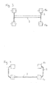
- the pantograph 7 is arranged transversely to the longitudinal axis of the vehicle on its roof.
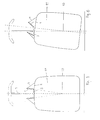
- a non-illustrated roof frame integrated base frame 1 has bearing blocks 4, which rise above the roof contour, and are suspended on the upper pendulum bearing 5 a the pendulum 2, to which in turn by means of lower pendulum bearing 5 b, a frame 3 is articulated transversely to the direction of travel ,
- On this frame insulators 6 are constructed with the pantograph 7. From its shape, the frame 3 is kept flat in its height and flat and arranged above the roof contour. In this construction shown, it can be seen that the lower attachment of the insulators 6 and the lower pendulum bearing 5 b in the interaction of the individual assemblies are located approximately in one plane.
- the base frame 1 with frame 3 represents a complete executed in lightweight construction assembly group. If necessary, can be replaced together with the pantograph 7.
- the front with the rear pendulum 2 In order to be able to transmit both longitudinal forces diagonally and torsional forces between the front and rear pendulums 2 and to prevent the current collector 7 from rotating about its vertical axis when pivoted, are the front with the rear pendulum 2, at least one side, torque-rigid connected.
- successive Pendulum 2 are as in FIG. 3 and FIG. 4 represented connected to each other by means of a stiffening 9 designed as bending and torsion-resistant rod, wherein in Fig.
- the upper pendulum bearing 5 a bearing block 4 hold the upper ends of the pendulum 2 arranged side by side at a distance A to each other, while the lower ends of the pendulum 2 b in the region of the lower pendulum bearing 5 b have a distance A '.
- the distance A is greater than the distance A 'in such a ratio that in the normal position of the car body 11 on the one hand the roof pantograph 7 attacks approximately centrally on the contact wire and on the other the imaginary extensions of the pendulum axes in the Drehpol 10 of the car body 11 intersect.
- the frame 3, the pendulum 2 and / or the bearing blocks 4 may be made of electrically non-conductive material.
- the drive 8 a; 8 b as a rotary drive 8 b in a pendulum bearing 5 a (optionally 5 b) is integrated.
- the control of the position of the frame 3 and thus of the pantograph 7 to the contact wire, as well as the control of the drive for synchronous movement of the Wagenkastenneige Rheinwald, Inc., the car body 11 is automatically pivoted to the normal position, and consequently also the pantograph 7 assumes its normal position.
- the vertical height deviation resulting from the tilting movement can be neglected, since there is sufficient leeway for the pantograph 7 from the lower shut-off position to the contact at the lowest contact wire height.
Landscapes
- Engineering & Computer Science (AREA)
- Power Engineering (AREA)
- Transportation (AREA)
- Mechanical Engineering (AREA)
- Current-Collector Devices For Electrically Propelled Vehicles (AREA)
Applications Claiming Priority (2)
| Application Number | Priority Date | Filing Date | Title |
|---|---|---|---|
| DE19805950A DE19805950C2 (de) | 1998-02-13 | 1998-02-13 | Dachstromabnehmer für Schienenfahrzeuge mit Neigetechnik |
| DE19805950 | 1998-02-13 |
Publications (2)
| Publication Number | Publication Date |
|---|---|
| EP0936100A1 EP0936100A1 (de) | 1999-08-18 |
| EP0936100B1 true EP0936100B1 (de) | 2010-12-15 |
Family
ID=7857641
Family Applications (1)
| Application Number | Title | Priority Date | Filing Date |
|---|---|---|---|
| EP99103267A Expired - Lifetime EP0936100B1 (de) | 1998-02-13 | 1999-02-05 | Dachstromabnehmer für Schienenfahrzeuge mit Neigetechnik |
Country Status (4)
| Country | Link |
|---|---|
| EP (1) | EP0936100B1 (cs) |
| AT (1) | ATE491593T1 (cs) |
| CZ (1) | CZ293081B6 (cs) |
| DE (2) | DE19805950C2 (cs) |
Families Citing this family (1)
| Publication number | Priority date | Publication date | Assignee | Title |
|---|---|---|---|---|
| FR2800680B1 (fr) * | 1999-11-10 | 2003-01-17 | Alstom | Ensemble de captage de courant et vehicule ferroviaire correspondant |
Family Cites Families (5)
| Publication number | Priority date | Publication date | Assignee | Title |
|---|---|---|---|---|
| AT327289B (de) * | 1971-09-08 | 1976-01-26 | Siemens Ag Oesterreich | Schienenfahrzeug mit einem scherenstromabnehmer |
| SE8105354L (sv) * | 1981-09-09 | 1983-03-10 | Asea Ab | Anordning av stromavtagare pa ett sparbundet fordon |
| DE19603077C2 (de) * | 1996-01-19 | 1997-11-20 | Inst Schienenfahrzeuge | Stromabnehmer für Schienenfahrzeuge mit Neigetechnik |
| DE29613541U1 (de) * | 1996-08-05 | 1997-06-05 | Siemens AG, 80333 München | Schienenfahrzeug |
| DE19614554A1 (de) * | 1996-04-12 | 1997-10-16 | Siemens Ag | Schienenfahrzeug |
-
1998
- 1998-02-13 DE DE19805950A patent/DE19805950C2/de not_active Expired - Fee Related
-
1999
- 1999-02-05 DE DE59915226T patent/DE59915226D1/de not_active Expired - Lifetime
- 1999-02-05 EP EP99103267A patent/EP0936100B1/de not_active Expired - Lifetime
- 1999-02-05 AT AT99103267T patent/ATE491593T1/de active
- 1999-02-10 CZ CZ1999444A patent/CZ293081B6/cs not_active IP Right Cessation
Also Published As
| Publication number | Publication date |
|---|---|
| CZ293081B6 (cs) | 2004-02-18 |
| DE19805950A1 (de) | 1999-08-26 |
| ATE491593T1 (de) | 2011-01-15 |
| DE19805950C2 (de) | 2000-05-11 |
| CZ44499A3 (cs) | 1999-09-15 |
| EP0936100A1 (de) | 1999-08-18 |
| DE59915226D1 (de) | 2011-01-27 |
Similar Documents
| Publication | Publication Date | Title |
|---|---|---|
| DE2660079C3 (de) | Verstelleinrichtung für einen Schienenfahrzeug-Radsatz in einem zwei- oder mehrachsigen Drehgestell | |
| DE69404031T2 (de) | Aus mehreren modulen zusammengestelltes und durch eine zusammengesetzte verbindung gekoppeltes fahrzeug | |
| DE3826930C2 (de) | Radaufhängungssystem | |
| DE2839904C2 (de) | Wankstützvorrichtung für ein Schienenfahrzeug mit Drehgestellen | |
| AT405166B (de) | Drehgestell-fahrwerk für ein schienenfahrzeug | |
| DE102021207821A1 (de) | Stromabnehmer für ein elektrisch oder hybridelektrisch angetriebenes Straßenfahrzeug | |
| EP3971013A1 (de) | Stromabnehmer und ein mit einem solchen ausgestattetes, elektrisch oder hybridelektrisch angetriebenes strassenfahrzeug | |
| DE102014201621B4 (de) | Verbundlenkerachse für Fahrzeuge | |
| EP0848676A1 (de) | Drehgestell für schienenfahrzeuge | |
| EP0699149B1 (de) | Wankstütze für schienenfahrzeuge mit einer querneigeeinrichtung | |
| EP0811512A1 (de) | Radaufhängung für ein Kraftfahrzeug | |
| EP0936100B1 (de) | Dachstromabnehmer für Schienenfahrzeuge mit Neigetechnik | |
| EP0785100B1 (de) | Stromabnehmer für Schienenfahrzeuge mit Neigetechnik | |
| DE2417043A1 (de) | Fahrzeugaufhaengung | |
| DE60011014T2 (de) | Vorrichtung mit einem ersten Rahmen und einem zweiten Rahmen, das lateral zum ersten Rahmen pendelt, und ein entsprechendes Schienenfahrzeug | |
| DE4102884A1 (de) | Lenkanordnung fuer raupenfahrwerke von bandschleifenwagen | |
| DE3221755A1 (de) | Drehgestell fuer ein schienenfahrzeug | |
| WO1999042975A1 (de) | Bewegungssystem | |
| EP0485732A2 (de) | Baufahrzeug, vorzugsweise Radlader mit Knickrahmenlenkung | |
| DE3039051A1 (de) | Starrachse, insbesondere angetriebene hinterachse fuer fahrzeuge | |
| DE10058017A1 (de) | Kraftfahrzeugsitz | |
| DE10130636B4 (de) | Vorrichtung zur Querführung eines Achskörpers einer Fahrzeugachse, insbesondere eines Nutzfahrzeugs | |
| DE102010029804B4 (de) | Fahrwerkseinheit | |
| DE3409103C2 (cs) | ||
| EP0679561B1 (de) | Selbstlenkendes, dreiachsiges Laufgestell mit Lenkbalken |
Legal Events
| Date | Code | Title | Description |
|---|---|---|---|
| PUAI | Public reference made under article 153(3) epc to a published international application that has entered the european phase |
Free format text: ORIGINAL CODE: 0009012 |
|
| AK | Designated contracting states |
Kind code of ref document: A1 Designated state(s): AT CH DE ES FI FR GB IT LI PT SE |
|
| AX | Request for extension of the european patent |
Free format text: AL;LT;LV;MK;RO;SI |
|
| 17P | Request for examination filed |
Effective date: 20000201 |
|
| AKX | Designation fees paid |
Free format text: AT CH DE ES FI FR GB IT LI PT SE |
|
| RAP1 | Party data changed (applicant data changed or rights of an application transferred) |
Owner name: BOMBARDIER TRANSPORTATION (BAHNTECHNOLOGIE) HOLDIN |
|
| 17Q | First examination report despatched |
Effective date: 20071128 |
|
| GRAP | Despatch of communication of intention to grant a patent |
Free format text: ORIGINAL CODE: EPIDOSNIGR1 |
|
| GRAC | Information related to communication of intention to grant a patent modified |
Free format text: ORIGINAL CODE: EPIDOSCIGR1 |
|
| GRAS | Grant fee paid |
Free format text: ORIGINAL CODE: EPIDOSNIGR3 |
|
| GRAA | (expected) grant |
Free format text: ORIGINAL CODE: 0009210 |
|
| RAP1 | Party data changed (applicant data changed or rights of an application transferred) |
Owner name: BOMBARDIER TRANSPORTATION (BAHNTECHNOLOGIE) HOLDIN |
|
| AK | Designated contracting states |
Kind code of ref document: B1 Designated state(s): AT CH DE ES FI FR GB IT LI PT SE |
|
| REG | Reference to a national code |
Ref country code: GB Ref legal event code: FG4D Free format text: NOT ENGLISH Ref country code: CH Ref legal event code: EP |
|
| REF | Corresponds to: |
Ref document number: 59915226 Country of ref document: DE Date of ref document: 20110127 Kind code of ref document: P |
|
| REG | Reference to a national code |
Ref country code: CH Ref legal event code: NV Representative=s name: ABREMA AGENCE BREVET ET MARQUES, GANGUILLET |
|
| REG | Reference to a national code |
Ref country code: SE Ref legal event code: TRGR |
|
| PG25 | Lapsed in a contracting state [announced via postgrant information from national office to epo] |
Ref country code: FI Free format text: LAPSE BECAUSE OF FAILURE TO SUBMIT A TRANSLATION OF THE DESCRIPTION OR TO PAY THE FEE WITHIN THE PRESCRIBED TIME-LIMIT Effective date: 20101215 |
|
| PG25 | Lapsed in a contracting state [announced via postgrant information from national office to epo] |
Ref country code: ES Free format text: LAPSE BECAUSE OF FAILURE TO SUBMIT A TRANSLATION OF THE DESCRIPTION OR TO PAY THE FEE WITHIN THE PRESCRIBED TIME-LIMIT Effective date: 20110326 Ref country code: PT Free format text: LAPSE BECAUSE OF FAILURE TO SUBMIT A TRANSLATION OF THE DESCRIPTION OR TO PAY THE FEE WITHIN THE PRESCRIBED TIME-LIMIT Effective date: 20110415 |
|
| PLBE | No opposition filed within time limit |
Free format text: ORIGINAL CODE: 0009261 |
|
| STAA | Information on the status of an ep patent application or granted ep patent |
Free format text: STATUS: NO OPPOSITION FILED WITHIN TIME LIMIT |
|
| 26N | No opposition filed |
Effective date: 20110916 |
|
| GBPC | Gb: european patent ceased through non-payment of renewal fee |
Effective date: 20110315 |
|
| REG | Reference to a national code |
Ref country code: DE Ref legal event code: R097 Ref document number: 59915226 Country of ref document: DE Effective date: 20110916 |
|
| PG25 | Lapsed in a contracting state [announced via postgrant information from national office to epo] |
Ref country code: GB Free format text: LAPSE BECAUSE OF NON-PAYMENT OF DUE FEES Effective date: 20110315 |
|
| PGFP | Annual fee paid to national office [announced via postgrant information from national office to epo] |
Ref country code: CH Payment date: 20120221 Year of fee payment: 14 Ref country code: FR Payment date: 20120227 Year of fee payment: 14 |
|
| PGFP | Annual fee paid to national office [announced via postgrant information from national office to epo] |
Ref country code: DE Payment date: 20120221 Year of fee payment: 14 |
|
| PGFP | Annual fee paid to national office [announced via postgrant information from national office to epo] |
Ref country code: SE Payment date: 20120217 Year of fee payment: 14 Ref country code: IT Payment date: 20120224 Year of fee payment: 14 |
|
| PGFP | Annual fee paid to national office [announced via postgrant information from national office to epo] |
Ref country code: AT Payment date: 20120213 Year of fee payment: 14 |
|
| REG | Reference to a national code |
Ref country code: CH Ref legal event code: PL |
|
| REG | Reference to a national code |
Ref country code: SE Ref legal event code: EUG |
|
| REG | Reference to a national code |
Ref country code: AT Ref legal event code: MM01 Ref document number: 491593 Country of ref document: AT Kind code of ref document: T Effective date: 20130228 |
|
| PG25 | Lapsed in a contracting state [announced via postgrant information from national office to epo] |
Ref country code: CH Free format text: LAPSE BECAUSE OF NON-PAYMENT OF DUE FEES Effective date: 20130228 Ref country code: AT Free format text: LAPSE BECAUSE OF NON-PAYMENT OF DUE FEES Effective date: 20130228 Ref country code: SE Free format text: LAPSE BECAUSE OF NON-PAYMENT OF DUE FEES Effective date: 20130206 Ref country code: LI Free format text: LAPSE BECAUSE OF NON-PAYMENT OF DUE FEES Effective date: 20130228 |
|
| REG | Reference to a national code |
Ref country code: FR Ref legal event code: ST Effective date: 20131031 |
|
| REG | Reference to a national code |
Ref country code: DE Ref legal event code: R119 Ref document number: 59915226 Country of ref document: DE Effective date: 20130903 |
|
| PG25 | Lapsed in a contracting state [announced via postgrant information from national office to epo] |
Ref country code: IT Free format text: LAPSE BECAUSE OF NON-PAYMENT OF DUE FEES Effective date: 20130205 |
|
| PG25 | Lapsed in a contracting state [announced via postgrant information from national office to epo] |
Ref country code: FR Free format text: LAPSE BECAUSE OF NON-PAYMENT OF DUE FEES Effective date: 20130228 Ref country code: DE Free format text: LAPSE BECAUSE OF NON-PAYMENT OF DUE FEES Effective date: 20130903 |