EP0936162A1 - Convoyeur à vibrations avec des entraínements montés latéralement - Google Patents
Convoyeur à vibrations avec des entraínements montés latéralement Download PDFInfo
- Publication number
- EP0936162A1 EP0936162A1 EP99300997A EP99300997A EP0936162A1 EP 0936162 A1 EP0936162 A1 EP 0936162A1 EP 99300997 A EP99300997 A EP 99300997A EP 99300997 A EP99300997 A EP 99300997A EP 0936162 A1 EP0936162 A1 EP 0936162A1
- Authority
- EP
- European Patent Office
- Prior art keywords
- trough
- conveyor assembly
- vibratory conveyor
- actuators
- assembly according
- Prior art date
- Legal status (The legal status is an assumption and is not a legal conclusion. Google has not performed a legal analysis and makes no representation as to the accuracy of the status listed.)
- Granted
Links
- 230000001154 acute effect Effects 0.000 claims description 4
- 230000005484 gravity Effects 0.000 claims description 3
- 239000000463 material Substances 0.000 abstract description 22
- 229910000831 Steel Inorganic materials 0.000 description 4
- 239000010959 steel Substances 0.000 description 4
- 238000010276 construction Methods 0.000 description 3
- 230000001066 destructive effect Effects 0.000 description 2
- 238000006073 displacement reaction Methods 0.000 description 2
- 229910000746 Structural steel Inorganic materials 0.000 description 1
- 239000006096 absorbing agent Substances 0.000 description 1
- 238000013016 damping Methods 0.000 description 1
- 230000000694 effects Effects 0.000 description 1
- 239000011521 glass Substances 0.000 description 1
- 238000005007 materials handling Methods 0.000 description 1
- 238000012986 modification Methods 0.000 description 1
- 230000004048 modification Effects 0.000 description 1
- 230000035939 shock Effects 0.000 description 1
- 230000003068 static effect Effects 0.000 description 1
- 238000003466 welding Methods 0.000 description 1
Images


Classifications
-
- B—PERFORMING OPERATIONS; TRANSPORTING
- B65—CONVEYING; PACKING; STORING; HANDLING THIN OR FILAMENTARY MATERIAL
- B65G—TRANSPORT OR STORAGE DEVICES, e.g. CONVEYORS FOR LOADING OR TIPPING, SHOP CONVEYOR SYSTEMS OR PNEUMATIC TUBE CONVEYORS
- B65G27/00—Jigging conveyors
- B65G27/10—Applications of devices for generating or transmitting jigging movements
- B65G27/16—Applications of devices for generating or transmitting jigging movements of vibrators, i.e. devices for producing movements of high frequency and small amplitude
- B65G27/18—Mechanical devices
- B65G27/20—Mechanical devices rotating unbalanced masses
Definitions
- the invention pertains to a vibratory conveying apparatus for use in material handling, and more particularly, to a vibratory conveyor assembly which utilizes oscillating motion to convey material along a path.
- Vibrating conveyors have been used in the United States for over a century. Only within the past few decades, however, has there been extensive use of such conveyors. The successful application of various types of vibrating conveyors in different industries has resulted in an ever increasing demand for such conveyors.
- Vibrating conveyors generally include a material-transporting trough driven by a controlled vibratory force which imparts a tossing, hopping, or sliding-type action to the material to be transported from one point to another.
- the vibratory force generator may be electromagnetic, electromechanical, pneumatic, or hydraulic.
- a variety of vibrating conveyors have been designed. Each design generally has similar basic elements: a trough in which the material is conveyed; a base which mounts the conveyor in place and ties all of the elements together; a trough supporting system to direct the motion of the trough; and a drive assembly such as an eccentric drive assembly which serves as a source of controlled vibrating motion applied to the trough. Many designs also include a reactor spring system which alternately stores and releases energy at each end of the trough stroke.
- the trough is the only component that comes in contact with the material being conveyed. It may be fabricated from a variety of materials in almost any shape and size.
- the base is primarily a way of mounting the conveyor and usually incorporates structural steel members. It may be designed as an elaborate trusslike structure or may have a simpler design.
- the primary function of the trough supporting system is to control and direct the motion of the trough.
- the drive assembly is the source of the controlled vibration. It may be in the form of a positive direct-connected linkage, a positive flexible-connected linkage, or a non-positive motorized counterweight assembly.
- the reactor spring system may include steel coil springs, flexible steel or glass slats, rubber blocks, circular rubber toroids, or torsion bars.
- the particular application involved may make one type more advantageous than another.
- a conventional vibratory conveyor is shown in Figures 1 and 2.
- Two major components of such a vibratory conveyor include the trough 2 , and a drive assembly.
- the drive assembly includes actuators 4, 4' .
- the actuators 4, 4' are coupled to the side of trough 2 via a connecting rod 5 .
- the rods 5 are typically welded to the side of the trough 2 and the actuator 4 .
- the conveyor body is isolated from the floor or other supporting surface by damping isolators 6 , such as springs or rubber shock absorbers.
- the actuators 4, 4' vibrate the trough 2 back and forth in the direction of the arrow 8 , so that the vibration causes loose pieces of charge in the conveyor trough 2 to be thrown.
- the actuators 4, 4' are connected to trough 2 at an acute angle a with the horizontal plane of the trough bottom.
- the pieces inside the conveyor receive an impulse up (a function of sin ⁇ ) and forward (a function of cos ⁇ ) and levitate.
- the trough is then moved down (a function of -sin ⁇ ) and back (a function of -cos ⁇ ). Therefore, when the levitated pieces fall back onto the trough 2 bottom, they actually move forward in the direction of arrow 10 . This causes continuous movement of the loose charge in the trough from back to front, along the longitudinal axis of the trough 2 until the charge reaches the discharge end 14 of the conveyor.
- a typical actuator 4 comprises ac motors and two eccentric weights 12a, 12b , mounted on opposite ends of the motor shaft.
- the conveyor includes two actuators 4 and 4 ', one on each lateral side of the trough 2 . Each actuator is mounted at an acute angle a to the vertical.
- the motors provide rotation to the eccentric weights 12a, 12b, 12a' and 12b' of equal rotational speed ⁇ .
- Weights 12a and 121b are mounted on their respective motor shaft to rotate in a direction opposite and 180° out-of-phase relative to 12a' and 12b'. Forces produced by the rotating weights 12a, 12b, 12a' and 12b' substantially cancel each other along the transverse axis of the conveyor and add along the conveyor longitudinal axis. The force along the longitudinal axis is responsible for trough vibration and resulting movement of loose charge pieces.
- the present invention provides a vibratory conveyor assembly comprising: a trough for containing articles to be advanced therein; and one or more first actuators and respective second actuators mounted opposite one another on first and second lateral sides of said trough and arranged to impart an oscillating motion to the trough to cause the trough to move reciprocally; characterized in that: the or each first actuator and its respective second actuator are mounted on a respective saddle plate extending from the first lateral side of said trough, about said trough and to the second lateral side of said trough.
- a preferred embodiment of the present invention is a vibratory conveyor assembly comprising a material-transporting trough, a frame supporting the trough, first and second gussets connected to opposite sides of the trough, a saddle plate extending between the gussets, a pair of actuators connected to the saddle plate, one of the actuators proximate to each of the gussets, wherein the actuators are mounted to impart an oscillating motion to the saddle plate which is transferred to the trough through the gussets, to cause the trough to move reciprocally.
- Figure 1 is a side view illustrating a conventional vibratory conveyor according to the prior art.
- Figure 2 is an end view of the conventional vibratory conveyor shown in Figure 1.
- Figure 3 is a side view illustrating one embodiment of a vibratory conveyor according to the invention.
- Figure 4 is a sectional view taken along lines 4-4 of Figure 3.
- Figure 5 is an isometric view illustrating the present invention as shown in Figure 3 including a break out view of the actuators and saddle plate.
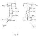
- Figure 6 is a sectional view along lines 6-6 in Figure 3 of the actuators.
- the conveyor includes a trough or pan 22 and two actuators 26a and 26b , one mounted to each lateral side of the trough 22 .
- the trough 22 may be supported by isolators (springs) that allow movement of the trough 22.
- the actuators 26a and 26b are mounted relative to the trough 22 at a selected angle (angle of attack). The resultant conveyor motion is at this angle and this causes the material to travel down the conveyor. The material is actually thrown a very short distance each time the conveyor moves back and forth. The total distance that the conveyor moves back and forth is known as the amplitude.
- Each actuator 26a and 26b comprise a motor 27a and 27b , respectively.
- the motors 27a, 27b have output shafts extending from opposite ends. Attached to each output shaft is an offset weight.
- the motors 27a, 27b rotate in opposite directions and are 180 degrees out-of-phase relative to each other. As the motors 26a, 27b rotate, the resulting centrifugal force causes the conveyor 20 to move back and forth in an oscillating motion. When the motor rotates, a centrifugal force is generated due to the weight being located off center from the motor shaft. If only one motor were used, the conveyor would move in a circular motion. By using two motors, rotating in opposite directions and out-of-phase, the conveyor motion becomes linear.
- the motor-weight assembly is also known as a shaker or inertial weight motor.
- the angle of attack of the conveyor affects the flow of material. At 45 degrees, the material speed and discharge rate (lb./hr.) will be the highest. Operating at angles less than 45 degrees causes the material to spread out more and a more uniform and steady flow rate results. When angles greater than 45 degrees are used, the material tends to move along in small piles. This causes the discharge rate to become less uniform. In addition, the greater the angle, the more noise is created.
- the conveyor structure is designed to withstand the forces generated by the actuators. This includes the forward and backward forces as well as the transverse forces.
- the present invention uses a single saddle plate to which both shaker motors are mounted. With this design, the transverse forces from one motor are canceled by transverse forces from the other motor, through the saddle plate. Because of this, no transverse forces are transmitted through welds connecting the actuators to the trough. The forward and backward forces are transmitted from the saddle plate to the conveyor trough using large gussets. Although these gussets are welded to the saddle plate and trough, the system permits a large weld to be used.
- the assembly 20 has a feed end 26 for receiving material and a discharge end 28 for delivering the material to a particular site.
- a pair of actuators 26a, 26b are coupled to a continuous saddle plate 30 by brackets 32 and 34 , respectively.
- Actuators 26a, 26b each include motors 27a, 27b , respectively. Extending from each end of each motor 27a, 27b , is an output shaft 28a, 29a, 28b, 29b . Attached to each output shaft 28a, 29a, 28b, 29b , is an offset weight 30a, 31a, 30b, 31b , respectively. Weights 30a and 31a rotate at the same rotational speed ⁇ as weights 30b and 31b but in an opposite direction and 180° out of phase. Due to this arrangement the transverse force created by actuator 26a are offset by the transverse force created by actuator 26b.
- the actuators 26a, 26b are coupled to saddle plate 30 by brackets 32 and 34 , respectively.
- the saddle plate 30 is couple to gussets 40 and 42 .
- the gussets 40 and 42 are in turn welded to the trough 4 .
- the orientation of the actuators 26a and 26b and the relationship of the respective weights is such that transverse forces of the individual motors cancel each other out.
- the placement of the saddle plate 30 on the trough, and the corresponding placement of the actuators should be selected for optimum movement of material.
- Figs. 3 and 5 provides a conveyor drive system which imparts a predominantly linear oscillating motion to the conveyor at a selected angle of attack (also known as stroke angle).
- Linear motion will cause the conveyor material to be thrown for short distances and thereby travel down the conveyor.
- the line of action should pass through the center of gravity of the conveyor. Otherwise. the conveyor motion will be non-linear.
- E the eccentric weight mass
- R the eccentric weight offset radius
- X the stroke (total peak-to-peak displacement occurring each operating cycle of the conveyor)
- M the mass of the conveyor trough 2 .
- a stroke of 1/4" is desired.
- the angle of attack or stroke angle ⁇ also affects the flow of material down the conveyor.
- the angle at which the actuator motors are mounted relative to the horizontal plane is the stroke angle.
- the resultant conveyor motion will be at this angle.
- At 45° the highest material speed will be achieved.
- the use of the saddle plate 30 eliminates the need for mounting the actuators directly to the trough as, for example, through welding. Transverse forces created by the individual motor are dissipated through the saddle plate 30 instead of welds of prior art systems. Due to the orientation and unitary construction of the saddle plate 30 , any transverse forces have less of an effect on the connection between the individual actuator 4 or 4' and the trough 2.
Landscapes
- Engineering & Computer Science (AREA)
- Mechanical Engineering (AREA)
- Jigging Conveyors (AREA)
Applications Claiming Priority (2)
| Application Number | Priority Date | Filing Date | Title |
|---|---|---|---|
| US09/025,010 US6041915A (en) | 1998-02-17 | 1998-02-17 | Vibratory conveyor with side-mounted drivers |
| US25010 | 1998-02-17 |
Publications (2)
| Publication Number | Publication Date |
|---|---|
| EP0936162A1 true EP0936162A1 (fr) | 1999-08-18 |
| EP0936162B1 EP0936162B1 (fr) | 2003-05-28 |
Family
ID=21823557
Family Applications (1)
| Application Number | Title | Priority Date | Filing Date |
|---|---|---|---|
| EP99300997A Expired - Lifetime EP0936162B1 (fr) | 1998-02-17 | 1999-02-11 | Convoyeur à vibrations avec des entraínements montés latéralement |
Country Status (10)
| Country | Link |
|---|---|
| US (1) | US6041915A (fr) |
| EP (1) | EP0936162B1 (fr) |
| JP (1) | JP3093193B2 (fr) |
| KR (1) | KR100287813B1 (fr) |
| AT (1) | ATE241547T1 (fr) |
| AU (1) | AU725064B2 (fr) |
| BR (1) | BR9900602A (fr) |
| CA (1) | CA2262062C (fr) |
| DE (1) | DE69908199T2 (fr) |
| ES (1) | ES2198848T3 (fr) |
Cited By (1)
| Publication number | Priority date | Publication date | Assignee | Title |
|---|---|---|---|---|
| DE102019119498A1 (de) * | 2019-07-18 | 2021-01-21 | Schaeffler Technologies AG & Co. KG | Fördertopf, Schwingfördervorrichtung mit dem Fördertopf sowie Verfahren zur Herstellung des Fördertopfes |
Families Citing this family (12)
| Publication number | Priority date | Publication date | Assignee | Title |
|---|---|---|---|---|
| WO2000023202A1 (fr) * | 1998-10-21 | 2000-04-27 | Manorex Limited | Ensemble vibreur |
| US6202832B1 (en) * | 1999-05-26 | 2001-03-20 | Fmc Corporation | Spring connection mechanism for vibratory feeders |
| US6659267B2 (en) * | 2000-11-04 | 2003-12-09 | Fmc Technologies, Inc. | Two-mass, base-excited conveyor |
| US6655523B2 (en) * | 2001-03-15 | 2003-12-02 | Key Technology, Inc. | Excited frame conveyor and excitation process for same |
| US6601695B1 (en) | 2002-01-02 | 2003-08-05 | Carrier Vibrating Equipment, Inc. | Differential motion conveyor drive |
| US7754984B2 (en) * | 2005-01-20 | 2010-07-13 | Ishida Co., Ltd. | Transportation device and combinational weighing apparatus including the same |
| JP5839452B2 (ja) * | 2011-08-23 | 2016-01-06 | 大和製衡株式会社 | 振動搬送装置及びそれを用いた粉粒体混合システム |
| US8733540B2 (en) * | 2012-10-10 | 2014-05-27 | Key Technology, Inc. | Excited frame vibratory conveyor |
| US9481525B1 (en) * | 2015-08-26 | 2016-11-01 | Key Technology, Inc. | Vibratory conveyor |
| WO2021226233A1 (fr) * | 2020-05-06 | 2021-11-11 | General Kinematics Corporation | Appareil vibratoire et système l'incorporant |
| CN112744518B (zh) * | 2021-01-25 | 2022-10-18 | 中国水利水电第九工程局有限公司 | 一种机制人工砂石振动给料施工方法 |
| DE102021121614B3 (de) | 2021-08-20 | 2022-10-13 | Heinrich Kühlert | Fördersystem sowie Verfahren zum Fördern von Schüttgut |
Citations (8)
| Publication number | Priority date | Publication date | Assignee | Title |
|---|---|---|---|---|
| FR1148331A (fr) * | 1955-05-05 | 1957-12-06 | Jost G M B H Schwingungstechni | Dispositif de commande de vibrations, en particulier pour installations transporteuses et tamis |
| US3061079A (en) * | 1958-11-28 | 1962-10-30 | Chain Belt Co | Tunable vibration exciter |
| DE1868501U (de) * | 1962-11-29 | 1963-03-07 | Meimberg G M B H | Vorrichtung zur schwingungserzeugung. |
| US3346097A (en) * | 1965-10-20 | 1967-10-10 | Co Louisville Trust | Adjustable stroke vibratory feeder |
| US3348664A (en) * | 1966-01-21 | 1967-10-24 | Adamson Stephens Mfg Co | Natural frequency vibrating feeder |
| DE1272608B (de) * | 1955-05-05 | 1968-07-11 | Joest G M B H Schwingungstechn | Von Unwuchterregern angetriebenes Schwingarbeitsgeraet |
| GB2301075A (en) * | 1995-05-24 | 1996-11-27 | British American Tobacco Co | Vibratory conveying of tobacco |
| FR2741054A1 (fr) * | 1995-11-10 | 1997-05-16 | Le Floch Ets | Convoyeur vibrant |
Family Cites Families (14)
| Publication number | Priority date | Publication date | Assignee | Title |
|---|---|---|---|---|
| US29512A (en) * | 1860-08-07 | Holder fob | ||
| US2913912A (en) * | 1954-07-20 | 1959-11-24 | Steinmueller Gmbh L & C | Fuel feed regulation for vibratory combustion grates |
| US2948419A (en) * | 1957-09-16 | 1960-08-09 | Rca Corp | Article orienting and stacking device |
| US3014587A (en) * | 1959-08-24 | 1961-12-26 | Syntron Co | Vibratory screen with single unbalanced vibratory motor |
| US3226989A (en) * | 1961-11-07 | 1966-01-04 | Litton Industries Inc | Vibratory screen systems |
| US3212629A (en) * | 1963-04-23 | 1965-10-19 | Kloeckner Humboldt Deutz Ag | Vibratory conveyor, particularly bin-discharge conveyor |
| US3604555A (en) * | 1968-07-15 | 1971-09-14 | Gerald Cowper | Vibratory conveyor |
| US3796299A (en) | 1971-07-08 | 1974-03-12 | Gen Kinematics Corp | Vibratory material handling device with variable force application |
| US4632751A (en) * | 1982-11-15 | 1986-12-30 | Johnson Louis W | Shaker screen |
| SU1301749A1 (ru) * | 1985-11-25 | 1987-04-07 | Специальное Конструкторское Бюро По Подземному Самоходному Горному Оборудованию-Скб@ Гормаш | Вибрационный бункерный питатель дл сыпучего материала |
| DE3622675A1 (de) * | 1986-07-05 | 1988-01-14 | Joest Gmbh & Co Kg | Schwingfoerderrinne fuer kraetze |
| US5213200A (en) * | 1992-03-25 | 1993-05-25 | Inductotherm Corp. | Vibratory flow feed conveyor with removable pan |
| US5265730A (en) * | 1992-04-06 | 1993-11-30 | Sweco, Incorporated | Vibratory screen separator |
| US5762176A (en) * | 1996-11-08 | 1998-06-09 | Fmc Corporation | Belt driven vibratory apparatus |
-
1998
- 1998-02-17 US US09/025,010 patent/US6041915A/en not_active Expired - Lifetime
-
1999
- 1999-02-05 AU AU15423/99A patent/AU725064B2/en not_active Ceased
- 1999-02-11 AT AT99300997T patent/ATE241547T1/de not_active IP Right Cessation
- 1999-02-11 DE DE69908199T patent/DE69908199T2/de not_active Expired - Lifetime
- 1999-02-11 ES ES99300997T patent/ES2198848T3/es not_active Expired - Lifetime
- 1999-02-11 EP EP99300997A patent/EP0936162B1/fr not_active Expired - Lifetime
- 1999-02-11 BR BR9900602-2A patent/BR9900602A/pt not_active Application Discontinuation
- 1999-02-16 JP JP11037933A patent/JP3093193B2/ja not_active Expired - Fee Related
- 1999-02-17 CA CA002262062A patent/CA2262062C/fr not_active Expired - Fee Related
- 1999-02-18 KR KR1019990005372A patent/KR100287813B1/ko not_active Expired - Fee Related
Patent Citations (8)
| Publication number | Priority date | Publication date | Assignee | Title |
|---|---|---|---|---|
| FR1148331A (fr) * | 1955-05-05 | 1957-12-06 | Jost G M B H Schwingungstechni | Dispositif de commande de vibrations, en particulier pour installations transporteuses et tamis |
| DE1272608B (de) * | 1955-05-05 | 1968-07-11 | Joest G M B H Schwingungstechn | Von Unwuchterregern angetriebenes Schwingarbeitsgeraet |
| US3061079A (en) * | 1958-11-28 | 1962-10-30 | Chain Belt Co | Tunable vibration exciter |
| DE1868501U (de) * | 1962-11-29 | 1963-03-07 | Meimberg G M B H | Vorrichtung zur schwingungserzeugung. |
| US3346097A (en) * | 1965-10-20 | 1967-10-10 | Co Louisville Trust | Adjustable stroke vibratory feeder |
| US3348664A (en) * | 1966-01-21 | 1967-10-24 | Adamson Stephens Mfg Co | Natural frequency vibrating feeder |
| GB2301075A (en) * | 1995-05-24 | 1996-11-27 | British American Tobacco Co | Vibratory conveying of tobacco |
| FR2741054A1 (fr) * | 1995-11-10 | 1997-05-16 | Le Floch Ets | Convoyeur vibrant |
Cited By (3)
| Publication number | Priority date | Publication date | Assignee | Title |
|---|---|---|---|---|
| DE102019119498A1 (de) * | 2019-07-18 | 2021-01-21 | Schaeffler Technologies AG & Co. KG | Fördertopf, Schwingfördervorrichtung mit dem Fördertopf sowie Verfahren zur Herstellung des Fördertopfes |
| WO2021008646A1 (fr) | 2019-07-18 | 2021-01-21 | Schaeffler Technologies AG & Co. KG | Bol de distribution, dispositif de distribution vibrant pourvu du bol de distribution ainsi que procédé pour fabriquer le bol de distribution |
| US11905119B2 (en) | 2019-07-18 | 2024-02-20 | Schaeffler Technologies AG & Co. KG | Conveyor bowl, vibratory conveyor device having the conveyor bowl, and method for producing the conveyor bowl |
Also Published As
| Publication number | Publication date |
|---|---|
| US6041915A (en) | 2000-03-28 |
| KR19990072718A (ko) | 1999-09-27 |
| ES2198848T3 (es) | 2004-02-01 |
| AU725064B2 (en) | 2000-10-05 |
| CA2262062C (fr) | 2003-11-11 |
| CA2262062A1 (fr) | 1999-08-17 |
| BR9900602A (pt) | 2000-02-29 |
| DE69908199T2 (de) | 2003-11-27 |
| AU1542399A (en) | 1999-09-23 |
| JP3093193B2 (ja) | 2000-10-03 |
| ATE241547T1 (de) | 2003-06-15 |
| KR100287813B1 (ko) | 2001-04-16 |
| DE69908199D1 (de) | 2003-07-03 |
| EP0936162B1 (fr) | 2003-05-28 |
| JPH11314726A (ja) | 1999-11-16 |
Similar Documents
| Publication | Publication Date | Title |
|---|---|---|
| EP0936162B1 (fr) | Convoyeur à vibrations avec des entraínements montés latéralement | |
| US5131525A (en) | Vibratory conveyor | |
| US6415913B2 (en) | Excited base conveyor system | |
| US20110083944A1 (en) | Vibratory conveyor | |
| US3251457A (en) | Method and apparatus for driving vibratory devices | |
| US7387198B2 (en) | Balanced flat stroke bi-directional conveyor | |
| KR19990072906A (ko) | 진동컨베이어 | |
| US3528541A (en) | Balanced oscillating conveyor | |
| US2535050A (en) | Vibratory conveyer | |
| US4428476A (en) | Vibratory apparatus | |
| CA2191873C (fr) | Dispositif de support de convoyeur pour deplacement rectiligne | |
| JP2005041692A (ja) | 湾曲通路内において物品を搬送するための振動式フィーダ | |
| US4880106A (en) | Electromagnetic vibratory feeder | |
| JPS6115003B2 (fr) | ||
| US3212629A (en) | Vibratory conveyor, particularly bin-discharge conveyor | |
| MXPA99001619A (en) | Vibratory conveying band with lateralme mounted drivers | |
| US3346097A (en) | Adjustable stroke vibratory feeder | |
| JPS6030246Y2 (ja) | 振動コンベア | |
| US3029924A (en) | Vibrating feeder | |
| JPS5849442B2 (ja) | 振動コンベア | |
| CS234528B1 (cs) | Vibrační zařízení pro dopravu sypkých materiálů | |
| RU1792897C (ru) | Вибрационный конвейер | |
| JPS5832124B2 (ja) | 振動部品搬送機 | |
| JPS6016570Y2 (ja) | 振動コンベア | |
| JPS6052046B2 (ja) | 振動部品供給機 |
Legal Events
| Date | Code | Title | Description |
|---|---|---|---|
| PUAI | Public reference made under article 153(3) epc to a published international application that has entered the european phase |
Free format text: ORIGINAL CODE: 0009012 |
|
| 17P | Request for examination filed |
Effective date: 19990301 |
|
| AK | Designated contracting states |
Kind code of ref document: A1 Designated state(s): AT BE CH DE ES FR GB IT LI LU NL |
|
| AX | Request for extension of the european patent |
Free format text: AL;LT;LV;MK;RO;SI |
|
| AKX | Designation fees paid |
Free format text: AT BE CH DE ES FR GB IT LI LU NL |
|
| 17Q | First examination report despatched |
Effective date: 20001127 |
|
| GRAG | Despatch of communication of intention to grant |
Free format text: ORIGINAL CODE: EPIDOS AGRA |
|
| GRAG | Despatch of communication of intention to grant |
Free format text: ORIGINAL CODE: EPIDOS AGRA |
|
| GRAH | Despatch of communication of intention to grant a patent |
Free format text: ORIGINAL CODE: EPIDOS IGRA |
|
| GRAG | Despatch of communication of intention to grant |
Free format text: ORIGINAL CODE: EPIDOS AGRA |
|
| GRAH | Despatch of communication of intention to grant a patent |
Free format text: ORIGINAL CODE: EPIDOS IGRA |
|
| GRAA | (expected) grant |
Free format text: ORIGINAL CODE: 0009210 |
|
| AK | Designated contracting states |
Designated state(s): AT BE CH DE ES FR GB IT LI LU NL |
|
| PG25 | Lapsed in a contracting state [announced via postgrant information from national office to epo] |
Ref country code: NL Free format text: LAPSE BECAUSE OF FAILURE TO SUBMIT A TRANSLATION OF THE DESCRIPTION OR TO PAY THE FEE WITHIN THE PRESCRIBED TIME-LIMIT Effective date: 20030528 Ref country code: LI Free format text: LAPSE BECAUSE OF FAILURE TO SUBMIT A TRANSLATION OF THE DESCRIPTION OR TO PAY THE FEE WITHIN THE PRESCRIBED TIME-LIMIT Effective date: 20030528 Ref country code: CH Free format text: LAPSE BECAUSE OF FAILURE TO SUBMIT A TRANSLATION OF THE DESCRIPTION OR TO PAY THE FEE WITHIN THE PRESCRIBED TIME-LIMIT Effective date: 20030528 |
|
| REG | Reference to a national code |
Ref country code: GB Ref legal event code: FG4D |
|
| REG | Reference to a national code |
Ref country code: CH Ref legal event code: EP |
|
| REF | Corresponds to: |
Ref document number: 69908199 Country of ref document: DE Date of ref document: 20030703 Kind code of ref document: P |
|
| NLV1 | Nl: lapsed or annulled due to failure to fulfill the requirements of art. 29p and 29m of the patents act | ||
| REG | Reference to a national code |
Ref country code: CH Ref legal event code: PL |
|
| REG | Reference to a national code |
Ref country code: ES Ref legal event code: FG2A Ref document number: 2198848 Country of ref document: ES Kind code of ref document: T3 |
|
| PG25 | Lapsed in a contracting state [announced via postgrant information from national office to epo] |
Ref country code: LU Free format text: LAPSE BECAUSE OF NON-PAYMENT OF DUE FEES Effective date: 20040211 |
|
| ET | Fr: translation filed | ||
| PLBE | No opposition filed within time limit |
Free format text: ORIGINAL CODE: 0009261 |
|
| STAA | Information on the status of an ep patent application or granted ep patent |
Free format text: STATUS: NO OPPOSITION FILED WITHIN TIME LIMIT |
|
| 26N | No opposition filed |
Effective date: 20040302 |
|
| PGFP | Annual fee paid to national office [announced via postgrant information from national office to epo] |
Ref country code: ES Payment date: 20100312 Year of fee payment: 12 |
|
| PGFP | Annual fee paid to national office [announced via postgrant information from national office to epo] |
Ref country code: IT Payment date: 20100220 Year of fee payment: 12 Ref country code: FR Payment date: 20100223 Year of fee payment: 12 |
|
| PGFP | Annual fee paid to national office [announced via postgrant information from national office to epo] |
Ref country code: GB Payment date: 20100202 Year of fee payment: 12 Ref country code: DE Payment date: 20100219 Year of fee payment: 12 Ref country code: BE Payment date: 20100215 Year of fee payment: 12 Ref country code: AT Payment date: 20100212 Year of fee payment: 12 |
|
| BERE | Be: lapsed |
Owner name: *INDUCTOTHERM CORP. Effective date: 20110228 |
|
| GBPC | Gb: european patent ceased through non-payment of renewal fee |
Effective date: 20110211 |
|
| REG | Reference to a national code |
Ref country code: FR Ref legal event code: ST Effective date: 20111102 |
|
| PG25 | Lapsed in a contracting state [announced via postgrant information from national office to epo] |
Ref country code: AT Free format text: LAPSE BECAUSE OF NON-PAYMENT OF DUE FEES Effective date: 20110211 Ref country code: BE Free format text: LAPSE BECAUSE OF NON-PAYMENT OF DUE FEES Effective date: 20110228 |
|
| PG25 | Lapsed in a contracting state [announced via postgrant information from national office to epo] |
Ref country code: IT Free format text: LAPSE BECAUSE OF NON-PAYMENT OF DUE FEES Effective date: 20110211 |
|
| REG | Reference to a national code |
Ref country code: DE Ref legal event code: R119 Ref document number: 69908199 Country of ref document: DE Effective date: 20110901 |
|
| PG25 | Lapsed in a contracting state [announced via postgrant information from national office to epo] |
Ref country code: FR Free format text: LAPSE BECAUSE OF NON-PAYMENT OF DUE FEES Effective date: 20110228 |
|
| PG25 | Lapsed in a contracting state [announced via postgrant information from national office to epo] |
Ref country code: GB Free format text: LAPSE BECAUSE OF NON-PAYMENT OF DUE FEES Effective date: 20110211 |
|
| REG | Reference to a national code |
Ref country code: ES Ref legal event code: FD2A Effective date: 20120411 |
|
| PG25 | Lapsed in a contracting state [announced via postgrant information from national office to epo] |
Ref country code: ES Free format text: LAPSE BECAUSE OF NON-PAYMENT OF DUE FEES Effective date: 20110212 |
|
| PG25 | Lapsed in a contracting state [announced via postgrant information from national office to epo] |
Ref country code: DE Free format text: LAPSE BECAUSE OF NON-PAYMENT OF DUE FEES Effective date: 20110901 |