EP0936178B1 - Batteriebetriebenes Flurförderzeug - Google Patents
Batteriebetriebenes Flurförderzeug Download PDFInfo
- Publication number
- EP0936178B1 EP0936178B1 EP99101225A EP99101225A EP0936178B1 EP 0936178 B1 EP0936178 B1 EP 0936178B1 EP 99101225 A EP99101225 A EP 99101225A EP 99101225 A EP99101225 A EP 99101225A EP 0936178 B1 EP0936178 B1 EP 0936178B1
- Authority
- EP
- European Patent Office
- Prior art keywords
- battery
- industrial vehicle
- battery box
- body frame
- hood
- Prior art date
- Legal status (The legal status is an assumption and is not a legal conclusion. Google has not performed a legal analysis and makes no representation as to the accuracy of the status listed.)
- Expired - Lifetime
Links
- 230000005484 gravity Effects 0.000 description 10
- 239000010720 hydraulic oil Substances 0.000 description 4
- 238000004519 manufacturing process Methods 0.000 description 2
- 239000003921 oil Substances 0.000 description 2
- 230000002441 reversible effect Effects 0.000 description 2
- ZRXYMHTYEQQBLN-UHFFFAOYSA-N [Br].[Zn] Chemical compound [Br].[Zn] ZRXYMHTYEQQBLN-UHFFFAOYSA-N 0.000 description 1
- BNOODXBBXFZASF-UHFFFAOYSA-N [Na].[S] Chemical compound [Na].[S] BNOODXBBXFZASF-UHFFFAOYSA-N 0.000 description 1
- 230000008602 contraction Effects 0.000 description 1
- 230000003247 decreasing effect Effects 0.000 description 1
- 230000000694 effects Effects 0.000 description 1
- 238000009434 installation Methods 0.000 description 1
- 230000002452 interceptive effect Effects 0.000 description 1
- 230000002829 reductive effect Effects 0.000 description 1
- 230000000717 retained effect Effects 0.000 description 1
Images




Classifications
-
- B—PERFORMING OPERATIONS; TRANSPORTING
- B66—HOISTING; LIFTING; HAULING
- B66F—HOISTING, LIFTING, HAULING OR PUSHING, NOT OTHERWISE PROVIDED FOR, e.g. DEVICES WHICH APPLY A LIFTING OR PUSHING FORCE DIRECTLY TO THE SURFACE OF A LOAD
- B66F9/00—Devices for lifting or lowering bulky or heavy goods for loading or unloading purposes
- B66F9/06—Devices for lifting or lowering bulky or heavy goods for loading or unloading purposes movable, with their loads, on wheels or the like, e.g. fork-lift trucks
-
- B—PERFORMING OPERATIONS; TRANSPORTING
- B60—VEHICLES IN GENERAL
- B60K—ARRANGEMENT OR MOUNTING OF PROPULSION UNITS OR OF TRANSMISSIONS IN VEHICLES; ARRANGEMENT OR MOUNTING OF PLURAL DIVERSE PRIME-MOVERS IN VEHICLES; AUXILIARY DRIVES FOR VEHICLES; INSTRUMENTATION OR DASHBOARDS FOR VEHICLES; ARRANGEMENTS IN CONNECTION WITH COOLING, AIR INTAKE, GAS EXHAUST OR FUEL SUPPLY OF PROPULSION UNITS IN VEHICLES
- B60K1/00—Arrangement or mounting of electrical propulsion units
- B60K1/04—Arrangement or mounting of electrical propulsion units of the electric storage means for propulsion
-
- B—PERFORMING OPERATIONS; TRANSPORTING
- B60—VEHICLES IN GENERAL
- B60L—PROPULSION OF ELECTRICALLY-PROPELLED VEHICLES; SUPPLYING ELECTRIC POWER FOR AUXILIARY EQUIPMENT OF ELECTRICALLY-PROPELLED VEHICLES; ELECTRODYNAMIC BRAKE SYSTEMS FOR VEHICLES IN GENERAL; MAGNETIC SUSPENSION OR LEVITATION FOR VEHICLES; MONITORING OPERATING VARIABLES OF ELECTRICALLY-PROPELLED VEHICLES; ELECTRIC SAFETY DEVICES FOR ELECTRICALLY-PROPELLED VEHICLES
- B60L53/00—Methods of charging batteries, specially adapted for electric vehicles; Charging stations or on-board charging equipment therefor; Exchange of energy storage elements in electric vehicles
- B60L53/80—Exchanging energy storage elements, e.g. removable batteries
-
- B—PERFORMING OPERATIONS; TRANSPORTING
- B66—HOISTING; LIFTING; HAULING
- B66F—HOISTING, LIFTING, HAULING OR PUSHING, NOT OTHERWISE PROVIDED FOR, e.g. DEVICES WHICH APPLY A LIFTING OR PUSHING FORCE DIRECTLY TO THE SURFACE OF A LOAD
- B66F9/00—Devices for lifting or lowering bulky or heavy goods for loading or unloading purposes
- B66F9/06—Devices for lifting or lowering bulky or heavy goods for loading or unloading purposes movable, with their loads, on wheels or the like, e.g. fork-lift trucks
- B66F9/075—Constructional features or details
- B66F9/07513—Details concerning the chassis
- B66F9/07531—Battery compartments
-
- H—ELECTRICITY
- H01—ELECTRIC ELEMENTS
- H01M—PROCESSES OR MEANS, e.g. BATTERIES, FOR THE DIRECT CONVERSION OF CHEMICAL ENERGY INTO ELECTRICAL ENERGY
- H01M50/00—Constructional details or processes of manufacture of the non-active parts of electrochemical cells other than fuel cells, e.g. hybrid cells
- H01M50/20—Mountings; Secondary casings or frames; Racks, modules or packs; Suspension devices; Shock absorbers; Transport or carrying devices; Holders
- H01M50/204—Racks, modules or packs for multiple batteries or multiple cells
- H01M50/207—Racks, modules or packs for multiple batteries or multiple cells characterised by their shape
- H01M50/209—Racks, modules or packs for multiple batteries or multiple cells characterised by their shape adapted for prismatic or rectangular cells
-
- H—ELECTRICITY
- H01—ELECTRIC ELEMENTS
- H01M—PROCESSES OR MEANS, e.g. BATTERIES, FOR THE DIRECT CONVERSION OF CHEMICAL ENERGY INTO ELECTRICAL ENERGY
- H01M50/00—Constructional details or processes of manufacture of the non-active parts of electrochemical cells other than fuel cells, e.g. hybrid cells
- H01M50/20—Mountings; Secondary casings or frames; Racks, modules or packs; Suspension devices; Shock absorbers; Transport or carrying devices; Holders
- H01M50/249—Mountings; Secondary casings or frames; Racks, modules or packs; Suspension devices; Shock absorbers; Transport or carrying devices; Holders specially adapted for aircraft or vehicles, e.g. cars or trains
-
- H—ELECTRICITY
- H01—ELECTRIC ELEMENTS
- H01M—PROCESSES OR MEANS, e.g. BATTERIES, FOR THE DIRECT CONVERSION OF CHEMICAL ENERGY INTO ELECTRICAL ENERGY
- H01M50/00—Constructional details or processes of manufacture of the non-active parts of electrochemical cells other than fuel cells, e.g. hybrid cells
- H01M50/20—Mountings; Secondary casings or frames; Racks, modules or packs; Suspension devices; Shock absorbers; Transport or carrying devices; Holders
- H01M50/271—Lids or covers for the racks or secondary casings
-
- Y—GENERAL TAGGING OF NEW TECHNOLOGICAL DEVELOPMENTS; GENERAL TAGGING OF CROSS-SECTIONAL TECHNOLOGIES SPANNING OVER SEVERAL SECTIONS OF THE IPC; TECHNICAL SUBJECTS COVERED BY FORMER USPC CROSS-REFERENCE ART COLLECTIONS [XRACs] AND DIGESTS
- Y02—TECHNOLOGIES OR APPLICATIONS FOR MITIGATION OR ADAPTATION AGAINST CLIMATE CHANGE
- Y02E—REDUCTION OF GREENHOUSE GAS [GHG] EMISSIONS, RELATED TO ENERGY GENERATION, TRANSMISSION OR DISTRIBUTION
- Y02E60/00—Enabling technologies; Technologies with a potential or indirect contribution to GHG emissions mitigation
- Y02E60/10—Energy storage using batteries
-
- Y—GENERAL TAGGING OF NEW TECHNOLOGICAL DEVELOPMENTS; GENERAL TAGGING OF CROSS-SECTIONAL TECHNOLOGIES SPANNING OVER SEVERAL SECTIONS OF THE IPC; TECHNICAL SUBJECTS COVERED BY FORMER USPC CROSS-REFERENCE ART COLLECTIONS [XRACs] AND DIGESTS
- Y02—TECHNOLOGIES OR APPLICATIONS FOR MITIGATION OR ADAPTATION AGAINST CLIMATE CHANGE
- Y02T—CLIMATE CHANGE MITIGATION TECHNOLOGIES RELATED TO TRANSPORTATION
- Y02T10/00—Road transport of goods or passengers
- Y02T10/60—Other road transportation technologies with climate change mitigation effect
- Y02T10/70—Energy storage systems for electromobility, e.g. batteries
-
- Y—GENERAL TAGGING OF NEW TECHNOLOGICAL DEVELOPMENTS; GENERAL TAGGING OF CROSS-SECTIONAL TECHNOLOGIES SPANNING OVER SEVERAL SECTIONS OF THE IPC; TECHNICAL SUBJECTS COVERED BY FORMER USPC CROSS-REFERENCE ART COLLECTIONS [XRACs] AND DIGESTS
- Y02—TECHNOLOGIES OR APPLICATIONS FOR MITIGATION OR ADAPTATION AGAINST CLIMATE CHANGE
- Y02T—CLIMATE CHANGE MITIGATION TECHNOLOGIES RELATED TO TRANSPORTATION
- Y02T10/00—Road transport of goods or passengers
- Y02T10/60—Other road transportation technologies with climate change mitigation effect
- Y02T10/7072—Electromobility specific charging systems or methods for batteries, ultracapacitors, supercapacitors or double-layer capacitors
Definitions
- the present invention relates to industrial vehicles such as forklifts having a battery, and more specifically, to a battery location.
- battery-powered forklifts are divided into two types according to the location of the battery. As shown in Figs. 7 and 8 , in one type of forklift 60, which is mainly used in Japan, part of a battery 61 is located above rear wheels 62. Parts of the steering mechanism (not shown) are located below the battery 61. A battery hood 63, which opens and closes, is located over the battery 61. A seat 64 is provided above the battery hood 63.
- a battery 61 is located between the front wheels 65 and rear wheels 62.
- the lower part of the battery 61 extends to the vicinity of a vehicle frame 66. Accordingly, the size of the battery 61 of the European-type forklift 60 can be larger than that of the Japanese-type forklift 60. Further, the center of gravity of the European-type forklift 60 is lower, and the European-type forklift 60 is thus more stable than the Japanese-type forklift 60.
- the battery-powered forklifts Compared to engine-powered forklifts, the battery-powered forklifts have less space in the driver's compartment, especially at the feet of the driver, because the battery 61 occupies a large space. Further, the battery 61, which is a rectangular parallelepiped, has substantially the same width as that of the vehicle body 66. The upper surface of the battery 61 reaches the vicinity of the seat 64. The battery hood 63 has a shape substantially corresponding to the shape of the battery 61. Therefore, compared to the engine-powered forklift, the driver has trouble in getting in and out of the driver's compartment 67 due to the corner of the battery hood 63.
- the driver's room is increased by positioning part of the battery 61 above the rear wheels 62.
- the center of gravity of the Japanese-type forklift 60 is higher than that of the European-type forklift 60, the stability of the Japanese-type is lower.
- the battery 61 of the European-type forklift 60 is located more forward than that of the Japanese-type forklift 60. Therefore, the driver's foot room in the European-type is smaller than that of the Japanese-type, and a step 68 is relatively small.
- the driver When loading and unloading a truck using the forklift 60, the driver must frequently get in and out of the forklift 60.
- the narrow compartment 67 and the small step 68 inconvenience the driver, and work efficiency is lowered.
- EP0030928 Another arrangement of the battery in an industrial track is disclosed in EP0030928 .
- An objective of the present invention is to provide a stable battery-powered industrial vehicle that facilitates getting in and out of the vehicle.
- the present invention provides an industrial vehicle driven by a battery as defined in claim 1.
- the present invention also includes a forklift driven by a battery as defined in claim 12.
- a pair of masts 2 is attached to the front portion of a body frame 1a of a battery-type forklift 1.
- a fork 3 is slidably supported by the masts 2 through a lift bracket 3a.
- the fork 3 moves up and down with the lift bracket 3a along the masts 2 by the expansion and contraction of a lift cylinder 4.
- Four supports 5 are provided on the body frame 1a.
- a head-guard 5a is provided on the top end of the supports 5.
- a driver's compartment 6 is defined in the space surrounded by the supports 5 and the head-guard 5a.
- a battery box 7 for accommodating a battery 15 is provided below the driver's compartment 6.
- the body frame 1a forms the battery box 7 between the front wheels 8 and the rear wheels 9.
- the battery box 7 is lower than the floor board 11 that supports the driver's legs. Further, the front end of the battery box extends forward to a position that corresponds to the front end of the floor board 11.
- the battery 15 in the battery box 7 has substantially the same volume as that in the forklift shown in Figs. 7 and 8 .
- the battery box is symmetrical about a vertical longitudinal plane and is substantially T-shaped.
- the rear portion of the battery box 7 has substantially the same width as that of the body frame 1a, and the front portion of the battery box 7 has a narrower width than that of the rear portion.
- the longitudinal axis of the battery box 7 is preferably vertically aligned with that of the body frame 1a.
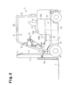
- the steps 12 are formed on the narrow portion of the battery box 7, that is, on the sides of the front portion. As shown in Fig. 3 , the steps 12 are located below the floor board 11.
- the battery 15 is made of a plurality of battery cells 14 held in a case 13.
- the battery 15 is a lead storage battery.
- the battery case 13 is formed to correspond to the shape of the box 7.
- the number of battery cells 14 varies in accordance with the amount of current and electric power required by the forklift 1.
- the number of battery cells 14 in the battery case 13 is enough to supply the necessary electric current and power. In the illustrated embodiment, twenty-four battery cells 14 are used.
- Each battery cell 14 produces two volts of electromotive force. Forty-eight volts are produced by serially connecting the battery cells 14.
- the battery case 13 includes a main rectangular case 13a, which accommodates twenty battery cells, and a pair of sub cases 13b, each of which accommodates two battery cells 14.
- the sub cases 13b are welded to the sides of the main case 13a as shown in Fig. 2 .
- the battery case also includes a lifting hole (not shown) for permitting a lifting cable (not shown) to be attached for lifting the battery 15.
- the lifting hole is located above the upper end of the battery box 7 since the upper end of the battery case 13 projects slightly higher than the upper end of the battery box 7.
- a battery hood 16 covers the rear portion of an upper opening 7a of the battery box 7, and the front portion is covered by the floor board 11.
- the floor board 11 is detachably fixed to the body frame 1a by bolts or screws (not shown). When changing the battery 15, detaching the floor board 11 opens the upper opening 7a. As shown by the chain line in Fig. 4 , both sides of the floor board 11 are bent downward.
- the rear portion of the battery hood 16 is pivotally supported on the body frame 1a through a pair of hinges 17 (See Fig. 4 ).
- the battery hood 16 includes an upper wall 16a, which is horizontal when closed, a front wall 16b and a pair of side walls 16c, which are connected to the upper wall 16a.
- a seat 10 is secured on the upper wall 16a.
- the battery hood 16 covers the rear portion of the box 7. When the battery hood 16 is closed, the lower rim of the front wall 16b abuts on the upper surface of the floor board 11. Each of the front corners of the battery hood 16, which are virtually aligned with the rear of the steps 12, has a large radius of curvature. To make the height of the seat 10 substantially the same as that of the prior art seat 64 shown in Figs. 8 and 10 , the side walls 16c of the battery hood 16 extend higher than those of the prior art battery hood 63.
- An engaging portion (not shown) is provided on one of the side walls 16c of the battery hood 16.
- the floor board 11 includes an engaging portion and an engageabe catch (not shown). When the battery hood 16 is closed, the engaging portion engages the catch.
- a damper (not shown) is provided between the inner side of the battery hood 16 and the body frame 1a. The damper permits the battery hood 16 to be opened and closed with a small force.
- a motor 18 for driving the front wheels 8 is provided in the front of the battery box 7.
- the motor 18 drives the front wheels 8 through a differential 19a and other gears (not shown).
- the rear wheels 9 are steered by a hydraulic power steering apparatus (not shown), which is provided behind the battery 15.
- Oil tanks 21, which are used for hydraulic operation of the forklift 1 and the power steering apparatus, are provided below the steps 12.
- Supporting members 23, which transfer the force applied by a hydraulic tilt cylinder 22 to the body frame 1a, are arranged to surround the oil tanks 21.
- the center of gravity of the vehicle body is relatively low. Since the battery 15 is located more forward than that of the Japanese-type forklift 60, the stability of the vehicle body would be reduced if the height of the gravity center remained the same. However, the effect of lowering the center of gravity of the forklift 1 is greater than that of moving the gravity center forward. Therefore, the vehicle is more stable than the prior art models.
- the battery hood 16 is kept closed except when the battery 15 is replaced or checked.
- the catch is first released, and the battery hood 16 is released.
- the damper urges the battery hood 16 open, and the battery hood abuts against a rubber cushion (not shown) on the support 5.
- a known lock mechanism (not shown) locks the battery hood 16 at the open position.
- the lock mechanism locks the battery hood 16 when the battery hood 16 is fully opened. A driver releases the lock mechanism when closing the battery hood 16.
- the floor board 11 covering the upper opening 7a is taken off and the upper opening 7a is fully opened.
- a lifting cable is hooked in the lifting hole of the battery case 13, and a crane lifts the battery case 13 from the battery box 7 with the cable.
- the battery case 13 is moved laterally and is loaded on a carrier vehicle (not shown).
- the present invention has the following advantages.
- the present invention is not limited to the above embodiment, but further be embodied as follows.
- a battery box 7, which is narrower than the vehicle and regular in shape, may be offset to one side (the right side in this embodiment).
- a step 12 is formed on one side of the vehicle (the left side in this embodiment).
- Five battery cells 14 can be arranged widthwise and five cells 14 can be arranged lengthwise in the battery case 13, thus the battery case 13 can accommodate twenty-five battery cells in total.
- a space corresponding to the size of one battery cell is formed at a corner of the battery case 13.
- the shape and position of the step 12 and the structure of the battery hood 16 are the same as those of the first embodiment.
- the hydraulic oil tank is located below the step 12 and leftward of the battery box 7.
- the embodiment of Fig.5 has the advantages (1)-(4) and (9)-(13) of the first embodiment.
- the battery box 7 is square. Accordingly, the battery case 13 is formed with one box, and this facilitates the manufacturing of the battery case 13. Also, it is easier to balance the battery case when raising it, in comparison to the first embodiment. Further, the space on the left side of the battery box 7 and the corner space in the battery box 7 can be used for other purposes.
- the width of the rear portion of the battery box 7 may be substantially the same as that of the vehicle, and a step 12 may be formed on one side (left side in Fig. 6 ) of the front portion. In this case, the width of the step 12 can be increased.
- the upper edge of the battery box 7 may be located at the same height as that of the step 12, and the battery case 13 may extend above the battery box 7 to a point just below the lower surface of the floor board 11.
- the upper portion of the battery case 13 is covered with the floor board 11 and the battery hood 16, and part of the side surface of the battery case 13 is exposed on both sides of the forklift 1.
- the battery case 13 when taking out the battery 15 from the battery box 7, the battery case 13 needs only to be raised a little higher than the upper surface of the step 12 before being moved laterally. Accordingly, the battery 15 does not interfere with the steering column and equipment in the driver's compartment 6 such as an instrument panel. This facilitates battery replacement.
- the height of the upper edge of the battery box 7 may be lower than that of the step 12.
- the battery case is less likely to interfere with the equipment in the driver's compartment since the battery case 13 does not need to be lifted very high before it is removed.
- a detachable side panel may be provided on the side of the forklift 1 to cover the side surface of the battery 15. In this case, the side panel is taken off when replacing the battery 15.
- the side panel may be constructed such that it can open and close, and the battery 15 is replaced when the side panel is opened.
- the floor board 11 may be structured to open and close on hinges.
- the hinges may be provided either on the body frame 1a or on the battery hood 16. In this case, there is no need to use bolts or screws to secure the floor board.
- the battery case 13 may be replaced by several cases, or preferably, two cases.
- each of the battery cases 13 shown in Figs. 2 and 6 may be replaced by two types of cases.
- One case accommodates battery cells 14 in a two-by-six arrangement, and the other accommodates battery cells 14 in a three-by-four arrangement.
- the battery case 13 of Fig. 5 may be replaced by a case that accommodates battery cells 14 in a three-by-five arrangement and a case that accommodates battery cells 14 in a two-by-five arrangement.
- the rear battery case is taken out first, and then the front battery case is taken out.
- the case is first moved backward, then, the case is lifted and moved laterally. Battery installation is done in the reverse order. In this way, battery replacement is less likely to interfere with the equipment in the driver's compartment.
- the hydraulic oil tank 21 may be formed by the body frame 1a and the supporting members 23. In this case, it is not necessary to install a hydraulic oil tank between the body frame 1a and the supporting members 23.
- the supporting members 23 can be omitted if the body frame 1a is strengthened.
- the location of the engaging portion and the catch for retaining the battery hood 16 in a closed position may be varied.
- the engaging portion may be provided on the front wall 16b of the battery hood 16, and the catch may be provided at a position corresponding to the engaging portion.
- the retaining mechanism may be other known types of fasteners.
- engaging portions may be provided at several positions.
- the battery hood 16 may be retained in a closed position by its weight without any retaining mechanism.
- the damper for reducing the force needed for opening and closing the battery hood 16 may be omitted, and a retaining mechanism that retains the battery hood 16 in an open position may be provided.
- the battery box 7 may have a uniform width that is the same as the narrow portion between the steps 12. In this case also, the stability of the vehicle is improved and getting in and out of the vehicle is facilitated.
- the direction of movement of the battery hood may be vertical or horizontal.
- the battery 15 is not limited to a lead storage battery.
- the battery 15 may be other types of batteries, such as a sodium-sulfur battery or a zinc-bromine battery.
- a battery-powered forklift includes a body frame (1a), which includes a battery box (7).
- the forklift includes a seat (10) for a driver and a floor board (11) located below the seat for supporting the feet of the driver.
- the battery box is located below the floor board.
- the floor board covers part of the battery box.
Landscapes
- Engineering & Computer Science (AREA)
- Chemical & Material Sciences (AREA)
- Transportation (AREA)
- Chemical Kinetics & Catalysis (AREA)
- General Chemical & Material Sciences (AREA)
- Electrochemistry (AREA)
- Mechanical Engineering (AREA)
- Structural Engineering (AREA)
- Life Sciences & Earth Sciences (AREA)
- Geology (AREA)
- Aviation & Aerospace Engineering (AREA)
- Civil Engineering (AREA)
- Power Engineering (AREA)
- Combustion & Propulsion (AREA)
- Forklifts And Lifting Vehicles (AREA)
- Battery Mounting, Suspending (AREA)
- Arrangement Or Mounting Of Propulsion Units For Vehicles (AREA)
Claims (12)
- Industriefahrzeug, das durch eine Batterie (15) angetrieben wird, wobei das Industriefahrzeug Folgendes aufweist:einen Karosserierahmen (1a) mit einem Batteriekasten (7) ;einen Sitz (10) für einen Fahrer; undeinen Boden (11) zum Abstützen der Fahrerfüße, wobei der Boden (11) unterhalb des Sitzes (10) ist, wobei der Batteriekasten (7) unterhalb des Bodens (11) ist, und wobei der Boden (11) einen Teil des Batteriekastens (7) abdeckt,wobei das Industriefahrzeug dadurch gekennzeichnet ist, dass
der Batteriekasten (7) einen schmalen Abschnitt hat, der schmaler als der Karosserierahmen (1a) ist, und darin, dass der Karosserierahmen (1a) eine Stufe (12) aufweist, die seitlich an den schmalen Abschnitt angrenzt und sich unterhalb des Bodens (11) befindet. - Industriefahrzeug nach Anspruch 1, dadurch gekennzeichnet, dass der Boden (11) den schmalen Abschnitt bedeckt.
- Industriefahrzeug nach Anspruch 1, dadurch gekennzeichnet, dass der Karosserierahmen (1a) die Stufe (12) und eine zweite Stufe (12) hat, die seitlich benachbart zu dem schmalen Abschnitt ist und sich unterhalb des Bodens (11) befindet, wobei sich die Stufe und die zweite Stufe an gegenüberliegenden Seiten des schmalen Abschnitts befinden.
- Industriefahrzeug nach einem der Ansprüche 1 bis 3, dadurch gekennzeichnet, dass der Batteriekasten (7) hinsichtlich einer vertikalen Ebene, die die Längsachse des Karosserierahmens (1a) umfasst, symmetrisch ist.
- Industriefahrzeug nach einem der Ansprüche 1 bis 4, dadurch gekennzeichnet, dass der Batteriekasten (7) den schmalen Abschnitt und einen breiten Abschnitt aufweist, der im Wesentlichen die gleiche Breite als jene des Karosserierahmens (1a) hat, wobei der Batteriekasten (7) in solch einer Art und Weise an dem Karosserierahmen (1a) orientiert ist, dass der schmale Abschnitt mit der Vorderseite des Industriefahrzeugs korrespondiert und der breite Abschnitt mit der Hinterseite des Industriefahrzeugs korrespondiert.
- Industriefahrzeug nach Anspruch 1 oder 2, dadurch gekennzeichnet, dass der gesamte Batteriekasten (7) schmaler als der Karosserierahmen (1a) ist und sich näher an einer Seite des Karosserierahmens (1a) befindet, und dass sich die Stufe (12), die unterhalb des Bodens (11) liegt, zwischen der entgegengesetzten Seite des Karosserierahmens (1a) und dem Batteriekasten (7) befindet.
- Industriefahrzeug nach einem der Ansprüche 1 bis 6, dadurch gekennzeichnet, dass sich der Batteriekasten (7) zwischen Vorderrädern (8) und Hinterrädern (9) des Industriefahrzeugs befindet.
- Industriefahrzeug nach einem der Ansprüche 1 bis 7, dadurch gekennzeichnet, dass eine Haube (16) einen hinteren Abschnitt des Batteriekastens (7) bedeckt, und dass der Boden (11) einen vorderen Abschnitt des Batteriekastens (7) bedeckt, wobei der Batteriekasten (7) auf solch eine Art und Weise an dem Karosserierahmen (1a) orientiert ist, dass der vordere Abschnitt mit der Vorderseite des Industriefahrzeugs korrespondiert und der hintere Abschnitt mit der Rückseite des Industriefahrzeugs korrespondiert.
- Industriefahrzeug nach Anspruch 8, dadurch gekennzeichnet, dass die Haube (16) und der Boden (11) bewegbar sind, um den Batteriekasten (7) zu öffnen.
- Industriefahrzeug nach Anspruch 8, dadurch gekennzeichnet, dass die obere Fläche der Haube (16) höher als jene des Bodens (11) ist, und dass sich der Sitz (10) auf der oberen Fläche der Haube (16) befindet.
- Industriefahrzeug nach Anspruch 10, dadurch gekennzeichnet, dass die Haube (16) vordere Ecken mit gebogenen Flächen hat.
- Industriefahrzeug nach einem der Ansprüche 1 bis 11, dadurch gekennzeichnet, dass es ein Gabelstapler ist.
Applications Claiming Priority (2)
| Application Number | Priority Date | Filing Date | Title |
|---|---|---|---|
| JP02605998A JP3250510B2 (ja) | 1998-02-06 | 1998-02-06 | バッテリフォークリフト |
| JP2605998 | 1998-02-06 |
Publications (2)
| Publication Number | Publication Date |
|---|---|
| EP0936178A1 EP0936178A1 (de) | 1999-08-18 |
| EP0936178B1 true EP0936178B1 (de) | 2008-05-21 |
Family
ID=12183122
Family Applications (1)
| Application Number | Title | Priority Date | Filing Date |
|---|---|---|---|
| EP99101225A Expired - Lifetime EP0936178B1 (de) | 1998-02-06 | 1999-01-22 | Batteriebetriebenes Flurförderzeug |
Country Status (7)
| Country | Link |
|---|---|
| US (1) | US6189636B1 (de) |
| EP (1) | EP0936178B1 (de) |
| JP (1) | JP3250510B2 (de) |
| KR (1) | KR100306942B1 (de) |
| CN (1) | CN1163366C (de) |
| DE (1) | DE69938751D1 (de) |
| TW (1) | TW586530U (de) |
Families Citing this family (46)
| Publication number | Priority date | Publication date | Assignee | Title |
|---|---|---|---|---|
| JP2000226194A (ja) * | 1999-02-08 | 2000-08-15 | Toyota Autom Loom Works Ltd | バッテリ式産業車両のフレーム構造 |
| IT1309007B1 (it) * | 1999-02-24 | 2002-01-15 | Vf Venieri S P A | Veicolo a trazione elettrica per movimento terra, particolarmente per luoghi mal areati. |
| JP3777981B2 (ja) * | 2000-04-13 | 2006-05-24 | トヨタ自動車株式会社 | 車両用電源装置 |
| US20010052433A1 (en) * | 2000-04-14 | 2001-12-20 | Harris Donald B. | Hybrid power supply module |
| JP4045725B2 (ja) * | 2000-07-31 | 2008-02-13 | スズキ株式会社 | 電動車両 |
| JP4756291B2 (ja) * | 2000-08-11 | 2011-08-24 | 株式会社豊田自動織機 | バッテリ式トーイングトラクタ |
| US20030070850A1 (en) | 2001-02-16 | 2003-04-17 | Cellex Power Products, Inc. | Hybrid power supply apparatus for battery replacement applications |
| US7048321B2 (en) * | 2003-05-21 | 2006-05-23 | Honda Motor Co., Ltd. | High-voltage electrical equipment case arranging structure |
| JP4269894B2 (ja) * | 2003-10-31 | 2009-05-27 | 株式会社豊田自動織機 | 産業車両におけるバッテリ保持機構 |
| GB2411389B (en) * | 2003-11-10 | 2006-07-05 | Lansing Linde Ltd | Battery replacement system for an industrial truck |
| US7374004B2 (en) | 2005-06-02 | 2008-05-20 | Crown Equipment Corporation | Industrial vehicle with shaped battery |
| JP2007076376A (ja) * | 2005-09-09 | 2007-03-29 | Yanmar Co Ltd | トラクタ |
| US7740259B2 (en) * | 2006-02-03 | 2010-06-22 | Crown Equipment Corporation | Movable step for a materials handling vehicle |
| JP2007284873A (ja) * | 2006-04-12 | 2007-11-01 | Takeuchi Seisakusho:Kk | 作業車 |
| DE102006017889A1 (de) * | 2006-04-13 | 2007-10-25 | Linde Material Handling Gmbh | Flurförderzeug mit einer Batterie und Verfahren zum Betrieb eines Flurförderzeugs mit einer Batterie |
| DE102006037477A1 (de) * | 2006-08-10 | 2008-02-14 | Linde Material Handling Gmbh | Gegengewichts-Gabelstapler mit mindestens einer Luftansaugöffnung im Bereich einer Trittstufenausnehmung |
| US7849951B2 (en) * | 2007-02-28 | 2010-12-14 | Crown Equipment Corporation | Materials handling vehicle having at least one controller coupled to a front wall of a frame |
| US7870919B2 (en) * | 2007-02-28 | 2011-01-18 | Crown Equipment Corporation | Materials handling vehicle |
| DE102007022279A1 (de) * | 2007-05-10 | 2008-11-20 | Linde Material Handling Gmbh | Flurförderzeug mit einer Trittstufenausnehmung und einer verschließbaren Wartungsöffnung |
| DE102007045435A1 (de) * | 2007-09-22 | 2009-04-02 | Jungheinrich Aktiengesellschaft | Batteriebetriebenes Flurförderzeug |
| DE102008008146B4 (de) * | 2008-02-08 | 2021-11-18 | Linde Material Handling Gmbh | Rahmen für ein batteriebetriebenes Flurförderzeug |
| JP2009274651A (ja) | 2008-05-16 | 2009-11-26 | Toyota Industries Corp | ハイブリッド産業車両 |
| EP2166596A1 (de) | 2008-09-19 | 2010-03-24 | C.R.F. Società Consortile per Azioni | Anordnung zum Erzeugen von elektrischer und Wärmeenergie |
| US8256553B2 (en) * | 2010-02-17 | 2012-09-04 | Roberto De Paschoal | Electric vehicles |
| DE102011000482B4 (de) * | 2011-02-03 | 2023-09-28 | Dr. Ing. H.C. F. Porsche Aktiengesellschaft | Kraftfahrzeug |
| JP5814577B2 (ja) * | 2011-03-24 | 2015-11-17 | 株式会社小松製作所 | 電動式作業車両及びそのバッテリ保持構造 |
| KR101273080B1 (ko) * | 2011-07-21 | 2013-06-10 | 기아자동차주식회사 | 전기자동차의 배터리 장착구조 |
| CN104039598B (zh) * | 2013-01-08 | 2015-09-02 | 株式会社小松制作所 | 蓄电池式作业机械及蓄电池式叉车 |
| CN104040754B (zh) * | 2013-01-08 | 2016-02-10 | 株式会社小松制作所 | 作业机械用蓄电池壳体、作业机械用蓄电池单元、蓄电池式作业机械及蓄电池式叉车 |
| US10030676B2 (en) | 2014-04-23 | 2018-07-24 | Hyster—Yale Group, Inc. | Hydraulic fluid supply apparatus and methods |
| JP6564194B2 (ja) * | 2015-02-04 | 2019-08-21 | 株式会社オカムラ | 搬送台車 |
| US11046564B2 (en) * | 2015-11-09 | 2021-06-29 | Crown Equipment Corporation | Order picker materials handling vehicle with improved downward visibility when driving elevated |
| CN105459783A (zh) * | 2015-12-22 | 2016-04-06 | 陕西通家汽车股份有限公司 | 适用于纯电动汽车的电池箱体 |
| JP6584407B2 (ja) * | 2016-03-25 | 2019-10-02 | 株式会社小松製作所 | 作業車両 |
| JP6638547B2 (ja) | 2016-04-28 | 2020-01-29 | 株式会社豊田自動織機 | 牽引車 |
| CN106347093B (zh) * | 2016-08-31 | 2019-06-21 | 上海蔚来汽车有限公司 | 电池箱锁紧装置以及包括该电池箱锁紧装置的电池箱 |
| CN106696666A (zh) * | 2016-12-12 | 2017-05-24 | 宁波海迈克动力科技有限公司 | 一种单驱电动叉车车架 |
| CN107434227B (zh) * | 2017-08-07 | 2023-03-14 | 安徽合力股份有限公司 | 一种带有集成尾架的叉车车架 |
| DE102018101530A1 (de) * | 2018-01-24 | 2019-07-25 | Jungheinrich Aktiengesellschaft | Batterie für ein Flurförderzeug |
| US11427450B2 (en) | 2018-06-01 | 2022-08-30 | Hyster-Yale Group, Inc. | Lift truck having advantageous design elements |
| JP6687312B1 (ja) * | 2019-03-01 | 2020-04-22 | 三菱ロジスネクスト株式会社 | 荷役車両 |
| US11767060B2 (en) * | 2019-04-12 | 2023-09-26 | Textron Innovations Inc. | Lightweight vehicle |
| EP4524085A3 (de) | 2020-06-05 | 2025-05-28 | Crown Equipment Corporation | Sichtfenster in einem materialhandhabungsfahrzeug |
| JP7142079B2 (ja) * | 2020-12-28 | 2022-09-26 | 株式会社小松製作所 | 作業車両 |
| CN115284950B (zh) * | 2021-11-30 | 2024-10-18 | 奥动新能源汽车科技有限公司 | 用于电动车辆的换电托盘和电动车辆 |
| JP2023160539A (ja) * | 2022-04-22 | 2023-11-02 | ヤンマーホールディングス株式会社 | 電動式作業機械 |
Family Cites Families (8)
| Publication number | Priority date | Publication date | Assignee | Title |
|---|---|---|---|---|
| US1875627A (en) * | 1930-07-03 | 1932-09-06 | Goodman Mfg Co | Storage battery locomotive |
| JPS532332B2 (de) | 1972-01-29 | 1978-01-27 | ||
| SE416920B (sv) * | 1979-12-12 | 1981-02-16 | Bygg Och Transportekonomie Ab | System for hantering av batterier |
| DE3117078A1 (de) * | 1981-04-29 | 1982-11-18 | Linde Ag, 6200 Wiesbaden | Hublader mit zwei fahrmotoren |
| JP2976575B2 (ja) | 1991-04-17 | 1999-11-10 | 株式会社豊田自動織機製作所 | バッテリー式産業車両 |
| JP2861503B2 (ja) | 1991-07-29 | 1999-02-24 | 株式会社豊田自動織機製作所 | バッテリフォークリフトにおけるバッテリ収納構造 |
| US5501289A (en) * | 1993-01-22 | 1996-03-26 | Nissan Motor Co., Ltd. | Floor structure of electric vehicle |
| FR2705903A1 (fr) * | 1993-06-04 | 1994-12-09 | Person Henriette | Procédé et dispositif pour la fabrication de véhicules électroniques totalement repliables pour le golf et les loisirs. |
-
1998
- 1998-02-06 JP JP02605998A patent/JP3250510B2/ja not_active Expired - Lifetime
-
1999
- 1999-01-22 DE DE69938751T patent/DE69938751D1/de not_active Expired - Lifetime
- 1999-01-22 EP EP99101225A patent/EP0936178B1/de not_active Expired - Lifetime
- 1999-01-25 TW TW092219002U patent/TW586530U/zh not_active IP Right Cessation
- 1999-02-03 US US09/244,325 patent/US6189636B1/en not_active Expired - Fee Related
- 1999-02-04 KR KR1019990003724A patent/KR100306942B1/ko not_active Expired - Fee Related
- 1999-02-05 CN CNB991018788A patent/CN1163366C/zh not_active Expired - Fee Related
Also Published As
| Publication number | Publication date |
|---|---|
| TW586530U (en) | 2004-05-01 |
| DE69938751D1 (de) | 2008-07-03 |
| US6189636B1 (en) | 2001-02-20 |
| JP3250510B2 (ja) | 2002-01-28 |
| KR19990072418A (ko) | 1999-09-27 |
| CN1163366C (zh) | 2004-08-25 |
| EP0936178A1 (de) | 1999-08-18 |
| CN1225333A (zh) | 1999-08-11 |
| KR100306942B1 (ko) | 2001-09-13 |
| JPH11222390A (ja) | 1999-08-17 |
Similar Documents
| Publication | Publication Date | Title |
|---|---|---|
| EP0936178B1 (de) | Batteriebetriebenes Flurförderzeug | |
| CN218536326U (zh) | 快换支架及包含其的换电车辆 | |
| US4013300A (en) | Fuel tank and battery combination structure | |
| WO2023098744A1 (zh) | 电动车辆换电组件和换电站 | |
| JP3877122B2 (ja) | フォークリフト | |
| US20090078483A1 (en) | Battery powered floor conveyor | |
| US6732825B2 (en) | Towing tractors | |
| CN118026056B (zh) | 一种可快速补电的锂电池叉车 | |
| JP7835138B2 (ja) | 建設機械 | |
| JP2013239261A (ja) | 荷役搬送用産業車両 | |
| JP2687828B2 (ja) | バッテリ式牽引車の車両構造 | |
| CN115431819A (zh) | 电池包的承载装置和换电设备 | |
| WO2025201538A1 (zh) | 应用于换电设备的相关装置及工作方法 | |
| JPH07315780A (ja) | バッテリフォークリフト | |
| CN218085456U (zh) | 一种换电仓 | |
| JPH11246193A (ja) | バッテリ交換方法及びその装置とバッテリ式フォークリフト | |
| EP4067289B1 (de) | Flurförderzeug mit verbesserter struktur zum tragen der batterie | |
| GB1565534A (en) | Battery operated forklift trucks | |
| JP2002120995A (ja) | バッテリ式フォークリフトの充電装置 | |
| CN211847031U (zh) | 一种全电动搬运车 | |
| CN115352350A (zh) | 一种换电站转运系统及其转运方法 | |
| CN108263992B (zh) | 一种便于存放电池的工业车辆 | |
| CN223835427U (zh) | 充换电站 | |
| CN223835562U (zh) | 电池架及换电站 | |
| CN222040574U (zh) | 车身总成 |
Legal Events
| Date | Code | Title | Description |
|---|---|---|---|
| PUAI | Public reference made under article 153(3) epc to a published international application that has entered the european phase |
Free format text: ORIGINAL CODE: 0009012 |
|
| 17P | Request for examination filed |
Effective date: 19990122 |
|
| AK | Designated contracting states |
Kind code of ref document: A1 Designated state(s): DE FR GB |
|
| AX | Request for extension of the european patent |
Free format text: AL;LT;LV;MK;RO;SI |
|
| AKX | Designation fees paid |
Free format text: DE FR GB |
|
| RAP1 | Party data changed (applicant data changed or rights of an application transferred) |
Owner name: KABUSHIKI KAISHA TOYOTA JIDOSHOKKI |
|
| 17Q | First examination report despatched |
Effective date: 20040105 |
|
| GRAP | Despatch of communication of intention to grant a patent |
Free format text: ORIGINAL CODE: EPIDOSNIGR1 |
|
| GRAS | Grant fee paid |
Free format text: ORIGINAL CODE: EPIDOSNIGR3 |
|
| GRAA | (expected) grant |
Free format text: ORIGINAL CODE: 0009210 |
|
| AK | Designated contracting states |
Kind code of ref document: B1 Designated state(s): DE FR GB |
|
| REG | Reference to a national code |
Ref country code: GB Ref legal event code: FG4D |
|
| REF | Corresponds to: |
Ref document number: 69938751 Country of ref document: DE Date of ref document: 20080703 Kind code of ref document: P |
|
| PLBE | No opposition filed within time limit |
Free format text: ORIGINAL CODE: 0009261 |
|
| STAA | Information on the status of an ep patent application or granted ep patent |
Free format text: STATUS: NO OPPOSITION FILED WITHIN TIME LIMIT |
|
| 26N | No opposition filed |
Effective date: 20090224 |
|
| PGFP | Annual fee paid to national office [announced via postgrant information from national office to epo] |
Ref country code: FR Payment date: 20100209 Year of fee payment: 12 |
|
| PGFP | Annual fee paid to national office [announced via postgrant information from national office to epo] |
Ref country code: GB Payment date: 20100121 Year of fee payment: 12 Ref country code: DE Payment date: 20100129 Year of fee payment: 12 |
|
| GBPC | Gb: european patent ceased through non-payment of renewal fee |
Effective date: 20110122 |
|
| REG | Reference to a national code |
Ref country code: FR Ref legal event code: ST Effective date: 20110930 |
|
| PG25 | Lapsed in a contracting state [announced via postgrant information from national office to epo] |
Ref country code: FR Free format text: LAPSE BECAUSE OF NON-PAYMENT OF DUE FEES Effective date: 20110131 |
|
| PG25 | Lapsed in a contracting state [announced via postgrant information from national office to epo] |
Ref country code: GB Free format text: LAPSE BECAUSE OF NON-PAYMENT OF DUE FEES Effective date: 20110122 |
|
| REG | Reference to a national code |
Ref country code: DE Ref legal event code: R119 Ref document number: 69938751 Country of ref document: DE Effective date: 20110802 |
|
| PG25 | Lapsed in a contracting state [announced via postgrant information from national office to epo] |
Ref country code: DE Free format text: LAPSE BECAUSE OF NON-PAYMENT OF DUE FEES Effective date: 20110802 |