EP0936337A1 - Umlenk- und Spannvorrichtung für die Antriebskette eines Garagentorantriebs - Google Patents
Umlenk- und Spannvorrichtung für die Antriebskette eines Garagentorantriebs Download PDFInfo
- Publication number
- EP0936337A1 EP0936337A1 EP99101260A EP99101260A EP0936337A1 EP 0936337 A1 EP0936337 A1 EP 0936337A1 EP 99101260 A EP99101260 A EP 99101260A EP 99101260 A EP99101260 A EP 99101260A EP 0936337 A1 EP0936337 A1 EP 0936337A1
- Authority
- EP
- European Patent Office
- Prior art keywords
- deflection
- drive
- tensioning device
- tensioning
- guide rail
- Prior art date
- Legal status (The legal status is an assumption and is not a legal conclusion. Google has not performed a legal analysis and makes no representation as to the accuracy of the status listed.)
- Granted
Links
- 230000006835 compression Effects 0.000 claims description 8
- 238000007906 compression Methods 0.000 claims description 8
- 238000005253 cladding Methods 0.000 description 2
- 230000036316 preload Effects 0.000 description 1
- 210000002435 tendon Anatomy 0.000 description 1
Images
Classifications
-
- E—FIXED CONSTRUCTIONS
- E05—LOCKS; KEYS; WINDOW OR DOOR FITTINGS; SAFES
- E05F—DEVICES FOR MOVING WINGS INTO OPEN OR CLOSED POSITION; CHECKS FOR WINGS; WING FITTINGS NOT OTHERWISE PROVIDED FOR, CONCERNED WITH THE FUNCTIONING OF THE WING
- E05F15/00—Power-operated mechanisms for wings
- E05F15/60—Power-operated mechanisms for wings using electrical actuators
- E05F15/603—Power-operated mechanisms for wings using electrical actuators using rotary electromotors
- E05F15/665—Power-operated mechanisms for wings using electrical actuators using rotary electromotors for vertically-sliding wings
- E05F15/668—Power-operated mechanisms for wings using electrical actuators using rotary electromotors for vertically-sliding wings for overhead wings
- E05F15/681—Power-operated mechanisms for wings using electrical actuators using rotary electromotors for vertically-sliding wings for overhead wings operated by flexible elongated pulling elements, e.g. belts
-
- E—FIXED CONSTRUCTIONS
- E05—LOCKS; KEYS; WINDOW OR DOOR FITTINGS; SAFES
- E05Y—INDEXING SCHEME ASSOCIATED WITH SUBCLASSES E05D AND E05F, RELATING TO CONSTRUCTION ELEMENTS, ELECTRIC CONTROL, POWER SUPPLY, POWER SIGNAL OR TRANSMISSION, USER INTERFACES, MOUNTING OR COUPLING, DETAILS, ACCESSORIES, AUXILIARY OPERATIONS NOT OTHERWISE PROVIDED FOR, APPLICATION THEREOF
- E05Y2201/00—Constructional elements; Accessories therefor
- E05Y2201/40—Motors; Magnets; Springs; Weights; Accessories therefor
- E05Y2201/47—Springs
-
- E—FIXED CONSTRUCTIONS
- E05—LOCKS; KEYS; WINDOW OR DOOR FITTINGS; SAFES
- E05Y—INDEXING SCHEME ASSOCIATED WITH SUBCLASSES E05D AND E05F, RELATING TO CONSTRUCTION ELEMENTS, ELECTRIC CONTROL, POWER SUPPLY, POWER SIGNAL OR TRANSMISSION, USER INTERFACES, MOUNTING OR COUPLING, DETAILS, ACCESSORIES, AUXILIARY OPERATIONS NOT OTHERWISE PROVIDED FOR, APPLICATION THEREOF
- E05Y2201/00—Constructional elements; Accessories therefor
- E05Y2201/60—Suspension or transmission members; Accessories therefor
- E05Y2201/622—Suspension or transmission members elements
- E05Y2201/644—Flexible elongated pulling elements
- E05Y2201/654—Cables
-
- E—FIXED CONSTRUCTIONS
- E05—LOCKS; KEYS; WINDOW OR DOOR FITTINGS; SAFES
- E05Y—INDEXING SCHEME ASSOCIATED WITH SUBCLASSES E05D AND E05F, RELATING TO CONSTRUCTION ELEMENTS, ELECTRIC CONTROL, POWER SUPPLY, POWER SIGNAL OR TRANSMISSION, USER INTERFACES, MOUNTING OR COUPLING, DETAILS, ACCESSORIES, AUXILIARY OPERATIONS NOT OTHERWISE PROVIDED FOR, APPLICATION THEREOF
- E05Y2201/00—Constructional elements; Accessories therefor
- E05Y2201/60—Suspension or transmission members; Accessories therefor
- E05Y2201/622—Suspension or transmission members elements
- E05Y2201/658—Members cooperating with flexible elongated pulling elements
- E05Y2201/668—Pulleys; Wheels
-
- E—FIXED CONSTRUCTIONS
- E05—LOCKS; KEYS; WINDOW OR DOOR FITTINGS; SAFES
- E05Y—INDEXING SCHEME ASSOCIATED WITH SUBCLASSES E05D AND E05F, RELATING TO CONSTRUCTION ELEMENTS, ELECTRIC CONTROL, POWER SUPPLY, POWER SIGNAL OR TRANSMISSION, USER INTERFACES, MOUNTING OR COUPLING, DETAILS, ACCESSORIES, AUXILIARY OPERATIONS NOT OTHERWISE PROVIDED FOR, APPLICATION THEREOF
- E05Y2600/00—Mounting or coupling arrangements for elements provided for in this subclass
- E05Y2600/10—Adjustable
- E05Y2600/13—Adjustable by motors, magnets, springs or weights
-
- E—FIXED CONSTRUCTIONS
- E05—LOCKS; KEYS; WINDOW OR DOOR FITTINGS; SAFES
- E05Y—INDEXING SCHEME ASSOCIATED WITH SUBCLASSES E05D AND E05F, RELATING TO CONSTRUCTION ELEMENTS, ELECTRIC CONTROL, POWER SUPPLY, POWER SIGNAL OR TRANSMISSION, USER INTERFACES, MOUNTING OR COUPLING, DETAILS, ACCESSORIES, AUXILIARY OPERATIONS NOT OTHERWISE PROVIDED FOR, APPLICATION THEREOF
- E05Y2900/00—Application of doors, windows, wings or fittings thereof
- E05Y2900/10—Application of doors, windows, wings or fittings thereof for buildings or parts thereof
- E05Y2900/106—Application of doors, windows, wings or fittings thereof for buildings or parts thereof for garages
Definitions
- the invention relates to a deflection and tensioning device for a drive medium, in particular a drive chain a garage door operator, with one in or on one Guide rail movable, tensioned drive medium around 180 ° deflecting deflection device.
- DE 43 42 380 A1 (Robert Bosch GmbH) is a deflection device for the drive chain of a garage door operator known, the means for radial and lateral support Drive chain guide.
- the known deflection device has on both sides of the Deflector means for ceiling or wall mounting and one at right angles to the axis of the guide pin trained rectangular spigot that with the Deflection device is integrally connected and in the Cavity of a slide rail designed as a square tube fits and can be connected to the slide rail.
- the drive chain is from the known deflection device by 180 ° redirected so that it is parallel to that within the Drive chain lying slide rail is movable.
- a combined deflection and Clamping device for a drive medium, in particular a Drive chain of a garage door operator to enable the offers the opportunity to drive the garage door on one Lintel or attach the garage ceiling to the one self-tensioning chain and one inside a guide rail can deflect running chain.
- a solution to this problem designed according to the invention is characterized that the deflection device inside the guide rail guided and axially displaceable, and the Clamping device has a compression spring, which in axial Direction between the movable deflector and one provided in the guide rail and fixed with it connected stop engages resiliently and thereby Deflector pushes in the clamping direction.
- the deflection and Clamping device a permanent and independent Tension of the drive medium, especially the drive chain, which, however, alternatively also a drive cable or a Timing belt can be.
- the drive chain and the drive itself can be operated by operating a pretension lever assemble quickly and easily.
- the deflection and tensioning device according to the invention is simply constructed and does not need a clamping screw Tension of the drive chain, it is also easy to repair and basically maintenance-free. Furthermore requires the combined deflection and Tensioning device no re-tensioning of the drive chain.
- the Drive medium can be closed in the relaxed state become.
- the deflection device is practically in the form of a C-profile trained guide rail and inside inserted and guided in the middle in such a way that it was her tensioned and deflected drive medium in the same Distance on both sides of the longitudinal central axis of the guide rail holds.
- the bias lever between the Guide rail firmly connected stop and the Deflection device so that the latter through the Actuation of the preload lever against the spring force of the Compression spring is displaceable.
- the drive chain can easily around the deflection and Clamping device can be placed and removed from it.
- the biasing lever is preferably the guide arm of the Garage door operator.
- This guide arm has two cutouts, in a corresponding recess in the bracket intervention.
- the deflection device described here can also the deflection device described here have a guide pin, which over the Cladding area extending around the wrap angle as a fixed, the drive chain immediately radially supporting Slideway is formed, the jacket area also the surface elements for lateral guidance of the drive chain having.
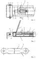
- deflection and Clamping device shown in the form of a plan view preferred embodiment of a deflection and Clamping device is within a C-shaped Guide rail 1 radially and along an axis M outlined longitudinal central axis axially displaceable.
- the slightly horseshoe-shaped deflection device 3 turns in Drive medium, i.e. a drive chain 2, tensioned by the Tensioning device so that the drive chain 2 within the guide rail 1 at the same distance from both Sides of the longitudinal central axis M is movable.
- Drive medium i.e. a drive chain 2
- the tensioning device has an axially lying compression spring 4 on the right end at one with the Guide rail 1 firmly connected as a stop 5 serving bracket and on the left of the deflection 3 supports and thereby the deflection device 3 in the axial, pressed by an arrow 6 indicated clamping direction.
- a Blind hole (not shown) in the deflection device 3 is used for receiving the compression spring 4.
- the stop 5 two tabs 15 and holes into which a screw bolt 14 is used with a nut 13, which is the actual Hold the wall or ceiling mounting profile.
- Fig. 2 which is shown in Fig. 1 as a plan view Deflection and tensioning device in a partially cut Side view shows that a bias lever 7th in a recess 10 (Fig. 1) between the stop 5 and the deflection device 3 engages.
- this pretension lever 7 which preferably the guide arm of the garage door operator is
- the deflection device 3 against the spring force press the compression spring 4 in the opposite direction to 6 and thereby release the tension of the tensioning device so that the drive medium, i.e. the Drive chain 2, tension-free around the deflection device 3 placed or removed from it. If in this state Drive chain 2 has been placed around the deflection device 3 is by relieving the lever 7 Drive chain 2 tensioned by the compression spring 4.
- Fig. 2 also shows that the deflection device 3 from one Deflection pin 11, which is about the wrap angle extending jacket area as a fixed, the drive chain immediately radially supporting slideway 12 is formed. Furthermore, the jacket area also has the surface elements for lateral guidance of the drive chain on.
- Fig. 3 shows a plan view of the as a biasing lever used guide arm 7 of the door operator.
- the guide arm has two recesses 8 and 9 which are in the in Fig. 1 shown recess 10 of the stop 5 engage.
- the interlocking of the recesses 8, 9 and 10 brings the clamping lever 7 in the correct position and prevented slipping at the same time.
Landscapes
- Power-Operated Mechanisms For Wings (AREA)
- Operating, Guiding And Securing Of Roll- Type Closing Members (AREA)
Abstract
Description
- Fig. 1 schematisch eine ebene Draufsicht auf eine bevorzugte Ausführungsform der erfindungsgemäßen Umlenk- und Spannvorrichtung,
- Fig. 2 die in Fig. 1 gezeigte Umlenk- und Spannvorrichtung gemäß der Erfindung in einer teilweise geschnittenen schematische Seitenansicht, und
- Fig. 3 in Draufsicht den erfindungsgemäß als Führungsarm dienenden Vorspannhebel.
Claims (7)
- Umlenk- und Spannvorrichtung für ein Antriebsmedium, insbesondere eine Antriebskette eines Garagentorantriebs, mit einer das in oder an einer Führungsschiene (1) bewegliche, gespannte Antriebsmedium (2) umlenkenden Umlenkvorrichtung,
dadurch gekennzeichnet, daßdie Umlenkvorrichtung (3) im Inneren der Führungsschiene (1) radial geführt und axial verschiebbar ist, unddie Spannvorrichtung eine Druckfeder (4) aufweist, die in axialer Richtung zwischen der beweglichen Umlenkvorrichtung (3) und einem in der Führungsschiene vorgesehenen und mit ihr fest verbundenen Anschlag (5) federnd eingreift und dadurch die Umlenkvorrichtung (3) in Spannrichtung (6) drückt. - Umlenk- und Spannvorrichtung nach Anspruch 1, dadurch gekennzeichnet, daß die Umlenkvorrichtung (3) von der in Form eines C-Profils ausgebildeten Führungsschiene (1) umgeben und darin mittig so eingesetzt und geführt ist, daß sie das umgelenkte Antriebsmedium (2) in jeweils gleichem Abstand beiderseits der Längsmittelachse (M) innerhalb der Führungsschiene (1) hält.
- Umlenk- und Spannvorrichtung nach Anspruch 1 oder 2, dadurch gekennzeichnet, daß weiterhin ein Vorspannhebel (7) zwischen dem Anschlag (5) und der Umlenkvorrichtung (3) so einbringbar ist, daß die Umlenkvorrichtung (3) durch die Betätigung des Vorspannhebels (7) gegen die Federkraft der Druckfeder (4) verschiebbar ist, wobei sich das Antriebsmedium (2) spannungsfrei um die Umlenkvorrichtung (3) legen oder davon abnehmen läßt.
- Umlenk- und Spannvorrichtung nach Anspruch 3, dadurch gekennzeichnet, daß der Vorspannhebel (7) der Führungsarm des Garagentorantriebs ist.
- Umlenk- und Spannvorrichtung nach Anspruch 4, dadurch gekennzeichnet, daß der Führungsarm (7) zwei Aussparungen (8, 9) hat, die in eine entsprechende Aussparung (10) des Haltewinkels eingreifen.
- Umlenk- und Spannvorrichtung nach einem der vorangehenden Ansprüche, dadurch gekennzeichnet, daß sie zum Spannen und Umlenken einer Antriebskette (2) eingerichtet ist.
- Umlenk- und Spannvorrichtung nach Anspruch 6, dadurch gekennzeichnet, daß die Umlenkvorrichtung einen Umlenkzapfen (11) aufweist, dessen sich über den Umschlingungswinkel erstreckender Mantelbereich als feststehende, die Antriebskette unmittelbar radial abstützende Gleitbahn (12) ausgebildet ist, wobei der Mantelbereich auch die zur seitlichen Führung der Antriebskette dienenden Flächenelemente aufweist.
Applications Claiming Priority (2)
| Application Number | Priority Date | Filing Date | Title |
|---|---|---|---|
| DE29802198U DE29802198U1 (de) | 1998-02-10 | 1998-02-10 | Umlenk- und Spannvorrichtung für die Antriebskette eines Garagentorantriebs |
| DE29802198U | 1998-02-10 |
Publications (2)
| Publication Number | Publication Date |
|---|---|
| EP0936337A1 true EP0936337A1 (de) | 1999-08-18 |
| EP0936337B1 EP0936337B1 (de) | 2003-05-28 |
Family
ID=8052413
Family Applications (1)
| Application Number | Title | Priority Date | Filing Date |
|---|---|---|---|
| EP99101260A Expired - Lifetime EP0936337B1 (de) | 1998-02-10 | 1999-01-23 | Umlenk- und Spannvorrichtung für die Antriebskette eines Garagentorantriebs |
Country Status (3)
| Country | Link |
|---|---|
| EP (1) | EP0936337B1 (de) |
| AT (1) | ATE241750T1 (de) |
| DE (2) | DE29802198U1 (de) |
Cited By (1)
| Publication number | Priority date | Publication date | Assignee | Title |
|---|---|---|---|---|
| DE10002606A1 (de) * | 1999-11-24 | 2001-09-06 | Hoermann Kg Antriebstechnik | Antriebsvorrichtung sowie darin verwendbare Zugmittelspannvorrichtung |
Citations (4)
| Publication number | Priority date | Publication date | Assignee | Title |
|---|---|---|---|---|
| GB949353A (en) * | 1961-03-13 | 1964-02-12 | Berry Door Corp | Improvements relating to operating mechanisms for doors |
| DE4342380A1 (de) | 1993-01-14 | 1994-07-21 | Bosch Gmbh Robert | Umlenkvorrichtung für Antriebsketten, insbesondere von Garagentorantrieben |
| EP0732476A1 (de) * | 1995-03-17 | 1996-09-18 | Hörmann KG Verkaufsgesellschaft | Antriebseinrichtung |
| EP0743416A1 (de) * | 1995-05-19 | 1996-11-20 | Hörmann KG Verkaufsgesellschaft | Antriebseinrichtung für ein Torblatt |
-
1998
- 1998-02-10 DE DE29802198U patent/DE29802198U1/de not_active Expired - Lifetime
-
1999
- 1999-01-23 EP EP99101260A patent/EP0936337B1/de not_active Expired - Lifetime
- 1999-01-23 DE DE59905689T patent/DE59905689D1/de not_active Expired - Lifetime
- 1999-01-23 AT AT99101260T patent/ATE241750T1/de not_active IP Right Cessation
Patent Citations (4)
| Publication number | Priority date | Publication date | Assignee | Title |
|---|---|---|---|---|
| GB949353A (en) * | 1961-03-13 | 1964-02-12 | Berry Door Corp | Improvements relating to operating mechanisms for doors |
| DE4342380A1 (de) | 1993-01-14 | 1994-07-21 | Bosch Gmbh Robert | Umlenkvorrichtung für Antriebsketten, insbesondere von Garagentorantrieben |
| EP0732476A1 (de) * | 1995-03-17 | 1996-09-18 | Hörmann KG Verkaufsgesellschaft | Antriebseinrichtung |
| EP0743416A1 (de) * | 1995-05-19 | 1996-11-20 | Hörmann KG Verkaufsgesellschaft | Antriebseinrichtung für ein Torblatt |
Cited By (2)
| Publication number | Priority date | Publication date | Assignee | Title |
|---|---|---|---|---|
| DE10002606A1 (de) * | 1999-11-24 | 2001-09-06 | Hoermann Kg Antriebstechnik | Antriebsvorrichtung sowie darin verwendbare Zugmittelspannvorrichtung |
| DE10002606B4 (de) * | 1999-11-24 | 2008-05-15 | Hörmann KG Antriebstechnik | Torantrieb mit Zugmittelgetriebe und Zugmittelspannvorrichtung |
Also Published As
| Publication number | Publication date |
|---|---|
| DE29802198U1 (de) | 1999-06-10 |
| DE59905689D1 (de) | 2003-07-03 |
| ATE241750T1 (de) | 2003-06-15 |
| EP0936337B1 (de) | 2003-05-28 |
Similar Documents
| Publication | Publication Date | Title |
|---|---|---|
| DE19619087C2 (de) | Befestigungsvorrichtung | |
| DE102007013446B4 (de) | Elektrisches Stellglied | |
| DE2750904A1 (de) | Fensterheber, insbesondere fuer kraftfahrzeuge | |
| EP3623688B1 (de) | Abdeckvorrichtung | |
| DE19615589A1 (de) | Kabelspannvorrichtung | |
| EP0732243B1 (de) | Vorrichtung zur Betätigung einer Feststellbremse | |
| EP0172351A1 (de) | Fanggerät | |
| DE4024666C2 (de) | Sektionaltor | |
| DE4340410C2 (de) | Oberflächenentwässerungseinrichtung | |
| DE10030985A1 (de) | Leitungsführungseinrichtung | |
| DE19914860B4 (de) | Einrichtung zur Führung und Wegbegrenzung eines Schiebetürelements | |
| DE102019103917A1 (de) | Greif- oder Spannvorrichtung mit einer Brems und/oder Festsetzeinheit | |
| DD269586B3 (de) | Einrichtung zum lagegenauen schnellaufspannen von flexiblen druckplatten | |
| DE68917780T2 (de) | Automatische Spannvorrichtung für ein in einer biegsamen Hülle geführtes Zugkabel. | |
| EP2995502B1 (de) | Dachträgeranordnung für ein kraftfahrzeug | |
| EP0936337A1 (de) | Umlenk- und Spannvorrichtung für die Antriebskette eines Garagentorantriebs | |
| DE2406906A1 (de) | Tuerfeststeller, insbesondere fuer kraftfahrzeuge | |
| EP4078638B1 (de) | Not-halt-schalter und maschine mit not-halt-schalter | |
| EP1196679B1 (de) | Vorrichtung zur führung von maschinenelementen | |
| DE19719324C2 (de) | Feststellvorrichtung | |
| DE3007653A1 (de) | Seilfensterheber | |
| DE102024109750B3 (de) | Anordnung aus einer Baugruppe für ein Kraftfahrzeug und mindestens einem Seilzug-Antrieb, sowie Kraftahrzeug | |
| DE2917023B2 (de) | Seilzug mit Toraufhänger und darin eingebauter Schlaffseilsicherung für ein Deckenglieder- oder Rolltor | |
| EP1353121B1 (de) | Triangelaufhängung für Hängeleuchten | |
| DE20110546U1 (de) | Garagentor |
Legal Events
| Date | Code | Title | Description |
|---|---|---|---|
| PUAI | Public reference made under article 153(3) epc to a published international application that has entered the european phase |
Free format text: ORIGINAL CODE: 0009012 |
|
| AK | Designated contracting states |
Kind code of ref document: A1 Designated state(s): AT CH DE ES GB IT LI |
|
| AX | Request for extension of the european patent |
Free format text: AL;LT;LV;MK;RO;SI |
|
| 17P | Request for examination filed |
Effective date: 20000218 |
|
| AKX | Designation fees paid |
Free format text: AT CH DE ES GB IT LI |
|
| 17Q | First examination report despatched |
Effective date: 20000623 |
|
| RAP1 | Party data changed (applicant data changed or rights of an application transferred) |
Owner name: SOMFY FEINMECHANIK UND ELEKTROTECHNIK GMBH |
|
| GRAH | Despatch of communication of intention to grant a patent |
Free format text: ORIGINAL CODE: EPIDOS IGRA |
|
| GRAH | Despatch of communication of intention to grant a patent |
Free format text: ORIGINAL CODE: EPIDOS IGRA |
|
| GRAA | (expected) grant |
Free format text: ORIGINAL CODE: 0009210 |
|
| AK | Designated contracting states |
Designated state(s): AT CH DE ES GB IT LI |
|
| PG25 | Lapsed in a contracting state [announced via postgrant information from national office to epo] |
Ref country code: IT Free format text: LAPSE BECAUSE OF FAILURE TO SUBMIT A TRANSLATION OF THE DESCRIPTION OR TO PAY THE FEE WITHIN THE PRESCRIBED TIME-LIMIT;WARNING: LAPSES OF ITALIAN PATENTS WITH EFFECTIVE DATE BEFORE 2007 MAY HAVE OCCURRED AT ANY TIME BEFORE 2007. THE CORRECT EFFECTIVE DATE MAY BE DIFFERENT FROM THE ONE RECORDED. Effective date: 20030528 Ref country code: GB Free format text: LAPSE BECAUSE OF FAILURE TO SUBMIT A TRANSLATION OF THE DESCRIPTION OR TO PAY THE FEE WITHIN THE PRESCRIBED TIME-LIMIT Effective date: 20030528 |
|
| REG | Reference to a national code |
Ref country code: GB Ref legal event code: FG4D Free format text: NOT ENGLISH |
|
| REG | Reference to a national code |
Ref country code: CH Ref legal event code: EP |
|
| REF | Corresponds to: |
Ref document number: 59905689 Country of ref document: DE Date of ref document: 20030703 Kind code of ref document: P |
|
| PG25 | Lapsed in a contracting state [announced via postgrant information from national office to epo] |
Ref country code: ES Free format text: LAPSE BECAUSE OF FAILURE TO SUBMIT A TRANSLATION OF THE DESCRIPTION OR TO PAY THE FEE WITHIN THE PRESCRIBED TIME-LIMIT Effective date: 20030908 |
|
| GBV | Gb: ep patent (uk) treated as always having been void in accordance with gb section 77(7)/1977 [no translation filed] |
Effective date: 20030528 |
|
| PG25 | Lapsed in a contracting state [announced via postgrant information from national office to epo] |
Ref country code: AT Free format text: LAPSE BECAUSE OF NON-PAYMENT OF DUE FEES Effective date: 20040123 |
|
| PG25 | Lapsed in a contracting state [announced via postgrant information from national office to epo] |
Ref country code: LI Free format text: LAPSE BECAUSE OF NON-PAYMENT OF DUE FEES Effective date: 20040131 Ref country code: CH Free format text: LAPSE BECAUSE OF NON-PAYMENT OF DUE FEES Effective date: 20040131 |
|
| PLBE | No opposition filed within time limit |
Free format text: ORIGINAL CODE: 0009261 |
|
| STAA | Information on the status of an ep patent application or granted ep patent |
Free format text: STATUS: NO OPPOSITION FILED WITHIN TIME LIMIT |
|
| 26N | No opposition filed |
Effective date: 20040302 |
|
| REG | Reference to a national code |
Ref country code: CH Ref legal event code: PL |
|
| PGFP | Annual fee paid to national office [announced via postgrant information from national office to epo] |
Ref country code: DE Payment date: 20110115 Year of fee payment: 13 |
|
| PG25 | Lapsed in a contracting state [announced via postgrant information from national office to epo] |
Ref country code: DE Free format text: LAPSE BECAUSE OF NON-PAYMENT OF DUE FEES Effective date: 20120801 |
|
| REG | Reference to a national code |
Ref country code: DE Ref legal event code: R119 Ref document number: 59905689 Country of ref document: DE Effective date: 20120801 |