EP0936360B1 - Dispositif d'assemblage, en particulier pour éléments tubulaires - Google Patents
Dispositif d'assemblage, en particulier pour éléments tubulaires Download PDFInfo
- Publication number
- EP0936360B1 EP0936360B1 EP19990440025 EP99440025A EP0936360B1 EP 0936360 B1 EP0936360 B1 EP 0936360B1 EP 19990440025 EP19990440025 EP 19990440025 EP 99440025 A EP99440025 A EP 99440025A EP 0936360 B1 EP0936360 B1 EP 0936360B1
- Authority
- EP
- European Patent Office
- Prior art keywords
- mounting part
- post
- bar
- assembly
- assembly device
- Prior art date
- Legal status (The legal status is an assumption and is not a legal conclusion. Google has not performed a legal analysis and makes no representation as to the accuracy of the status listed.)
- Expired - Lifetime
Links
- 229920001971 elastomer Polymers 0.000 claims description 2
- 239000000806 elastomer Substances 0.000 claims description 2
- 230000000149 penetrating effect Effects 0.000 claims description 2
- 238000007373 indentation Methods 0.000 claims 2
- 230000001747 exhibiting effect Effects 0.000 claims 1
- 239000000470 constituent Substances 0.000 description 2
- 238000004519 manufacturing process Methods 0.000 description 2
- 230000000712 assembly Effects 0.000 description 1
- 238000000429 assembly Methods 0.000 description 1
- 230000000903 blocking effect Effects 0.000 description 1
- 230000004048 modification Effects 0.000 description 1
- 238000012986 modification Methods 0.000 description 1
- 230000003071 parasitic effect Effects 0.000 description 1
- 238000010079 rubber tapping Methods 0.000 description 1
- 238000000926 separation method Methods 0.000 description 1
- 238000006467 substitution reaction Methods 0.000 description 1
Images

Classifications
-
- E—FIXED CONSTRUCTIONS
- E04—BUILDING
- E04F—FINISHING WORK ON BUILDINGS, e.g. STAIRS, FLOORS
- E04F11/00—Stairways, ramps, or like structures; Balustrades; Handrails
- E04F11/18—Balustrades; Handrails
- E04F11/181—Balustrades
- E04F11/1817—Connections therefor
-
- F—MECHANICAL ENGINEERING; LIGHTING; HEATING; WEAPONS; BLASTING
- F16—ENGINEERING ELEMENTS AND UNITS; GENERAL MEASURES FOR PRODUCING AND MAINTAINING EFFECTIVE FUNCTIONING OF MACHINES OR INSTALLATIONS; THERMAL INSULATION IN GENERAL
- F16B—DEVICES FOR FASTENING OR SECURING CONSTRUCTIONAL ELEMENTS OR MACHINE PARTS TOGETHER, e.g. NAILS, BOLTS, CIRCLIPS, CLAMPS, CLIPS OR WEDGES; JOINTS OR JOINTING
- F16B7/00—Connections of rods or tubes, e.g. of non-circular section, mutually, including resilient connections
- F16B7/04—Clamping or clipping connections
- F16B7/044—Clamping or clipping connections for rods or tubes being in angled relationship
- F16B7/0446—Clamping or clipping connections for rods or tubes being in angled relationship for tubes using the innerside thereof
- F16B7/0453—Clamping or clipping connections for rods or tubes being in angled relationship for tubes using the innerside thereof the tubes being drawn towards each other
Definitions
- the present invention relates to the field of manufacture industrial manufacture of ironwork, in particular for railings, railings and analogous, and relates to an assembly device, in particular for elements guard rail trough or the like.
- connection means are generally in the form of rigid tee connections, in the case of mounting smooth or under-slats, or in the form of a set of parts hinged together means of a locking pin in the service position, one of the parts being inserted in the end of the pole or bar and forming the pivot of the other piece of receiving and supporting the constituent tube of the stair rail or the like, the fixing the pivot piece in the corresponding end of the bar or pole and the fixing of the tube forming a stair rail or the like being made by means of countersunk screws.
- the devices existing ones are of a relatively high cost price.
- the aesthetic appearance of the devices obtained is relatively questionable, the hinge element necessarily forming a harmful interruption from this point of view.
- the very presence of a articulation requires a suitable tightening after setting up the different elements, to avoid any parasitic play.
- a device assembly for hollow railing elements or the like which is essentially constituted by a mounting piece in the end of a pole or a bar fixed in said post or bar and by a support piece provided with a cradle for receiving a tubular element forming a smooth, sub-smooth, ramp or the like, the two parts being interconnected by means of a ball joint which can be locked in position, after adjustment, by via at least one connecting means.
- This embodiment allows obtaining an assembly that can be entirely prefabricated and favoring a quick assembly with relatively low tooling costs.
- this assembly device requires, for final tightening of the mounting piece on the support piece, a disassembly of the ramp or smooth after adjusting the position of the latter, in order to access the assembly means.
- document GB-A-2 149 047 describes a device of assembly between two elements of cylindrical section implementing a Stud tightened in a blind hole by means of a set screw. This document only describes perfectly predetermined assemblies not allowing no angular adjustment of the alignment type of two pieces in extension or two-piece mounting with the possibility of adjustable angular offset.
- this document does not disclose any device of assembly allowing a position adjustment of the parts to be assembled before their permanent locking in position, without requiring disassembly before blocking the set position, then a reassembly of the elements to be mounted between them.
- the present invention aims to overcome the disadvantages of assembly devices known to date by proposing an assembly device, in particular for hollow elements of guardrails or the like, allowing perform quick and easy assembly, adjustment and locking of its parts constituent.
- the device according to the invention is characterized in that that it basically consists of a mounting piece in the end of a post or bar, a rail, a sub-rail, a rail or the like, fixed in said post or bar, and by a connecting means of this piece of mounting with the corresponding end of a corresponding mounting piece or with a tubular element forming a smooth, sub-smooth, ramp or post or analogous, said mounting piece and the connecting means being connected to one another way of a hinge that can be locked in position, after adjustment, by via at least one connecting means.
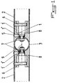
- the assembly device in particular for hollow guardrail elements or analogous, essentially consists of a mounting piece 1 in the end of a pole or of a bar 2, a rail, a sub-rail, a rail ramp or the like, fixed in said post or bar 2 and by means 3 of connection of this mounting piece 1 with the corresponding end of a piece of corresponding assembly 1 (FIG. 1) or with a tubular element 4 forming post or the like (FIG. 2), said mounting piece 1 and the connecting means 3 being interconnected in the manner of a hinge that can be locked into position, after adjustment, via at least one connecting means 5.
- the mounting piece 1 in the end of a post or bar 2 of a rail, a sub-rail, a ramp or the like is advantageously constituted in the form of an element presenting an end 1 'snag in the corresponding end of said pole or bar 2 with abutment against said end of the latter by via a shoulder 1 ", the holding of said mounting piece 1 in the post or bar 2 being provided by a connecting means 6 passing through the wall of the post or bar 2 and tight in the end emmanchable 1 'of the room of Mounting 1.
- the emmanchable end 1 'of the mounting piece 1 has two diametrically opposite parts, one of which is crossed by the medium bond 6 passing through the wall of the post or bar 2 and the other form a bearing surface for the end of said connecting means 6.
- the latter is preferably constituted by a grub screw through a hole of corresponding section of the wall of the post or bar 2 and cooperating with a corresponding tapping of a part of the end 1 'of the mounting part 1, the length of this screw being such that it is completely drowned on the external surface of the post or bar 2 in service position.
- the means 3 for connecting the mounting piece 1 with the end corresponding part of a corresponding mounting part 1 ( Figure 1) is advantageously constituted, according to a first embodiment of the invention, by a spherical element provided with at least two through bolts 7, whose head screw is advantageously conical, each screw head penetrating into a bore 8 of corresponding section of the corresponding mounting piece 1, the end corresponding free movement of the mounting piece 1 having a concave shape hemisphere corresponding to that of the means 3.
- at least one of the through holes of the screws forming the bolts 7 is an oblong hole 9.
- the means 3 of connecting the workpiece 1 with the end corresponding part of a corresponding mounting part 1 in the form of an element tubular having at least two through-holes for bolts forming bolts 7, one of these holes being advantageously oblong, these holes being able to be in a same plane or in different planes, the corresponding free end of the mounting piece 1 having a corresponding semi-cylindrical concave shape to that of the means 3.
- Such an embodiment allows the implementation of tubular elements forming bars receiving posts, smooth or analogous, said bars, smooth or the like, connectable to said poles at different levels, for example for a level change from one litter to another.
- Figure 2 of the accompanying drawings represents another variant of embodiment of the invention, in which the means 3 for connecting a piece of assembly 1 with a tubular element 4 forming a pole or the like is presented in the form of a female-female connecting element, one of whose ends is provided with a hemispherical recess 10 which can cooperate with one end corresponding hemispherical part of a mounting piece 1 and whose other end is provided with a semi-cylindrical imprint 11 for cooperation with a cylindrical post 4 or the like, the axis of the semi-cylindrical imprint 11 being advantageously located in a plane secant from that of the recess hemispherical 10, different from 90 ° and the bolt 7 assembly being mounted on the end of the mounting piece 1.
- the end hemispherical part of the mounting part 1 is advantageously provided with a hole oblong passage of the screw forming the bolt 7 assembly with the means of connection 3, the attachment of the latter on the tubular element 4 forming a pole or analogous being achieved by means of a screw 12 or the like housed in the body of the connecting means 3 and cooperating with an anchor or the like provided in the post 4.
- the means 5 for assembling and locking in position, after adjustment, of the mounting part 1 and the connecting means 3 is advantageously constituted by at least one conical end pressure screw, said end of which bears under the face tapered head of the screw forming the bolt 7 assembly.
- a gap between the screw head forming the bolt 7 assembly and the spherical or cylindrical bearing on which is mounted said bolt 7 is provided by providing a ring 13 of elastomer or the like between said head and said span spherical or cylindrical.
- the invention it is possible to produce an assembly, particular of decorative hollow elements, in the field of ironwork, particularly used for obtaining railings, balustrades or others, whose individual components can be mounted separately on the respective tubes, while being able to be positioned easily.
Landscapes
- Engineering & Computer Science (AREA)
- Architecture (AREA)
- General Engineering & Computer Science (AREA)
- Civil Engineering (AREA)
- Structural Engineering (AREA)
- Mechanical Engineering (AREA)
- Bridges Or Land Bridges (AREA)
- Refuge Islands, Traffic Blockers, Or Guard Fence (AREA)
- Steps, Ramps, And Handrails (AREA)
Description
Claims (12)
- Dispositif d'assemblage, en particulier pour éléments creux de garde-corps ou analogue, caractérisé en ce qu'il est essentiellement constitué par une pièce (1) de montage dans l'extrémité d'un poteau ou d'un barreau (2), d'une lisse, d'une sous-lisse, d'une rampe ou analogue, fixée dans ledit poteau ou barreau (2) et par un moyen (3) de liaison de cette pièce de montage (1) avec l'extrémité correspondante d'une pièce de montage (1) correspondante ou avec un élément tubulaire (4) formant poteau ou analogue, la pièce (1) de montage et le moyen (3) de liaison étant assemblés séparément audit poteau, barreau (2), lisse, sous-lisse, rampe ou analogue ou à l'élément tubulaire (4) formant poteau ou analogue et étant reliés entre-eux à la manière d'une articulation pouvant être bloquée en position, après réglage, par l'intermédiaire d'au moins un moyen d'assemblage (5), sans démontage, avant blocage, des éléments assemblés à la pièce (1) de montage et au moyen (3) de liaison.
- Dispositif d'assemblage, suivant la revendication 1, caractérisé en ce que la pièce (1) de montage dans l'extrémité d'un poteau ou d'un barreau (2) d'une lisse, d'une sous-lisse, d'une rampe ou analogue, est constituée sous forme d'un élément présentant une extrémité (1') emmanchable dans l'extrémité correspondante dudit poteau ou barreau (2) avec mise en butée contre ladite extrémité de ce dernier par l'intermédiaire d'un épaulement (1"), le maintien de ladite pièce de montage (1) dans le poteau ou barreau (2) étant assuré par un moyen de liaison (6) traversant la paroi du poteau ou barreau (2) et serré dans l'extrémité emmanchable (1') de la pièce de montage (1).
- Dispositif d'assemblage, suivant la revendication 2, caractérisé en ce que l'extrémité emmanchable (1') de la pièce de montage (1) présente deux parties diamétralement opposées, dont l'une est traversée par le moyen liaison (6) traversant la paroi du poteau ou barreau (2) et dont l'autre forme une surface d'appui pour l'extrémité dudit moyen liaison (6).
- Dispositif d'assemblage, suivant l'une quelconque des revendications 1 et 2 ou 3, caractérisé en ce que le moyen liaison (6) est constitué par une vis sans tête traversant un trou de section correspondante de la paroi du poteau ou barreau (2) et coopérant avec un taraudage correspondant d'une partie de l'extrémité emmanchable (1') de la pièce de montage (1), la longueur de cette vis étant telle qu'elle soit complètement noyée à la surface externe du poteau ou barreau (2) en position de service.
- Dispositif d'assemblage, suivant la revendication 1, caractérisé en ce que le moyen (3) de liaison de la pièce de montage (1) avec l'extrémité correspondante d'une pièce de montage (1) correspondante est constitué par un élément sphérique muni d'au moins deux boulons traversants (7), dont la tête de vis est avantageusement conique, chaque tête de vis pénétrant dans un perçage (8) de section correspondante de la pièce de montage (1) correspondante, l'extrémité libre correspondante de la pièce de montage (1) présentant une forme concave hémisphérique correspondant à celle du moyen (3).
- Dispositif d'assemblage, suivant les revendications 1 et 5, caractérisé en ce qu'au moins l'un des trous de traversée des vis formant les boulons (7) est un trou oblong (9).
- Dispositif d'assemblage, suivant les revendications 1 et 5, caractérisé en ce que le moyen (3) de liaison de la pièce 1 avec l'extrémité correspondante d'une pièce de montage (1) correspondante est sous forme d'un élément tubulaire muni d'au moins deux trous de passage pour les vis formant les boulons (7), l'un de ces trous étant oblong, ces trous pouvant être dans un même plan ou dans des plans différents, l'extrémité libre correspondante de la pièce de montage (1) présentant une forme concave semi-cylindrique correspondant à celle du moyen (3).
- Dispositif d'assemblage, suivant les revendications 1 et 5, caractérisé en ce que le moyen (3) de liaison d'une pièce de montage (1) avec un élément tubulaire (4) formant poteau ou analogue se présente sous forme d'un élément de liaison femelle-femelle, dont l'une des extrémités est munie d'un évidement hémisphérique (10) pouvant coopérer avec une extrémité hémisphérique correspondante d'une pièce de montage (1) et dont l'autre extrémité est pourvue d'une empreinte semi-cylindrique (11) permettant la coopération avec un poteau cylindrique (4) ou analogue, l'axe de l'empreinte semi-cylindrique (11) étant avantageusement situé dans un plan sécant de celui de l'évidement hémisphérique (10), différent de 90° et le boulon (7) d'assemblage étant monté sur l'extrémité de la pièce de montage (1).
- Dispositif d'assemblage, suivant la revendication 8, caractérisé en ce que l'extrémité hémisphérique de la pièce de montage (1) est muni d'un trou oblong de passage de la vis formant le boulon (7) d'assemblage avec le moyen de liaison (3), la fixation de ce dernier sur l'élément tubulaire (4) formant poteau ou analogue étant réalisée par l'intermédiaire d'une vis (12) ou analogue, logée dans le corps du moyen de liaison (3) et coopérant avec une cheville ou analogue prévue dans le poteau (4).
- Dispositif d'assemblage, suivant l'une quelconque des revendications 1 et 5 à 9, caractérisé en ce que le moyen (5) d'assemblage et de blocage en position, après réglage, de la pièce de montage (1) et du moyen de liaison (3), est constitué par au moins une vis de pression à bout conique, dont ledit bout s'appuie sous la face conique de la tête de la vis formant le boulon (7) d'assemblage.
- Dispositif d'assemblage, suivant l'une quelconque des revendications 1 et 5 à 10, caractérisé en ce qu'un écartement entre la tête de vis formant le boulon (7) d'assemblage et la portée sphérique ou cylindrique sur laquelle est monté ledit boulon (7) est assuré par prévision d'un anneau (13) en élastomère ou autre entre ladite tête et ladite portée sphérique ou cylindrique.
- Dispositif d'assemblage, suivant la revendication 1, caractérisé en ce que les différentes liaisons sont du type à surfaces planes par coopération de formes angulaires.
Applications Claiming Priority (2)
| Application Number | Priority Date | Filing Date | Title |
|---|---|---|---|
| FR9801803 | 1998-02-11 | ||
| FR9801803A FR2774714B1 (fr) | 1998-02-11 | 1998-02-11 | Dispositif d'assemblage, en particulier pour elements creux de garde-corps ou analogue |
Publications (3)
| Publication Number | Publication Date |
|---|---|
| EP0936360A2 EP0936360A2 (fr) | 1999-08-18 |
| EP0936360A3 EP0936360A3 (fr) | 2001-11-07 |
| EP0936360B1 true EP0936360B1 (fr) | 2005-10-05 |
Family
ID=9522985
Family Applications (1)
| Application Number | Title | Priority Date | Filing Date |
|---|---|---|---|
| EP19990440025 Expired - Lifetime EP0936360B1 (fr) | 1998-02-11 | 1999-02-05 | Dispositif d'assemblage, en particulier pour éléments tubulaires |
Country Status (4)
| Country | Link |
|---|---|
| EP (1) | EP0936360B1 (fr) |
| DE (1) | DE69927538T2 (fr) |
| ES (1) | ES2249876T3 (fr) |
| FR (1) | FR2774714B1 (fr) |
Families Citing this family (5)
| Publication number | Priority date | Publication date | Assignee | Title |
|---|---|---|---|---|
| DE20100893U1 (de) * | 2001-01-17 | 2001-06-28 | Julius Cronenberg offene Handelsgesellschaft, 59757 Arnsberg | Einrichtung für die Befestigung einer Geländerstrebe an einem Pfosten |
| DE20203656U1 (de) * | 2002-03-06 | 2003-07-17 | Leitner GmbH, 71332 Waiblingen | Verbindungsanordnung |
| DE20313143U1 (de) * | 2003-08-22 | 2004-12-30 | Rixen, Wolfgang, Dipl.-Ing. | Verbindungselement |
| FR2963395B1 (fr) * | 2010-07-27 | 2014-02-21 | Proinoxasi | Ensemble d'elements emboitables destine notamment a former un garde-corps, une balustrade, une rampe ou un conduit de fluide |
| CN108569179B (zh) * | 2017-03-14 | 2021-05-14 | 湖南中车时代电动汽车股份有限公司 | 一种车载扶手杆连接配件及扶手杆装配方法 |
Family Cites Families (5)
| Publication number | Priority date | Publication date | Assignee | Title |
|---|---|---|---|---|
| US4150907A (en) * | 1978-03-08 | 1979-04-24 | Julius Blum & Co., Inc. | Stanchion connector assembly |
| GB2149047B (en) * | 1983-10-29 | 1988-04-13 | Brian Laurance Wright | Connecting arrangement |
| US4867596A (en) * | 1988-08-04 | 1989-09-19 | Morton Ocuin | Connector for elongate elements |
| DE4336282A1 (de) * | 1993-10-25 | 1995-04-27 | Kreusel Magda | Verbindungselement für zwei sich kreuzende Rohre |
| FR2713723B1 (fr) | 1993-12-10 | 1996-01-12 | Schutt Ferronniers Art Sa | Dispositif d'assemblage, en particulier pour éléments creux de garde-corps ou analogue. |
-
1998
- 1998-02-11 FR FR9801803A patent/FR2774714B1/fr not_active Expired - Fee Related
-
1999
- 1999-02-05 DE DE69927538T patent/DE69927538T2/de not_active Expired - Lifetime
- 1999-02-05 EP EP19990440025 patent/EP0936360B1/fr not_active Expired - Lifetime
- 1999-02-05 ES ES99440025T patent/ES2249876T3/es not_active Expired - Lifetime
Also Published As
| Publication number | Publication date |
|---|---|
| DE69927538D1 (de) | 2006-02-16 |
| DE69927538T2 (de) | 2006-07-06 |
| FR2774714B1 (fr) | 2000-04-14 |
| EP0936360A2 (fr) | 1999-08-18 |
| ES2249876T3 (es) | 2006-04-01 |
| FR2774714A1 (fr) | 1999-08-13 |
| EP0936360A3 (fr) | 2001-11-07 |
Similar Documents
| Publication | Publication Date | Title |
|---|---|---|
| EP0964107B1 (fr) | Noeud d'assemblage | |
| CA2239933C (fr) | Dispositif de jonction pour main courante | |
| EP0558731A1 (fr) | Dispositif d'aide a la marche, de type bequille ou canne anglaise | |
| EP2003265B1 (fr) | Système de balustrade, rampe ou analogue | |
| FR2668800A2 (fr) | Dispositif de liaison pour reunir bout a bout deux barres. | |
| EP0936360A2 (fr) | Dispositif d'assemblage, en particulier pour éléments tubulaires | |
| FR2868136A1 (fr) | Vis pour accrocher un profile creux en matiere plastique renforce par un profile metallique a une infrastructure | |
| WO2021004756A1 (fr) | Dispositif pour positionner une fixation dans un perçage | |
| FR2915500A1 (fr) | Garde-corps. | |
| FR2468018A1 (fr) | Element d'assemblage extensible pour elements tubulaires | |
| US4643607A (en) | Furniture construction | |
| FR2713723A1 (fr) | Dispositif d'assemblage, en particulier pour éléments creux de garde-corps ou analogue. | |
| FR2519052A1 (fr) | Balustrade en elements prefabriques reglables pour la protection et la delimitation de surfaces planes et inclinees | |
| EP0651110B1 (fr) | Dispositif d'immobilisation d'un raidisseur vertical pour garde-corps vis-a-vis d'un support d'appui au sol | |
| FR2757891A1 (fr) | Dispositif d'assemblage de profiles de structure notamment pour toiture de veranda ou analogue | |
| EP0462039A1 (fr) | Dispositif de jeu modulaire | |
| EP0965766A1 (fr) | Dispositif d'assemblage pour pièces planes et éléments tubulaires | |
| FR2978780A1 (fr) | Dispositif de raccordement d'elements tubulaires et systeme l'integrant | |
| EP1072738B1 (fr) | Collier d'assemblage, en particulier pour mobilier urbain | |
| FR2690185A1 (fr) | Dispositif de fixation pour garde-corps. | |
| FR2711701A1 (fr) | Dispositif pour l'assemblage de barreaux avec une lisse de garde-corps. | |
| FR2819861A1 (fr) | Dispositif pour fixer en bout une barre sur un support | |
| EP1318251A1 (fr) | Articulation de sécurité notamment pour les rambardes d'échafaudage | |
| FR2864181A1 (fr) | Collier d'assemblage | |
| FR2612543A1 (fr) | Piece de raccordement d'angle pour lisse superieure et lisse intermediaire de garde-corps |
Legal Events
| Date | Code | Title | Description |
|---|---|---|---|
| PUAI | Public reference made under article 153(3) epc to a published international application that has entered the european phase |
Free format text: ORIGINAL CODE: 0009012 |
|
| AK | Designated contracting states |
Kind code of ref document: A2 Designated state(s): AT BE CH CY DE DK ES FI FR GB GR IE IT LI LU MC NL PT SE Kind code of ref document: A2 Designated state(s): BE DE ES FR GB IT NL |
|
| AX | Request for extension of the european patent |
Free format text: AL;LT;LV;MK;RO;SI |
|
| PUAL | Search report despatched |
Free format text: ORIGINAL CODE: 0009013 |
|
| AK | Designated contracting states |
Kind code of ref document: A3 Designated state(s): AT BE CH CY DE DK ES FI FR GB GR IE IT LI LU MC NL PT SE |
|
| AX | Request for extension of the european patent |
Free format text: AL;LT;LV;MK;RO;SI |
|
| RIC1 | Information provided on ipc code assigned before grant |
Free format text: 7E 04F 11/18 A, 7F 16B 7/04 B |
|
| 17P | Request for examination filed |
Effective date: 20011221 |
|
| AKX | Designation fees paid |
Free format text: BE DE ES FR GB IT NL |
|
| 17Q | First examination report despatched |
Effective date: 20041227 |
|
| GRAP | Despatch of communication of intention to grant a patent |
Free format text: ORIGINAL CODE: EPIDOSNIGR1 |
|
| GRAS | Grant fee paid |
Free format text: ORIGINAL CODE: EPIDOSNIGR3 |
|
| GRAA | (expected) grant |
Free format text: ORIGINAL CODE: 0009210 |
|
| AK | Designated contracting states |
Kind code of ref document: B1 Designated state(s): BE DE ES FR GB IT NL |
|
| REG | Reference to a national code |
Ref country code: GB Ref legal event code: FG4D Free format text: NOT ENGLISH |
|
| GBT | Gb: translation of ep patent filed (gb section 77(6)(a)/1977) | ||
| REF | Corresponds to: |
Ref document number: 69927538 Country of ref document: DE Date of ref document: 20060216 Kind code of ref document: P |
|
| PGFP | Annual fee paid to national office [announced via postgrant information from national office to epo] |
Ref country code: IT Payment date: 20060228 Year of fee payment: 8 |
|
| REG | Reference to a national code |
Ref country code: ES Ref legal event code: FG2A Ref document number: 2249876 Country of ref document: ES Kind code of ref document: T3 |
|
| PLBE | No opposition filed within time limit |
Free format text: ORIGINAL CODE: 0009261 |
|
| STAA | Information on the status of an ep patent application or granted ep patent |
Free format text: STATUS: NO OPPOSITION FILED WITHIN TIME LIMIT |
|
| 26N | No opposition filed |
Effective date: 20060706 |
|
| PG25 | Lapsed in a contracting state [announced via postgrant information from national office to epo] |
Ref country code: IT Free format text: LAPSE BECAUSE OF NON-PAYMENT OF DUE FEES Effective date: 20070205 |
|
| PGFP | Annual fee paid to national office [announced via postgrant information from national office to epo] |
Ref country code: ES Payment date: 20091230 Year of fee payment: 12 |
|
| PGFP | Annual fee paid to national office [announced via postgrant information from national office to epo] |
Ref country code: FR Payment date: 20100112 Year of fee payment: 12 |
|
| PGFP | Annual fee paid to national office [announced via postgrant information from national office to epo] |
Ref country code: GB Payment date: 20100224 Year of fee payment: 12 Ref country code: DE Payment date: 20100302 Year of fee payment: 12 Ref country code: BE Payment date: 20100129 Year of fee payment: 12 |
|
| PGFP | Annual fee paid to national office [announced via postgrant information from national office to epo] |
Ref country code: NL Payment date: 20100215 Year of fee payment: 12 |
|
| BERE | Be: lapsed |
Owner name: S.A. *GRANDE FORGE MANAGEMENT Effective date: 20110228 |
|
| REG | Reference to a national code |
Ref country code: NL Ref legal event code: V1 Effective date: 20110901 |
|
| GBPC | Gb: european patent ceased through non-payment of renewal fee |
Effective date: 20110205 |
|
| REG | Reference to a national code |
Ref country code: FR Ref legal event code: ST Effective date: 20111102 |
|
| PG25 | Lapsed in a contracting state [announced via postgrant information from national office to epo] |
Ref country code: BE Free format text: LAPSE BECAUSE OF NON-PAYMENT OF DUE FEES Effective date: 20110228 |
|
| PG25 | Lapsed in a contracting state [announced via postgrant information from national office to epo] |
Ref country code: NL Free format text: LAPSE BECAUSE OF NON-PAYMENT OF DUE FEES Effective date: 20110901 |
|
| REG | Reference to a national code |
Ref country code: DE Ref legal event code: R119 Ref document number: 69927538 Country of ref document: DE Effective date: 20110901 |
|
| PG25 | Lapsed in a contracting state [announced via postgrant information from national office to epo] |
Ref country code: FR Free format text: LAPSE BECAUSE OF NON-PAYMENT OF DUE FEES Effective date: 20110228 |
|
| PG25 | Lapsed in a contracting state [announced via postgrant information from national office to epo] |
Ref country code: GB Free format text: LAPSE BECAUSE OF NON-PAYMENT OF DUE FEES Effective date: 20110205 |
|
| REG | Reference to a national code |
Ref country code: ES Ref legal event code: FD2A Effective date: 20120411 |
|
| PG25 | Lapsed in a contracting state [announced via postgrant information from national office to epo] |
Ref country code: ES Free format text: LAPSE BECAUSE OF NON-PAYMENT OF DUE FEES Effective date: 20110206 |
|
| PG25 | Lapsed in a contracting state [announced via postgrant information from national office to epo] |
Ref country code: DE Free format text: LAPSE BECAUSE OF NON-PAYMENT OF DUE FEES Effective date: 20110901 |