EP0936364A1 - Dispositif antivibratoire pour câble de commande - Google Patents
Dispositif antivibratoire pour câble de commande Download PDFInfo
- Publication number
- EP0936364A1 EP0936364A1 EP99102326A EP99102326A EP0936364A1 EP 0936364 A1 EP0936364 A1 EP 0936364A1 EP 99102326 A EP99102326 A EP 99102326A EP 99102326 A EP99102326 A EP 99102326A EP 0936364 A1 EP0936364 A1 EP 0936364A1
- Authority
- EP
- European Patent Office
- Prior art keywords
- frame
- damper according
- cable head
- sliding carriage
- head damper
- Prior art date
- Legal status (The legal status is an assumption and is not a legal conclusion. Google has not performed a legal analysis and makes no representation as to the accuracy of the status listed.)
- Withdrawn
Links
- 239000000872 buffer Substances 0.000 claims description 14
- 239000004033 plastic Substances 0.000 claims description 5
- 239000007769 metal material Substances 0.000 claims 1
- 230000036316 preload Effects 0.000 claims 1
- 230000005540 biological transmission Effects 0.000 description 6
- 230000000750 progressive effect Effects 0.000 description 5
- 238000013016 damping Methods 0.000 description 3
- 238000010276 construction Methods 0.000 description 2
- 238000011161 development Methods 0.000 description 2
- 230000018109 developmental process Effects 0.000 description 2
- 230000008921 facial expression Effects 0.000 description 2
- 239000000463 material Substances 0.000 description 2
- 229910000831 Steel Inorganic materials 0.000 description 1
- 210000001015 abdomen Anatomy 0.000 description 1
- 238000002485 combustion reaction Methods 0.000 description 1
- 230000007423 decrease Effects 0.000 description 1
- 230000000994 depressogenic effect Effects 0.000 description 1
- 238000010586 diagram Methods 0.000 description 1
- 239000013013 elastic material Substances 0.000 description 1
- 230000005284 excitation Effects 0.000 description 1
- 238000001125 extrusion Methods 0.000 description 1
- 238000009434 installation Methods 0.000 description 1
- 238000004519 manufacturing process Methods 0.000 description 1
- 239000002184 metal Substances 0.000 description 1
- 239000010959 steel Substances 0.000 description 1
- 230000000007 visual effect Effects 0.000 description 1
Images

Classifications
-
- F—MECHANICAL ENGINEERING; LIGHTING; HEATING; WEAPONS; BLASTING
- F16—ENGINEERING ELEMENTS AND UNITS; GENERAL MEASURES FOR PRODUCING AND MAINTAINING EFFECTIVE FUNCTIONING OF MACHINES OR INSTALLATIONS; THERMAL INSULATION IN GENERAL
- F16C—SHAFTS; FLEXIBLE SHAFTS; ELEMENTS OR CRANKSHAFT MECHANISMS; ROTARY BODIES OTHER THAN GEARING ELEMENTS; BEARINGS
- F16C1/00—Flexible shafts; Mechanical means for transmitting movement in a flexible sheathing
- F16C1/10—Means for transmitting linear movement in a flexible sheathing, e.g. "Bowden-mechanisms"
- F16C1/12—Arrangements for transmitting movement to or from the flexible member
- F16C1/14—Construction of the end-piece of the flexible member; Attachment thereof to the flexible member
-
- F—MECHANICAL ENGINEERING; LIGHTING; HEATING; WEAPONS; BLASTING
- F16—ENGINEERING ELEMENTS AND UNITS; GENERAL MEASURES FOR PRODUCING AND MAINTAINING EFFECTIVE FUNCTIONING OF MACHINES OR INSTALLATIONS; THERMAL INSULATION IN GENERAL
- F16C—SHAFTS; FLEXIBLE SHAFTS; ELEMENTS OR CRANKSHAFT MECHANISMS; ROTARY BODIES OTHER THAN GEARING ELEMENTS; BEARINGS
- F16C1/00—Flexible shafts; Mechanical means for transmitting movement in a flexible sheathing
- F16C1/10—Means for transmitting linear movement in a flexible sheathing, e.g. "Bowden-mechanisms"
- F16C1/108—Reducing or controlling of vibrations, e.g. by resilient damping of noise
-
- F—MECHANICAL ENGINEERING; LIGHTING; HEATING; WEAPONS; BLASTING
- F16—ENGINEERING ELEMENTS AND UNITS; GENERAL MEASURES FOR PRODUCING AND MAINTAINING EFFECTIVE FUNCTIONING OF MACHINES OR INSTALLATIONS; THERMAL INSULATION IN GENERAL
- F16F—SPRINGS; SHOCK-ABSORBERS; MEANS FOR DAMPING VIBRATION
- F16F7/00—Vibration-dampers; Shock-absorbers
Definitions
- the invention relates to a cable head damper according to the preamble of Claim 1.
- the invention has for its object to propose a cable head damper the rattling of the cable, vibrations of the shift lever and noticeable force peaks eliminated on the gear lever.
- the invention solves this problem according to the characterizing features of claim 1.
- the modular construction of the cable head damper with respect to a free travel, a progressive spring characteristic or an end stop is essential for the invention.
- the free travel for decoupling vibrations is freely selectable, ie the free travel can be done with or without Coulomb friction.
- the load on the cable head damper can be at the maximum on train and pressure z. B. 2,000 Newtons.
- the rope head damper can have a strongly progressive spring characteristic. It is also possible in a simple manner, a fixed stop after z. B. provide two millimeters at 500 Newton.
- the cable connection to the cable head damper is made in a simple manner by means of a threaded pin with an internal or external thread. On the other hand, the end of the rope can be pressed into a hole in the frame.
- the cable head damper consists of easy-to-manufacture and error-free assembly of plastic parts, the only metal part being the threaded pin or pin / bolt for connecting the cable.
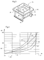
- a cable head damper 1 consists of a frame 2 made of plastic with inserted threaded bolt 3 made of steel. At the long ends 4 namely in the interior 12 of the frame 2 there are molded fixed stops 5. The provided with a conical recess 7 and side jaws 8 Fixed stops 5 carry rubber buffers 6. These can either be attached or vulcanized. The recess 7 is filled with the rubber buffer 6.
- the rubber buffers 6 have two different functional areas 10, 11 due to a conical, flattened cam 9 and due to side stops 9.1 on.
- the side stops 9.1 are reset relative to the cam 9 and lie at right angles to the main axis 13.
- the central, projecting area 10 with the cam 9 describes the progressivity of spring characteristics described for FIG. 4 42 to 45.
- the lateral areas 11 with the side stops 9.1 serve as end buffers.
- the thickness of the buffer zones of the areas 10 to 11 behave as 10 to 1, whereby the area 11 located on the buffer 6 has a thickness of 1 mm and the area 10 has the thickness of 10mm.
- a free distance 27 between the fixed stops 5 is 1.25 times that Length 28 of the sliding carriage 15.
- the sliding carriage 15 has an approximately A-shaped cross section. Its free legs 18 are resilient. At their head and foot ends, they are provided with guide strips 19, 20.
- the tavern! 18 lie over a large area and with a small prestress on the inner guide surfaces 25 of the cheeks 24, each leg 18 with its guide strips 19, 20 gripping the cheek 24 assigned to it approximately in a U-shape.
- the annular, closed frame 2 consists of two mutually parallel Straight guides 22 for the sliding carriage 15 and from two approximately arcuate Sections 23.
- the straight guides 22 are through straight and equally high cheeks 24 formed with inner guide surfaces 25 corresponding to section 26.
- the bottom-shaped sections 23 of the frame 2 are characterized by the block-like Transverse stiffening fixed stops 5 reinforced.
- the frame thus has 2 a large section modulus with little material and weight. At Force is applied to the threaded bolt 3 or via the sliding carriage 15 Dimensional stability of the frame 2 and thus the jam-free mobility of the sliding carriage 15 guaranteed.
- the guide strips 19, 20 of the sliding carriage 15 protrude only slightly above the Frame 2 beyond.
- the recess 7 in the fixed stops 5 enables the soft deflection of the Cam 9 and a short design of the frame 2 and is therefore crucial for the soft spring characteristic of the cam 9.
- the thin elastic layer on the just formed jaws 8 of the fixed stop 5 results in a relatively hard end stop for the Sliding carriage 15.
- the ordinate 40 shows the force in Newtons and the abscissa 41 the path is plotted in mm.
- a characteristic curve 42 there is a defined free path 46 corresponding to the cable head damper 1 according to Figures 1 and 2 before. Between the sliding carriage 15 and there is no friction with the frame 2. When force is applied to the threaded bolt 3 is the frame 2 corresponding to the free path 34 or 34 and 35 to Stop on one of the cams 9 moves. The file is then compressed Cam 9 with a weakly increasing characteristic curve 42, which then turns into a strongly progressive one Characteristic curve 42 passes over to the rigid end stop on the two Side stops 9 ⁇ 1 on the end faces 36 of the tabs 18.
- the characteristic curve 44 defines a cable head damper without free travel with a strongly progressive one Characteristic curve 44.
- a rope head damper without free travel with weakly progressive characteristic 45 lies corresponding to the characteristic curve 45.
- the cam 9 is relatively soft Damping characteristics equipped.
Landscapes
- Engineering & Computer Science (AREA)
- General Engineering & Computer Science (AREA)
- Mechanical Engineering (AREA)
- Health & Medical Sciences (AREA)
- Oral & Maxillofacial Surgery (AREA)
- Vibration Prevention Devices (AREA)
- Vibration Dampers (AREA)
Applications Claiming Priority (2)
| Application Number | Priority Date | Filing Date | Title |
|---|---|---|---|
| DE1998105594 DE19805594A1 (de) | 1998-02-12 | 1998-02-12 | Seilkopf-Dämpfer |
| DE19805594 | 1998-02-12 |
Publications (1)
| Publication Number | Publication Date |
|---|---|
| EP0936364A1 true EP0936364A1 (fr) | 1999-08-18 |
Family
ID=7857407
Family Applications (1)
| Application Number | Title | Priority Date | Filing Date |
|---|---|---|---|
| EP99102326A Withdrawn EP0936364A1 (fr) | 1998-02-12 | 1999-02-06 | Dispositif antivibratoire pour câble de commande |
Country Status (2)
| Country | Link |
|---|---|
| EP (1) | EP0936364A1 (fr) |
| DE (1) | DE19805594A1 (fr) |
Cited By (6)
| Publication number | Priority date | Publication date | Assignee | Title |
|---|---|---|---|---|
| WO2000077412A1 (fr) * | 1999-06-14 | 2000-12-21 | Fritz Himmermann Gmbh & Co.Kg | Fixation pour cable de transmission |
| DE10216903A1 (de) * | 2002-04-17 | 2003-11-13 | Kuester Automotive Control Sys | Anbindungsvorrichtung für einen Betätigungszug an einen Nehmer, insbesondere Zugöse |
| DE102004013193A1 (de) * | 2004-03-17 | 2005-10-13 | Küster Automotive Control Systems GmbH | Anbindungsvorrichtung für einen Betätigungszug an einen Nehmer |
| DE102009041706A1 (de) * | 2009-09-16 | 2011-03-24 | GM Global Technology Operations, Inc., Detroit | Anbindungsvorrichtung für einen Betätigungszug sowie Schaltgetriebe eines Kraftfahrzeugs mit dieser Anbindungsvorrichtung |
| CN105927657A (zh) * | 2016-07-15 | 2016-09-07 | 奇瑞汽车股份有限公司 | 一种换挡拉线接头 |
| US20190285111A1 (en) * | 2018-03-13 | 2019-09-19 | Deere & Company | Push-pull cable structure borne noise isolation |
Citations (5)
| Publication number | Priority date | Publication date | Assignee | Title |
|---|---|---|---|---|
| FR2578600A1 (fr) * | 1985-03-07 | 1986-09-12 | Daimler Benz Ag | Commande a cable bowden |
| US4800773A (en) * | 1985-09-20 | 1989-01-31 | Nissan Motor Co., Ltd. | Accelerator cable connecting device |
| CA1255337A (fr) * | 1984-11-30 | 1989-06-06 | Gordon J. Andry | Ensemble amortisseur |
| US4889006A (en) * | 1988-03-24 | 1989-12-26 | Briggs & Stratton Corporation | Engine speed control cable clip attachment |
| EP0499531A1 (fr) * | 1991-02-13 | 1992-08-19 | Acco La Teledynamique | Commande antivibration à câble flexible |
Family Cites Families (1)
| Publication number | Priority date | Publication date | Assignee | Title |
|---|---|---|---|---|
| DE4037786A1 (de) * | 1990-11-28 | 1992-06-11 | Diehl Gmbh & Co | Schwingungs-tilger |
-
1998
- 1998-02-12 DE DE1998105594 patent/DE19805594A1/de not_active Withdrawn
-
1999
- 1999-02-06 EP EP99102326A patent/EP0936364A1/fr not_active Withdrawn
Patent Citations (5)
| Publication number | Priority date | Publication date | Assignee | Title |
|---|---|---|---|---|
| CA1255337A (fr) * | 1984-11-30 | 1989-06-06 | Gordon J. Andry | Ensemble amortisseur |
| FR2578600A1 (fr) * | 1985-03-07 | 1986-09-12 | Daimler Benz Ag | Commande a cable bowden |
| US4800773A (en) * | 1985-09-20 | 1989-01-31 | Nissan Motor Co., Ltd. | Accelerator cable connecting device |
| US4889006A (en) * | 1988-03-24 | 1989-12-26 | Briggs & Stratton Corporation | Engine speed control cable clip attachment |
| EP0499531A1 (fr) * | 1991-02-13 | 1992-08-19 | Acco La Teledynamique | Commande antivibration à câble flexible |
Cited By (8)
| Publication number | Priority date | Publication date | Assignee | Title |
|---|---|---|---|---|
| WO2000077412A1 (fr) * | 1999-06-14 | 2000-12-21 | Fritz Himmermann Gmbh & Co.Kg | Fixation pour cable de transmission |
| DE10216903A1 (de) * | 2002-04-17 | 2003-11-13 | Kuester Automotive Control Sys | Anbindungsvorrichtung für einen Betätigungszug an einen Nehmer, insbesondere Zugöse |
| DE10216903B4 (de) * | 2002-04-17 | 2004-02-26 | Küster Automotive Control Systems GmbH | Anbindungsvorrichtung für einen Betätigungszug an einen Nehmer, insbesondere Zugöse |
| DE102004013193A1 (de) * | 2004-03-17 | 2005-10-13 | Küster Automotive Control Systems GmbH | Anbindungsvorrichtung für einen Betätigungszug an einen Nehmer |
| DE102009041706A1 (de) * | 2009-09-16 | 2011-03-24 | GM Global Technology Operations, Inc., Detroit | Anbindungsvorrichtung für einen Betätigungszug sowie Schaltgetriebe eines Kraftfahrzeugs mit dieser Anbindungsvorrichtung |
| CN105927657A (zh) * | 2016-07-15 | 2016-09-07 | 奇瑞汽车股份有限公司 | 一种换挡拉线接头 |
| US20190285111A1 (en) * | 2018-03-13 | 2019-09-19 | Deere & Company | Push-pull cable structure borne noise isolation |
| US10662996B2 (en) * | 2018-03-13 | 2020-05-26 | Deere & Company | Push-pull cable arrangement for vibration isolation |
Also Published As
| Publication number | Publication date |
|---|---|
| DE19805594A1 (de) | 1999-08-19 |
Similar Documents
| Publication | Publication Date | Title |
|---|---|---|
| DE10113981A1 (de) | Kraftfahrzeug mit Getriebe | |
| DE7737712U1 (de) | Vorspannbares Lagerelement | |
| DE19731128C2 (de) | Pendelstütze für ein Aggregat in einem Kraftfahrzeug und elastisches Aggregatelager | |
| DE102007005496A1 (de) | Schaltbetätigung für ein Schaltgetriebe | |
| DE102017005845B4 (de) | Rohrförmiges Schwingungsdämpfungselement | |
| DE3808025A1 (de) | Schalthebel | |
| DE102011051976B4 (de) | Schalthebelanordnung eines Automatikgetriebes | |
| DE2703140A1 (de) | Selbstnachstellende scheibenbremse fuer fahrzeuge | |
| DE19805594A1 (de) | Seilkopf-Dämpfer | |
| EP0487972A2 (fr) | Amortisseur d'oscillations | |
| EP2014957B1 (fr) | Dispositif d'actionnement d'une boîte de vitesse de véhicule automobile | |
| EP0442082B1 (fr) | Dispositif de connexion pour une timonerie de changement de vitesse de véhicules automobiles | |
| EP1205692A2 (fr) | Dispositif de changement de vitesses pour transmission multivitesses | |
| DE3634174A1 (de) | Vorrichtung zum daempfen von schwingungen in einer getriebeschaltvorrichtung fuer fahrzeuge | |
| DE19833101B4 (de) | Arretierelement zur Sicherung von Verstellpositionen | |
| DE3109182C1 (de) | Verbindungselement für Schaltgestänge von Kraftfahrzeugen | |
| DE102005030102A1 (de) | Steifigkeitseinstellstruktur eines Übertragungsseils für ein manuelles Getriebe | |
| DE102006003245B4 (de) | Kraftübertragungsgelenk für eine Schaltvorrichtung eines Kraftfahrzeuggetriebes, eine Schaltvorrichtung für ein solches Kraftfahrzeuggetriebe, sowie ein Verfahren zur Herstellung eines Kraftübertragungsgelenks | |
| DE68903883T2 (de) | Schall- und schwingungsdaempfer fuer einen getriebeschalthebel. | |
| WO2008043695A1 (fr) | Procédé de calibrage d'un ressort en élastomère d'un palier, et palier fabriqué d'après ce procédé | |
| AT523025B1 (de) | Mehrstufige Koppelvorrichtung | |
| EP0091608B1 (fr) | Dispositif de désaccouplage pour la tringlerie de changement de vitesse | |
| DE102022108835B4 (de) | Kupplungsbetätigungsvorrichtung | |
| DE19923834A1 (de) | Betätigungsgestänge | |
| WO2019068853A1 (fr) | Système de découplage d'oscillations |
Legal Events
| Date | Code | Title | Description |
|---|---|---|---|
| PUAI | Public reference made under article 153(3) epc to a published international application that has entered the european phase |
Free format text: ORIGINAL CODE: 0009012 |
|
| 17P | Request for examination filed |
Effective date: 19990608 |
|
| AK | Designated contracting states |
Kind code of ref document: A1 Designated state(s): DE FR GB IT |
|
| AX | Request for extension of the european patent |
Free format text: AL;LT;LV;MK;RO;SI |
|
| AKX | Designation fees paid |
Free format text: DE FR GB IT |
|
| STAA | Information on the status of an ep patent application or granted ep patent |
Free format text: STATUS: THE APPLICATION IS DEEMED TO BE WITHDRAWN |
|
| 18D | Application deemed to be withdrawn |
Effective date: 20010901 |