EP0936409A2 - Conduit de fumée pour un appareil de chauffage - Google Patents
Conduit de fumée pour un appareil de chauffage Download PDFInfo
- Publication number
- EP0936409A2 EP0936409A2 EP98120876A EP98120876A EP0936409A2 EP 0936409 A2 EP0936409 A2 EP 0936409A2 EP 98120876 A EP98120876 A EP 98120876A EP 98120876 A EP98120876 A EP 98120876A EP 0936409 A2 EP0936409 A2 EP 0936409A2
- Authority
- EP
- European Patent Office
- Prior art keywords
- heater
- exhaust gas
- exhaust
- flow control
- flow
- Prior art date
- Legal status (The legal status is an assumption and is not a legal conclusion. Google has not performed a legal analysis and makes no representation as to the accuracy of the status listed.)
- Granted
Links
- 238000010438 heat treatment Methods 0.000 title 1
- 239000007789 gas Substances 0.000 claims description 48
- 238000002485 combustion reaction Methods 0.000 claims description 12
- 238000009434 installation Methods 0.000 claims description 8
- 230000001419 dependent effect Effects 0.000 claims description 4
- 238000001514 detection method Methods 0.000 claims description 4
- UGFAIRIUMAVXCW-UHFFFAOYSA-N Carbon monoxide Chemical compound [O+]#[C-] UGFAIRIUMAVXCW-UHFFFAOYSA-N 0.000 abstract 5
- 239000003546 flue gas Substances 0.000 abstract 5
- 239000003570 air Substances 0.000 description 18
- 239000012080 ambient air Substances 0.000 description 2
- 238000011144 upstream manufacturing Methods 0.000 description 2
- 238000009825 accumulation Methods 0.000 description 1
- 239000000567 combustion gas Substances 0.000 description 1
- 238000011161 development Methods 0.000 description 1
- 230000018109 developmental process Effects 0.000 description 1
- 239000000446 fuel Substances 0.000 description 1
- 239000002737 fuel gas Substances 0.000 description 1
- 239000000203 mixture Substances 0.000 description 1
- 238000009419 refurbishment Methods 0.000 description 1
Images
Classifications
-
- F—MECHANICAL ENGINEERING; LIGHTING; HEATING; WEAPONS; BLASTING
- F24—HEATING; RANGES; VENTILATING
- F24H—FLUID HEATERS, e.g. WATER OR AIR HEATERS, HAVING HEAT-GENERATING MEANS, e.g. HEAT PUMPS, IN GENERAL
- F24H9/00—Details
- F24H9/20—Arrangement or mounting of control or safety devices
- F24H9/2007—Arrangement or mounting of control or safety devices for water heaters
- F24H9/2035—Arrangement or mounting of control or safety devices for water heaters using fluid fuel
- F24H9/2042—Preventing or detecting the return of combustion gases
-
- F—MECHANICAL ENGINEERING; LIGHTING; HEATING; WEAPONS; BLASTING
- F23—COMBUSTION APPARATUS; COMBUSTION PROCESSES
- F23M—CASINGS, LININGS, WALLS OR DOORS SPECIALLY ADAPTED FOR COMBUSTION CHAMBERS, e.g. FIREBRIDGES; DEVICES FOR DEFLECTING AIR, FLAMES OR COMBUSTION PRODUCTS IN COMBUSTION CHAMBERS; SAFETY ARRANGEMENTS SPECIALLY ADAPTED FOR COMBUSTION APPARATUS; DETAILS OF COMBUSTION CHAMBERS, NOT OTHERWISE PROVIDED FOR
- F23M11/00—Safety arrangements
-
- F—MECHANICAL ENGINEERING; LIGHTING; HEATING; WEAPONS; BLASTING
- F23—COMBUSTION APPARATUS; COMBUSTION PROCESSES
- F23M—CASINGS, LININGS, WALLS OR DOORS SPECIALLY ADAPTED FOR COMBUSTION CHAMBERS, e.g. FIREBRIDGES; DEVICES FOR DEFLECTING AIR, FLAMES OR COMBUSTION PRODUCTS IN COMBUSTION CHAMBERS; SAFETY ARRANGEMENTS SPECIALLY ADAPTED FOR COMBUSTION APPARATUS; DETAILS OF COMBUSTION CHAMBERS, NOT OTHERWISE PROVIDED FOR
- F23M9/00—Baffles or deflectors for air or combustion products; Flame shields
- F23M9/003—Baffles or deflectors for air or combustion products; Flame shields in flue gas ducts
- F23M9/006—Backflow diverters
-
- F—MECHANICAL ENGINEERING; LIGHTING; HEATING; WEAPONS; BLASTING
- F24—HEATING; RANGES; VENTILATING
- F24H—FLUID HEATERS, e.g. WATER OR AIR HEATERS, HAVING HEAT-GENERATING MEANS, e.g. HEAT PUMPS, IN GENERAL
- F24H15/00—Control of fluid heaters
- F24H15/10—Control of fluid heaters characterised by the purpose of the control
- F24H15/112—Preventing or detecting blocked flues
-
- F—MECHANICAL ENGINEERING; LIGHTING; HEATING; WEAPONS; BLASTING
- F24—HEATING; RANGES; VENTILATING
- F24H—FLUID HEATERS, e.g. WATER OR AIR HEATERS, HAVING HEAT-GENERATING MEANS, e.g. HEAT PUMPS, IN GENERAL
- F24H15/00—Control of fluid heaters
- F24H15/20—Control of fluid heaters characterised by control inputs
- F24H15/235—Temperature of exhaust gases
-
- F—MECHANICAL ENGINEERING; LIGHTING; HEATING; WEAPONS; BLASTING
- F24—HEATING; RANGES; VENTILATING
- F24H—FLUID HEATERS, e.g. WATER OR AIR HEATERS, HAVING HEAT-GENERATING MEANS, e.g. HEAT PUMPS, IN GENERAL
- F24H15/00—Control of fluid heaters
- F24H15/30—Control of fluid heaters characterised by control outputs; characterised by the components to be controlled
- F24H15/355—Control of heat-generating means in heaters
- F24H15/36—Control of heat-generating means in heaters of burners
-
- F—MECHANICAL ENGINEERING; LIGHTING; HEATING; WEAPONS; BLASTING
- F23—COMBUSTION APPARATUS; COMBUSTION PROCESSES
- F23J—REMOVAL OR TREATMENT OF COMBUSTION PRODUCTS OR COMBUSTION RESIDUES; FLUES
- F23J2211/00—Flue gas duct systems
- F23J2211/10—Balanced flues (combining air supply and flue gas exhaust)
- F23J2211/101—Balanced flues (combining air supply and flue gas exhaust) with coaxial duct arrangement
Definitions
- the invention is based on an exhaust gas duct and a Heater with exhaust system according to the genus Main claims. It is known that in particular atmospheric heaters are part of the Exhaust gas routing is designed as a flow safety device (e.g. G 88 01 994.2). Such designed as exhaust hoods Flow fuses have side openings, so in the event of a backflow of the exhaust gases through the openings in can reach the installation room. Near the Exhaust gas sensors located in the openings record the exhaust gas flow and the heater is disabled until the fault is rectified Operation set. In addition, the one Room air dependent heater through the chimney draft caused pressure fluctuations by the in the Flow protection arranged openings balanced.
- a flow safety device e.g. G 88 01 994.2
- the exhaust gas routing according to the invention and the one according to the invention Heater with such an exhaust system have the Advantage that the height of the heater is not essential is increased.
- the one equipped with the flow safety device Room air dependent heater on a room air independent Exterior wall heater to convert by the flow fuse removed and through an air-exhaust system, in the form of a coaxial double tube is replaced.
- the heater itself does not need to be modified.
- the opening for decoupling the heater from the Heater connected exhaust system is more advantageous Way at the top of the first connector of the Flow protection arranged.
- the Pressure decoupling immediately behind the exhaust pipe of the Heater instead, so that in the direction of flow seen behind the opening part of the exhaust system no high tightness requirements have to be made.
- the opening is on the side of the first connection piece an exhaust gas sensor for the detection of back-up exhaust gas intended.
- the heater Air box surround so that in the event of a leak Exhaust gas parts is prevented from exhaust gas in the Installation room of the heater can occur.
- the air box itself is an opening for the exhaust gas routing of the heater provided, the diameter of the opening being chosen so is that between the opening edges and the passed exhaust gas duct results in an annular gap that the Supply of combustion air for the fan-assisted Heater guaranteed.
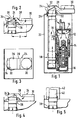
- FIG. 1 shows the heater according to the invention with the exhaust gas routing according to the invention
- Figure 2 a sectional side view of the exhaust system with a Representation of the air and exhaust gas flows in normal operation
- Figure 3 is a plan view of the exhaust system
- Figure 4 is a Representation of the exhaust gas flows within the exhaust system Backflow of exhaust gases
- Figure 5 an alternative Exhaust gas routing for the heater shown in Figure 1 use as an external wall unit independent of ambient air.
- the heater according to Figure 1 has a burner 10, the one Fuel gas-air mixture by a fan, not shown is fed.
- the burner 10 sits at the top of one Combustion chamber 12 by a heat exchanger unit 14 after bottom and side is completed.
- an exhaust gas space 16 is arranged on the lowest point of which is not shown Condensate drainage is provided.
- the Burner and heat exchanger unit and exhaust pipe 18 are surrounded by an air box 20, which at its upper End of an opening 22 for the passage of the exhaust pipe 18th to the outside.
- the diameter of the opening 22 is so dimensioned that between the exhaust pipe 18 and Forms an annular gap over the opening edges Operation of the heater using the burner 10 upstream fan combustion air are sucked in can.
- At the level of the opening 22 made in the air box 20 is connected to the exhaust pipe when viewed in the direction of flow 18 a flow control described in more detail below 24 on.
- the flow fuse 24 has a first connection piece 26, which is gas-tight with the end of the exhaust pipe 18 connected is.
- the in the first connection piece 26th forming flow channel is via a connector 28 performed in a second connection piece 30, such that the first and the second connecting piece 26, 30 horizontally are staggered.
- the second Connection piece 30 does not connect to one shown chimney or chimney.
- first connection piece 26 At the upper end of the first connection piece 26 is one Opening 32 provided which connects the Flow control 24 or the exhaust system with the Installation room of the heater.
- Exhaust gas sensor 34 for the detection of back-up exhaust gas arranged.
- Baffle 36 for the connector 28 and the second connecting piece 30 flowing into the chimney outlet Exhaust gases provided.
- the extension of the flow protection in horizontal direction is thereby offset X (see Fig. 2) of the two connecting pieces 26 and 30 determined. This results in a flat flow fuse 24, so that the overall height of the heater is not essential overall is enlarged.
- the heater works in the following way: About the the burner 10 upstream fan is from the Installation room of the heater via opening 22 Combustion air and a not shown Gas supply device fuel gas supplied to the burner 10. The arising during combustion in the combustion chamber 12 Combustion gases pass through the heat exchanger unit 14 into the exhaust gas space 16 and are shown as exhaust gases (dash-dotted lines shown) via the exhaust pipe 18 and Flow safety device 24 and the adjoining one Chimney drained to the outside. About that in the first Connection piece 26 arranged opening 32 finds one Pressure decoupling of the heater from the rest Exhaust gas discharge instead; at the same time air comes out of the Installation room via the opening 32 in the exhaust duct, see above that the exhaust gas is diluted and thus the dew point is lowered becomes.
- Exhaust gases reach the exhaust gases through the opening 32 in the installation room of the heater.
- the exhaust gases are detected by the exhaust gas sensor 34 and the heater after a pause of about 20 minutes started again automatically.
- room condensing condensing condensing boiler can be used in old buildings, for example, where one Refurbishment of the chimney has not yet taken place. Is the old chimney with a new air exhaust system replaced or is in the chimney a new air-exhaust system the heater can be integrated simple way in a room independent fully condensing heater.
Landscapes
- Engineering & Computer Science (AREA)
- Chemical & Material Sciences (AREA)
- Combustion & Propulsion (AREA)
- Mechanical Engineering (AREA)
- General Engineering & Computer Science (AREA)
- Thermal Sciences (AREA)
- Physics & Mathematics (AREA)
- Air-Conditioning For Vehicles (AREA)
- Exhaust Gas After Treatment (AREA)
- Sampling And Sample Adjustment (AREA)
- Incineration Of Waste (AREA)
- Regulation And Control Of Combustion (AREA)
- Housings, Intake/Discharge, And Installation Of Fluid Heaters (AREA)
- Air Supply (AREA)
Applications Claiming Priority (2)
| Application Number | Priority Date | Filing Date | Title |
|---|---|---|---|
| DE29802545U DE29802545U1 (de) | 1998-02-14 | 1998-02-14 | Abgasführung für ein Heizgerät |
| DE29802545U | 1998-02-14 |
Publications (3)
| Publication Number | Publication Date |
|---|---|
| EP0936409A2 true EP0936409A2 (fr) | 1999-08-18 |
| EP0936409A3 EP0936409A3 (fr) | 2000-01-12 |
| EP0936409B1 EP0936409B1 (fr) | 2003-06-25 |
Family
ID=8052671
Family Applications (1)
| Application Number | Title | Priority Date | Filing Date |
|---|---|---|---|
| EP98120876A Expired - Lifetime EP0936409B1 (fr) | 1998-02-14 | 1998-11-04 | Conduit de fumée pour un appareil de chauffage |
Country Status (3)
| Country | Link |
|---|---|
| EP (1) | EP0936409B1 (fr) |
| AT (1) | ATE243830T1 (fr) |
| DE (2) | DE29802545U1 (fr) |
Cited By (2)
| Publication number | Priority date | Publication date | Assignee | Title |
|---|---|---|---|---|
| EP1434017A1 (fr) * | 2002-12-23 | 2004-06-30 | MERLONI TERMOSANITARI S.p.A. | Chaudiére murale à air soufflé |
| EP1434015A3 (fr) * | 2002-12-23 | 2004-12-29 | MERLONI TERMOSANITARI S.p.A. | Chaudière murale universelle, standard à condensation partielle ou totale |
Families Citing this family (1)
| Publication number | Priority date | Publication date | Assignee | Title |
|---|---|---|---|---|
| ES2960744T3 (es) * | 2019-12-04 | 2024-03-06 | Vaillant Gmbh | Artefacto de calefacción a gas con detector de gases nocivos |
Citations (1)
| Publication number | Priority date | Publication date | Assignee | Title |
|---|---|---|---|---|
| DE8801994U1 (de) | 1987-02-17 | 1988-03-24 | Joh. Vaillant Gmbh U. Co, 5630 Remscheid | Abgasführung mit Leitschaufeln |
Family Cites Families (7)
| Publication number | Priority date | Publication date | Assignee | Title |
|---|---|---|---|---|
| GB546201A (en) * | 1941-04-19 | 1942-07-01 | Norman Grater | Improvements in or relating to vertical gas fired tubular boilers |
| AU1030466A (en) * | 1967-06-07 | 1968-12-12 | Rheem Australia Pty. Limited | Improvements in diverter assemblies for gas water heaters |
| DE3008399A1 (de) * | 1980-03-05 | 1981-09-17 | Küppersbusch AG, 4650 Gelsenkirchen | Gas-raumheizungsgeraet |
| US4403599A (en) * | 1980-11-18 | 1983-09-13 | Carrier Corporation | Spillage damper for a combustion system |
| IT1241083B (it) * | 1990-03-23 | 1993-12-29 | Nuovo Pignone Spa | Caldaia murale forzata stagna a gas perfezionata,per uso domestico |
| DE9301720U1 (de) * | 1992-02-13 | 1993-04-22 | Joh. Vaillant Gmbh U. Co, 5630 Remscheid | Heizgerät |
| FR2736995B1 (fr) * | 1995-07-21 | 1997-08-22 | Formastim Sa Soc | Appareil pour transformer les circuits gazeux de chaudieres classiques en circuits gazeux etanches, ameliorant le rendement de combustion et reduisant les emissions d'imbrules |
-
1998
- 1998-02-14 DE DE29802545U patent/DE29802545U1/de not_active Expired - Lifetime
- 1998-11-04 AT AT98120876T patent/ATE243830T1/de not_active IP Right Cessation
- 1998-11-04 EP EP98120876A patent/EP0936409B1/fr not_active Expired - Lifetime
- 1998-11-04 DE DE59808814T patent/DE59808814D1/de not_active Expired - Lifetime
Patent Citations (1)
| Publication number | Priority date | Publication date | Assignee | Title |
|---|---|---|---|---|
| DE8801994U1 (de) | 1987-02-17 | 1988-03-24 | Joh. Vaillant Gmbh U. Co, 5630 Remscheid | Abgasführung mit Leitschaufeln |
Cited By (2)
| Publication number | Priority date | Publication date | Assignee | Title |
|---|---|---|---|---|
| EP1434017A1 (fr) * | 2002-12-23 | 2004-06-30 | MERLONI TERMOSANITARI S.p.A. | Chaudiére murale à air soufflé |
| EP1434015A3 (fr) * | 2002-12-23 | 2004-12-29 | MERLONI TERMOSANITARI S.p.A. | Chaudière murale universelle, standard à condensation partielle ou totale |
Also Published As
| Publication number | Publication date |
|---|---|
| EP0936409A3 (fr) | 2000-01-12 |
| DE59808814D1 (de) | 2003-07-31 |
| DE29802545U1 (de) | 1999-06-17 |
| ATE243830T1 (de) | 2003-07-15 |
| EP0936409B1 (fr) | 2003-06-25 |
Similar Documents
| Publication | Publication Date | Title |
|---|---|---|
| EP2312213B1 (fr) | Dispositif de réglage pour brûleur à gaz | |
| EP0936409B1 (fr) | Conduit de fumée pour un appareil de chauffage | |
| EP1746345B1 (fr) | Procédé de fonctionnement d'un brûleur à gaz | |
| DE4334625A1 (de) | Verfahren zum Konstanthalten der Leistung eines Wassererwärmers | |
| DE102021110061A1 (de) | Anordnung zur Verminderung der Folgen eines Flammenrückschlages in einen Vormisch-Brenner eines Heizgerätes | |
| DE3308700A1 (de) | Einrichtung zum heizen und lueften | |
| EP1039244B1 (fr) | Dispositif de chauffage avec pile à combustible | |
| EP0434599B1 (fr) | Brûleur à gaz prémélangé | |
| DE3402760A1 (de) | Im freien verwendbarer kocher, insbesondere gaskocher | |
| DE3803092C1 (en) | Mixing nozzle of a gas burner for a gas heating appliance | |
| EP1241408B1 (fr) | Brûleur pour un mélange air-gaz | |
| DE3411038C2 (fr) | ||
| EP0793063A1 (fr) | Installation de chauffage avec échangeur de chaleur | |
| EP0445393B1 (fr) | Brûleur avec récirculation des gaz d'échappement, notamment brûleur à air soufflé | |
| EP0314972B1 (fr) | Appareil pour chauffer de l'eau notamment une chaudière de chauffage d'eau chaude | |
| DE3345202A1 (de) | Vorrichtung zur herabsetzung der taupunkttemperatur von abgasen | |
| EP0859204A2 (fr) | Appareil de chauffage pour chauffe-eau | |
| DE19754581C2 (de) | Heizgerät | |
| DE4237719C2 (de) | Atmosphärischer Gasbrenner | |
| DE2946501A1 (de) | Abgassystem fuer raumheizgeraete | |
| EP2687784B1 (fr) | Système doté d'un dispositif de gaz d'échappement et procédé de fonctionnement d'un tel système | |
| DE3036506A1 (de) | Abgashaube, insbesondere fuer ein gas-heizgeraet | |
| DE29608984U1 (de) | Heizgerät | |
| DE2920338A1 (de) | Abgas-stroemungssicherung fuer einen heizkessel mit geblaesebrenner | |
| AT508207B1 (de) | Wohnungslüftung |
Legal Events
| Date | Code | Title | Description |
|---|---|---|---|
| PUAI | Public reference made under article 153(3) epc to a published international application that has entered the european phase |
Free format text: ORIGINAL CODE: 0009012 |
|
| AK | Designated contracting states |
Kind code of ref document: A2 Designated state(s): AT CH DE ES FR GB IT LI NL |
|
| AX | Request for extension of the european patent |
Free format text: AL;LT;LV;MK;RO;SI |
|
| PUAL | Search report despatched |
Free format text: ORIGINAL CODE: 0009013 |
|
| AK | Designated contracting states |
Kind code of ref document: A3 Designated state(s): AT BE CH CY DE DK ES FI FR GB GR IE IT LI LU MC NL PT SE |
|
| AX | Request for extension of the european patent |
Free format text: AL;LT;LV;MK;RO;SI |
|
| 17P | Request for examination filed |
Effective date: 20000712 |
|
| AKX | Designation fees paid |
Free format text: AT CH DE ES FR GB IT LI NL |
|
| 17Q | First examination report despatched |
Effective date: 20020102 |
|
| GRAH | Despatch of communication of intention to grant a patent |
Free format text: ORIGINAL CODE: EPIDOS IGRA |
|
| GRAH | Despatch of communication of intention to grant a patent |
Free format text: ORIGINAL CODE: EPIDOS IGRA |
|
| GRAA | (expected) grant |
Free format text: ORIGINAL CODE: 0009210 |
|
| AK | Designated contracting states |
Designated state(s): AT CH DE ES FR GB IT LI NL |
|
| PG25 | Lapsed in a contracting state [announced via postgrant information from national office to epo] |
Ref country code: NL Free format text: LAPSE BECAUSE OF FAILURE TO SUBMIT A TRANSLATION OF THE DESCRIPTION OR TO PAY THE FEE WITHIN THE PRESCRIBED TIME-LIMIT Effective date: 20030625 |
|
| REG | Reference to a national code |
Ref country code: GB Ref legal event code: FG4D Free format text: NOT ENGLISH |
|
| REG | Reference to a national code |
Ref country code: CH Ref legal event code: EP |
|
| REF | Corresponds to: |
Ref document number: 59808814 Country of ref document: DE Date of ref document: 20030731 Kind code of ref document: P |
|
| PG25 | Lapsed in a contracting state [announced via postgrant information from national office to epo] |
Ref country code: AT Free format text: LAPSE BECAUSE OF NON-PAYMENT OF DUE FEES Effective date: 20031104 |
|
| GBT | Gb: translation of ep patent filed (gb section 77(6)(a)/1977) |
Effective date: 20031022 |
|
| PG25 | Lapsed in a contracting state [announced via postgrant information from national office to epo] |
Ref country code: LI Free format text: LAPSE BECAUSE OF NON-PAYMENT OF DUE FEES Effective date: 20031130 Ref country code: CH Free format text: LAPSE BECAUSE OF NON-PAYMENT OF DUE FEES Effective date: 20031130 |
|
| NLV1 | Nl: lapsed or annulled due to failure to fulfill the requirements of art. 29p and 29m of the patents act | ||
| PG25 | Lapsed in a contracting state [announced via postgrant information from national office to epo] |
Ref country code: ES Free format text: LAPSE BECAUSE OF FAILURE TO SUBMIT A TRANSLATION OF THE DESCRIPTION OR TO PAY THE FEE WITHIN THE PRESCRIBED TIME-LIMIT Effective date: 20031222 |
|
| ET | Fr: translation filed | ||
| PLBE | No opposition filed within time limit |
Free format text: ORIGINAL CODE: 0009261 |
|
| STAA | Information on the status of an ep patent application or granted ep patent |
Free format text: STATUS: NO OPPOSITION FILED WITHIN TIME LIMIT |
|
| 26N | No opposition filed |
Effective date: 20040326 |
|
| REG | Reference to a national code |
Ref country code: CH Ref legal event code: PL |
|
| PGFP | Annual fee paid to national office [announced via postgrant information from national office to epo] |
Ref country code: GB Payment date: 20101123 Year of fee payment: 13 Ref country code: IT Payment date: 20101124 Year of fee payment: 13 |
|
| PGFP | Annual fee paid to national office [announced via postgrant information from national office to epo] |
Ref country code: FR Payment date: 20111125 Year of fee payment: 14 |
|
| GBPC | Gb: european patent ceased through non-payment of renewal fee |
Effective date: 20121104 |
|
| REG | Reference to a national code |
Ref country code: FR Ref legal event code: ST Effective date: 20130731 |
|
| PG25 | Lapsed in a contracting state [announced via postgrant information from national office to epo] |
Ref country code: IT Free format text: LAPSE BECAUSE OF NON-PAYMENT OF DUE FEES Effective date: 20121104 |
|
| PG25 | Lapsed in a contracting state [announced via postgrant information from national office to epo] |
Ref country code: FR Free format text: LAPSE BECAUSE OF NON-PAYMENT OF DUE FEES Effective date: 20121130 Ref country code: GB Free format text: LAPSE BECAUSE OF NON-PAYMENT OF DUE FEES Effective date: 20121104 |
|
| PGFP | Annual fee paid to national office [announced via postgrant information from national office to epo] |
Ref country code: DE Payment date: 20160126 Year of fee payment: 18 |
|
| REG | Reference to a national code |
Ref country code: DE Ref legal event code: R119 Ref document number: 59808814 Country of ref document: DE |
|
| PG25 | Lapsed in a contracting state [announced via postgrant information from national office to epo] |
Ref country code: DE Free format text: LAPSE BECAUSE OF NON-PAYMENT OF DUE FEES Effective date: 20170601 |