EP0936450A1 - Anordnung zur Bestimmung des Massendurchflusses eines gasförmigen Mediums - Google Patents
Anordnung zur Bestimmung des Massendurchflusses eines gasförmigen Mediums Download PDFInfo
- Publication number
- EP0936450A1 EP0936450A1 EP98810022A EP98810022A EP0936450A1 EP 0936450 A1 EP0936450 A1 EP 0936450A1 EP 98810022 A EP98810022 A EP 98810022A EP 98810022 A EP98810022 A EP 98810022A EP 0936450 A1 EP0936450 A1 EP 0936450A1
- Authority
- EP
- European Patent Office
- Prior art keywords
- arrangement according
- container
- determining
- gaseous medium
- gas
- Prior art date
- Legal status (The legal status is an assumption and is not a legal conclusion. Google has not performed a legal analysis and makes no representation as to the accuracy of the status listed.)
- Granted
Links
- 238000005303 weighing Methods 0.000 claims abstract description 15
- 238000011156 evaluation Methods 0.000 claims description 6
- 239000000696 magnetic material Substances 0.000 claims description 4
- 230000000694 effects Effects 0.000 claims description 3
- 238000005259 measurement Methods 0.000 abstract description 6
- 238000001739 density measurement Methods 0.000 abstract 1
- 239000007789 gas Substances 0.000 description 33
- VNWKTOKETHGBQD-UHFFFAOYSA-N methane Chemical compound C VNWKTOKETHGBQD-UHFFFAOYSA-N 0.000 description 30
- 239000003345 natural gas Substances 0.000 description 15
- 238000000034 method Methods 0.000 description 4
- 230000001419 dependent effect Effects 0.000 description 2
- 239000000835 fiber Substances 0.000 description 2
- 239000000446 fuel Substances 0.000 description 2
- 239000004033 plastic Substances 0.000 description 2
- 229920000049 Carbon (fiber) Polymers 0.000 description 1
- XAGFODPZIPBFFR-UHFFFAOYSA-N aluminium Chemical compound [Al] XAGFODPZIPBFFR-UHFFFAOYSA-N 0.000 description 1
- 229910052782 aluminium Inorganic materials 0.000 description 1
- 238000005452 bending Methods 0.000 description 1
- 239000004917 carbon fiber Substances 0.000 description 1
- 239000002131 composite material Substances 0.000 description 1
- 239000003822 epoxy resin Substances 0.000 description 1
- 239000002245 particle Substances 0.000 description 1
- 229920000647 polyepoxide Polymers 0.000 description 1
- 230000029058 respiratory gaseous exchange Effects 0.000 description 1
Images
Classifications
-
- G—PHYSICS
- G01—MEASURING; TESTING
- G01F—MEASURING VOLUME, VOLUME FLOW, MASS FLOW OR LIQUID LEVEL; METERING BY VOLUME
- G01F1/00—Measuring the volume flow or mass flow of fluid or fluent solid material wherein the fluid passes through a meter in a continuous flow
- G01F1/76—Devices for measuring mass flow of a fluid or a fluent solid material
- G01F1/86—Indirect mass flowmeters, e.g. measuring volume flow and density, temperature or pressure
- G01F1/90—Indirect mass flowmeters, e.g. measuring volume flow and density, temperature or pressure with positive-displacement meter or turbine meter to determine the volume flow
-
- G—PHYSICS
- G01—MEASURING; TESTING
- G01F—MEASURING VOLUME, VOLUME FLOW, MASS FLOW OR LIQUID LEVEL; METERING BY VOLUME
- G01F1/00—Measuring the volume flow or mass flow of fluid or fluent solid material wherein the fluid passes through a meter in a continuous flow
- G01F1/76—Devices for measuring mass flow of a fluid or a fluent solid material
- G01F1/86—Indirect mass flowmeters, e.g. measuring volume flow and density, temperature or pressure
Definitions
- the invention relates to an arrangement for determining the Mass flow of a gaseous medium.
- Flowmeters used on the Coriolis principle based With such devices, one or several pipes through which the gas flows Vibration offset. This acts on the flowing gas a Coriolis force that causes the Vibrations of the tube or tubes in one of the Change mass flow dependent manner.
- the Coriolis measuring devices thus allow a direct measurement of the Mass flow of gas. Be electronic Generates pulses that are proportional to the mass of the are flowing gas and then for example can be fed to a fuel column counter.
- Such on mass flow meters based on the Coriolis principle are, however, very complex and also costly Devices that are also relatively sensitive to exterior Interferences react. You make a significant one Cost factor for gas refueling systems.
- the arrangement is also for under high Gases under pressure may be suitable.
- the arrangement thus includes one Device for determining the density of the gaseous Medium, a device for determining the Volume flow of the gaseous medium and a Connection line between these two devices.
- the Determination of the mass flow not by a direct measurement, but in two steps: firstly the current density or the operating density of the gaseous flowing medium determined and on the other there is a volumetric flow measurement. From these The mass flow can be determined in both sizes.
- This measure is the inventive one Arrangement, especially compared to that on the Coriolis principle based measuring devices, especially simple and inexpensive.
- the density of the gaseous medium is determined preferably by weighing a precisely known volume, which is flowed through by the gaseous medium.
- the volumetric flow measurement is preferably carried out by means of a rotor arranged in the gas stream, the has multiple blades and a magnetic material includes.
- a sensitive to magnetic fields Converter e.g. B. a Hall sensor, the Rotational movement of the blades in electrical signals implemented so that the speed of the rotor and thus the Volume flow can be determined.
- the arrangement according to the invention is particularly for Suitable for gas refueling systems.
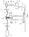
- Fig. 1 shows a schematic representation Embodiment of the inventive arrangement for Determination of the mass flow of a gaseous Medium, all with the reference number 1 is designated.
- the arrangement 1 comprises a device 2 for determining the density of the gaseous medium, a Device 3 for determining the volume flow of the gaseous medium and a connecting line 4 between these two devices 2,3.
- the device 2 for determining the density comprises one Weighing device 22 and a container 21 with a constant and known volume.
- the container 21 has one Inlet 23 and an outlet 24 for the gaseous Medium and is arranged in such a way that its current Weight, which in the operating state is the sum of its Own or empty weight and the weight of the inside of the Container 21 located gaseous medium meant can be determined by means of the weighing device 22.
- Weighing device 22 configured as a platform which of the containers 21 stands so that it is the platform loaded with his weight.
- a force sensor such as a strain gauge or a strain gauge bridge circuit is provided, for a precise determination of the current weight of the To enable container 21.
- the means of Weighing device 22 certain measurement data are via a or several signal lines 7 of an evaluation unit 5 transmitted where the data z. B. electronically processed and evaluated.
- the inlet 23 of the container 21 is with a Feed line 9 and the outlet 24 with a Leakage line 4 connected.
- the feed line 9 leads for example to a storage unit 6 in which the gaseous medium is in stock.
- a storage unit 6 in which the gaseous medium is in stock.
- the storage unit 6 Storage vessel from which the gas when refueling the Motor vehicle flows in its tank, so corresponds the storage unit, which in EP-A-653 585 with the Reference number 3 is provided.
- the lines 4,9 and the container 21 are pressure-resistant are designed.
- these lines are 4.9 flexibly designed or flexible with inlet 23 or the outlet 24 of the container 21, so that they do not significantly interfere with the weighing of the container 21 cause.
- the exemplary embodiment forms the discharge line 4 Connection line, which the two devices 2,3 connects with each other.
- a device 3 for determining the volume flow are basically all known per se Volume flow meter suitable.
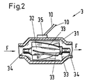
- the following is below Referring to Figure 2, a particularly preferred one Design described in which a pressure-resistant non-magnetic, in particular metallic, housing 31 is provided in which a rotor 32 with several Paddles 33 is arranged, which is a magnetic Material includes.
- the device 3 also has a transducer sensitive to magnetic fields, preferably a Hall sensor 35 on which the movement of the blades 33 converts into electrical signals that via Signal lines 10 of the evaluation unit 5 (FIG. 1) be fed.
- the Hall sensor is for practical reasons 35 preferably on the outside of the housing 31 arranged.
- the one shown in Fig. 2 The embodiment is the rotor 32 as an axial turbine designed.
- the rotor 32 trains as a vane turbine.
- the rotor 32 runs in axial direction on both sides in a shaft 34.
- the Shafts 34 are each represented by a not shown Pin bearing held.
- the rotor 32 is by the flowing gaseous medium, its direction of flow is indicated by the arrows F, set in rotation.
- the blades 33 or the entire rotor 32 are magnetizable or permanent magnetic Properties on.
- the rotor 32 with the blades 33 can be made of a plastic, for example the plastic stored and / or on its surface provided magnetic materials, e.g. B. in Particle shape. At least the blades 33 of the Rotors 32 must be designed so that they (in Operating state) permanently generate a magnetic field.
- the speed of the rotor 32 is substantially proportional to the volume of the gas flowing through it. If the rotor 32 rotates, so is the rotating the blades 33 past the Hall sensor 35 can be detected by means of this, so that the Speed of the rotor 32 and thus the volume flow of the gaseous medium can be determined.
- the compressed natural gas is under one Operating pressure of typically more than 100 bar, for example between 200 and 300 bar (based on a Temperature of 15 ° C), in the storage unit 6.
- the Components of the arrangement 1, made by the natural gas are flowed through, e.g. B. the container 21 and the Lines 9.4 and 11 are designed such that they withstand this operating pressure.
- the gas After flowing through the container 21, the gas flows in the essentially at the same pressure and temperature through the housing 31 of the device 3 and offset thereby rotating the rotor 32.
- the speed of the rotor 32 is determined from which determine the volume flow of natural gas leaves.
- the evaluation unit 5 then turns the current density of natural gas and volume flow the mass flow is calculated and, for example, as Signal via a signal line 8 of a display device fed to the gas refueling system.
- the evaluation unit 5 preferably comprises both from the device 2 for determining the density as well from the device 3 for determining the Volume flow receives signals, electronic means to multiply the current density signal by Volume flow signal, so the signal for the To determine mass flow.
- the two devices 2 and 3 and the Connection line 4 are designed and relative arranged to each other that between the inlet of the Container 21 and the outlet of the housing 31 of the Device 3 no significant pressure gradient and none there is a significant temperature gradient, so that Natural gas, the two devices 2 and 3 essentially under the same pressure and at the same temperature flows through.
- the inlet 23 and / or the outlet 24 are preferred Container 21 designed such that the by flowing gaseous medium caused recoil effect is minimal.
- the inlet 23 designed so that it first as a tube into the interior of the container 21 extends and there a T-shaped end with two Has inlet openings 23a and 23b.
- the two Inlet openings are so arranged that the through the gas flowing in an inlet opening 23a flows essentially in the opposite direction like the gas flowing through the other inlet port 23b.
- the container 21 has a ratio of Has its own weight and volume that is less than 1 kg / l, in particular less than 0.5 kg / l.
- Such Container 21 that meet this condition and also for the high operating pressures mentioned above, e.g. B. to 300 bar, are suitable from the prior art known, for example as so-called composite bottles. These are pressure bottles that are a thin aluminum bottle (so-called liner), which are of high strength Fibers, e.g. B. carbon fibers, surrounded, these Fibers are cast in an epoxy resin. Such Bottles are typically called breathing air bottles used. Your ratio of weight to volume is particularly small, for example 0.3 kg / l.
- the relative arrangement of the two Devices 2 and 3 to each other in the flow direction of the gaseous medium are exchanged, so that gaseous medium first the device 3 for determining of volume flow and then the device 2 for Determine the density of flow.
- the device 2 for determining the density in analogously the same way according to the principle of a Bending beam or beam scales are designed, whereby the container 21 then hangs on the scale.
- the container 21 is as possible free-standing or free-hanging and as smooth as possible is arranged.
- the invention is a particularly simple and proposed inexpensive arrangement with which in simple way the mass flow of a gaseous Medium, especially one flowing under high pressure gaseous medium, very accurately and reliably leaves.
- This arrangement is especially for Gas refueling systems and especially those for delivery of compressed natural gas, e.g. B. in the pressure range of 200-300 bar (based on 15 ° C), suitable.
Landscapes
- Physics & Mathematics (AREA)
- Fluid Mechanics (AREA)
- General Physics & Mathematics (AREA)
- Measuring Volume Flow (AREA)
- Filling Or Discharging Of Gas Storage Vessels (AREA)
- Sampling And Sample Adjustment (AREA)
- Other Investigation Or Analysis Of Materials By Electrical Means (AREA)
Abstract
Description
- Fig. 1:
- eine schematische Darstellung eines Ausführungsbeispiels der erfindungsgemässen Anordnung, und
- Fig.2:
- eine Schnittdarstellung eines Ausführungsbeispiels der Vorrichtung zum Bestimmen des Volumendurchflusses.
Claims (11)
- Anordnung zur Bestimmung des Massendurchflusses eines gasförmigen Mediums mit einer Vorrichtung (2) zum Bestimmen der Dichte des gasförmigen Mediums, mit einer Vorrichtung (3) zum Bestimmen des Volumendurchflusses des gasförmigen Mediums, und mit einer Verbindungsleitung (4) zwischen diesen beiden Vorrichtungen (2,3).
- Anordnung nach Anspruch 1, bei welcher die Vorrichtung (2) zum Bestimmen der Dichte eine Wägeeinrichtung (22) umfasst, sowie einen Behälter (21) mit konstantem Volumen, der einen Einlass (23) und einen Auslass (24) für das gasförmige Medium aufweist, wobei der Behälter (21) derart angeordnet ist, dass sein aktuelles Gewicht - inklusive des im Innern des Behälters (21) befindlichen gasförmigen Mediums - mittels der Wägeeinrichtung (22) bestimmbar ist.
- Anordnung nach einem der vorangehenden Ansprüche, bei welcher der Einlass (23) des Behälters (21) mit einer Zuführleitung (9) und der Auslass (24) mit einer Abführleitung (4) verbunden ist, wobei beide Leitungen (4,9) flexibel und druckfest ausgestaltet sind, und wobei eine der beiden Leitungen die Verbindungsleitung (4) bildet.
- Anordnung nach einem der vorangehenden Ansprüche, wobei der Behälter (21) ein Verhältnis aus Eigengewicht und Volumen aufweist, das kleiner als 1 kg/l, insbesondere kleiner als 0.5 kg/l, ist.
- Anordnung nach einem der vorangehenden Ansprüche, wobei der Einlass (23) und/oder der Auslass (24) des Behälters derart ausgestaltet sind, dass der durch das strömende gasförmige Medium verursachte Rückstosseffekt minimal ist.
- Anordnung nach einem der vorangehenden Ansprüche wobei die Vorrichtung (3) zum Bestimmen des Volumendurchflusses ein druckfestes unmagnetisches, insbesondere metallisches, Gehäuse (31) aufweist, in welchem ein Rotor (32) mit mehreren Schaufeln (33) angeordnet ist, der ein magnetisches Material umfasst, und wobei die Vorrichtung (3) ferner einen für Magnetfelder empfindlichen Wandler (35) aufweist, der die Bewegung der Schaufeln (33) in elektrische Signale umsetzt.
- Anordnung nach Anspruch 6, wobei der Wandler (35) an der Aussenseite des Gehäuses (31) angeordnet ist.
- Anordnung nach Anspruch 6 oder 7 wobei der Wandler als Hall-Sensor (35) ausgestaltet ist.
- Anordnung nach einem der vorangehenden Ansprüche, die für einen Betriebsdruck von über 100 bar, insbesondere 200 bis 300 bar, ausgestaltet ist.
- Anordnung nach einem der vorangehenden Ansprüche, mit einer Auswerteeinheit 5, die sowohl von der Vorrichtung 2 zum Bestimmen der Dichte als auch von der Vorrichtung 3 zum Bestimmen des Volumendurchflusses Signale empfängt, wobei die Auswerteeinheit 5 elektonische Mittel zum Multiplizieren des aktuellen Dichtesignals mit dem Volumendurchflusssignal umfasst, um so ein Signal für den Massendurchfluss zu bestimmen.
- Gasbetankungsanlage mit einer Anordnung gemäss einem der vorangehenden Ansprüche.
Priority Applications (10)
| Application Number | Priority Date | Filing Date | Title |
|---|---|---|---|
| EP98810022A EP0936450B1 (de) | 1998-01-20 | 1998-01-20 | Anordnung zur Bestimmung des Massendurchflusses eines gasförmigen Mediums |
| DE59813966T DE59813966D1 (de) | 1998-01-20 | 1998-01-20 | Anordnung zur Bestimmung des Massendurchflusses eines gasförmigen Mediums |
| AT98810022T ATE359495T1 (de) | 1998-01-20 | 1998-01-20 | Anordnung zur bestimmung des massendurchflusses eines gasförmigen mediums |
| NZ333338A NZ333338A (en) | 1998-01-20 | 1998-12-14 | Arrangement for the determination of the mass through-flow of a gas with apparatus for determining density, typically by weight of known container, line connected to volumetric through-flow apparatus |
| CA002256137A CA2256137C (en) | 1998-01-20 | 1998-12-16 | Arrangement for the determination of the mass through-flow of a gaseous medium |
| JP11001693A JPH11271127A (ja) | 1998-01-20 | 1999-01-07 | ガス状媒体の流量決定装置 |
| ARP990100082A AR014287A1 (es) | 1998-01-20 | 1999-01-11 | Disposicion para determinar el caudal de paso de masa de un fluido gaseoso, y estacion de carga de gas |
| AU11303/99A AU745300B2 (en) | 1998-01-20 | 1999-01-13 | Arrangement for the determination of the mass throughflow of a gaseous medium |
| BR9900117-9A BR9900117A (pt) | 1998-01-20 | 1999-01-19 | Dispositivo para a determinação de fluxo contìnuo de massa de um meio gasoso. |
| KR1019990001628A KR19990068023A (ko) | 1998-01-20 | 1999-01-20 | 가스질매체의 질량 스루플로를 측정하는 설비 |
Applications Claiming Priority (1)
| Application Number | Priority Date | Filing Date | Title |
|---|---|---|---|
| EP98810022A EP0936450B1 (de) | 1998-01-20 | 1998-01-20 | Anordnung zur Bestimmung des Massendurchflusses eines gasförmigen Mediums |
Publications (2)
| Publication Number | Publication Date |
|---|---|
| EP0936450A1 true EP0936450A1 (de) | 1999-08-18 |
| EP0936450B1 EP0936450B1 (de) | 2007-04-11 |
Family
ID=8235895
Family Applications (1)
| Application Number | Title | Priority Date | Filing Date |
|---|---|---|---|
| EP98810022A Expired - Lifetime EP0936450B1 (de) | 1998-01-20 | 1998-01-20 | Anordnung zur Bestimmung des Massendurchflusses eines gasförmigen Mediums |
Country Status (10)
| Country | Link |
|---|---|
| EP (1) | EP0936450B1 (de) |
| JP (1) | JPH11271127A (de) |
| KR (1) | KR19990068023A (de) |
| AR (1) | AR014287A1 (de) |
| AT (1) | ATE359495T1 (de) |
| AU (1) | AU745300B2 (de) |
| BR (1) | BR9900117A (de) |
| CA (1) | CA2256137C (de) |
| DE (1) | DE59813966D1 (de) |
| NZ (1) | NZ333338A (de) |
Cited By (2)
| Publication number | Priority date | Publication date | Assignee | Title |
|---|---|---|---|---|
| CN109798441A (zh) * | 2019-03-20 | 2019-05-24 | 山东恒昌聚材化工科技股份有限公司 | 一种氢气管束式集装箱车辆充装体积自动计量方法 |
| CN115419823A (zh) * | 2022-09-20 | 2022-12-02 | 济南德洋特种气体有限公司 | 一种气瓶充装追踪管理系统 |
Families Citing this family (1)
| Publication number | Priority date | Publication date | Assignee | Title |
|---|---|---|---|---|
| KR100456908B1 (ko) * | 2002-11-25 | 2004-11-10 | 한국항공우주연구원 | 정압보정 탱크를 이용한 미세유량률 측정용 임펄스 출력식유량계의 정밀 보정장치 및 그 방법 |
Citations (4)
| Publication number | Priority date | Publication date | Assignee | Title |
|---|---|---|---|---|
| GB1345974A (en) * | 1970-07-07 | 1974-02-06 | Diessel Gmbh & Co | Apparatus for measuring the flow of a liquid |
| GB2085597A (en) * | 1980-10-17 | 1982-04-28 | Redland Automation Ltd | Method and apparatus for detemining the mass flow of a fluid |
| GB2102995A (en) * | 1981-07-22 | 1983-02-09 | Euromatic Machine And Oil Co L | Improvements in and relating to flow measurement |
| EP0653585A1 (de) * | 1993-11-08 | 1995-05-17 | Maschinenfabrik Sulzer-Burckhardt AG | Verfahren und Vorrichtung zum schnellen Betanken eines Druckbehälters mit einem gasförmigen Medium |
Family Cites Families (4)
| Publication number | Priority date | Publication date | Assignee | Title |
|---|---|---|---|---|
| US4508127A (en) * | 1983-03-30 | 1985-04-02 | The Garrett Corporation | Fuel mass flow measurement and control system |
| JPH06159595A (ja) * | 1992-11-19 | 1994-06-07 | Tokico Ltd | ガス供給装置 |
| CN201408794Y (zh) * | 2009-04-30 | 2010-02-17 | 比亚迪股份有限公司 | 一种电池防爆阀及电池 |
| KR102102995B1 (ko) * | 2019-07-02 | 2020-04-21 | 전라북도(농업기술원) | 흑미 및 당 발효액을 이용한 흑미 식초의 제조 방법 및 이로부터 수득된 흑미 식초 |
-
1998
- 1998-01-20 AT AT98810022T patent/ATE359495T1/de not_active IP Right Cessation
- 1998-01-20 EP EP98810022A patent/EP0936450B1/de not_active Expired - Lifetime
- 1998-01-20 DE DE59813966T patent/DE59813966D1/de not_active Expired - Fee Related
- 1998-12-14 NZ NZ333338A patent/NZ333338A/xx unknown
- 1998-12-16 CA CA002256137A patent/CA2256137C/en not_active Expired - Fee Related
-
1999
- 1999-01-07 JP JP11001693A patent/JPH11271127A/ja active Pending
- 1999-01-11 AR ARP990100082A patent/AR014287A1/es active IP Right Grant
- 1999-01-13 AU AU11303/99A patent/AU745300B2/en not_active Ceased
- 1999-01-19 BR BR9900117-9A patent/BR9900117A/pt not_active Application Discontinuation
- 1999-01-20 KR KR1019990001628A patent/KR19990068023A/ko not_active Ceased
Patent Citations (4)
| Publication number | Priority date | Publication date | Assignee | Title |
|---|---|---|---|---|
| GB1345974A (en) * | 1970-07-07 | 1974-02-06 | Diessel Gmbh & Co | Apparatus for measuring the flow of a liquid |
| GB2085597A (en) * | 1980-10-17 | 1982-04-28 | Redland Automation Ltd | Method and apparatus for detemining the mass flow of a fluid |
| GB2102995A (en) * | 1981-07-22 | 1983-02-09 | Euromatic Machine And Oil Co L | Improvements in and relating to flow measurement |
| EP0653585A1 (de) * | 1993-11-08 | 1995-05-17 | Maschinenfabrik Sulzer-Burckhardt AG | Verfahren und Vorrichtung zum schnellen Betanken eines Druckbehälters mit einem gasförmigen Medium |
Non-Patent Citations (2)
| Title |
|---|
| D.B. MANN: "CRYOGENIC FLOW-METERING RESEARCH AT NBS.", CRYOGENICS, vol. 11, no. 3, June 1971 (1971-06-01), pages 179 - 185, XP002068747 * |
| M. JAESCHKE, E.A.: "USING DENSITOMETERS IN GAS METERING", HYDROCARBON PROCESSING., vol. 66, no. 6, June 1987 (1987-06-01), HOUSTON US, pages 37 - 41, XP002068746 * |
Cited By (4)
| Publication number | Priority date | Publication date | Assignee | Title |
|---|---|---|---|---|
| CN109798441A (zh) * | 2019-03-20 | 2019-05-24 | 山东恒昌聚材化工科技股份有限公司 | 一种氢气管束式集装箱车辆充装体积自动计量方法 |
| CN109798441B (zh) * | 2019-03-20 | 2021-08-20 | 山东恒昌聚材化工科技股份有限公司 | 一种氢气管束式集装箱车辆充装体积自动计量方法 |
| CN115419823A (zh) * | 2022-09-20 | 2022-12-02 | 济南德洋特种气体有限公司 | 一种气瓶充装追踪管理系统 |
| CN115419823B (zh) * | 2022-09-20 | 2023-07-21 | 济南德洋特种气体有限公司 | 一种气瓶充装追踪管理系统 |
Also Published As
| Publication number | Publication date |
|---|---|
| NZ333338A (en) | 2000-01-28 |
| CA2256137A1 (en) | 1999-07-20 |
| JPH11271127A (ja) | 1999-10-05 |
| DE59813966D1 (de) | 2007-05-24 |
| CA2256137C (en) | 2002-04-09 |
| AU1130399A (en) | 1999-08-12 |
| BR9900117A (pt) | 2000-01-18 |
| AR014287A1 (es) | 2001-02-07 |
| EP0936450B1 (de) | 2007-04-11 |
| KR19990068023A (ko) | 1999-08-25 |
| ATE359495T1 (de) | 2007-05-15 |
| AU745300B2 (en) | 2002-03-21 |
Similar Documents
| Publication | Publication Date | Title |
|---|---|---|
| DE69531363T2 (de) | Coriolis-Massendurchflussmesser | |
| DE69801483T2 (de) | Dampfrückgewinnungssystem für eine kraftstoffzapfanlage | |
| DE112008001055T5 (de) | System und Verfahren zum Erfassen von Druckschwankungen in Kraftstoffzapfsäulen zum präziseren Messen der abgegebenen Kraftstoffmenge | |
| EP2687824B1 (de) | Kernmagnetisches Durchflussmessgerät | |
| DE102016201933B4 (de) | Messanordnung zur Überwachung der Bebunkerung eines Großschiffs | |
| WO2016096297A1 (de) | MESSANORDNUNG UND VERFAHREN ZUM MESSEN DER DICHTE VON FLIEßFÄHIGEN MEDIEN | |
| DE19710296C1 (de) | Verfahren und Vorrichtung zur Mengenerfassung bei der Milchannahme mit mobilen oder stationären Annahmesystemen | |
| DE1498424B1 (de) | Eichvorrichtung fuer Durchflussmengenmesser | |
| EP0962750B1 (de) | Verfahren zum Ermitteln des Treibstoffverbrauches bzw. des Betriebszustandes von Verbrennungskraftmaschinen | |
| DE2626450A1 (de) | Verfahren zur massendurchflussmessung | |
| EP0936450B1 (de) | Anordnung zur Bestimmung des Massendurchflusses eines gasförmigen Mediums | |
| EP3350567B1 (de) | Verfahren und messvorrichtung zum bestimmen der kompressibilität eines strömenden fluids | |
| DE4205453C2 (de) | Einrichtung zum Messen von hydraulischen Durchflußmengen und Leckagen an einem Prüfling | |
| DE102008035349A1 (de) | Anlage und Verfahren zur Abgabe von Flüssigkeit aus einem mehrere Kammern enthaltenden Tankwagen im Wesentlichen durch Schwerkraft | |
| DE2440735C3 (de) | Durchflußmesser | |
| DE1473146B2 (de) | Stroemungsmassenmessgeraet | |
| DE3928839A1 (de) | Verfahren und vorrichtung zur messung des massendurchsatzes | |
| CH643063A5 (en) | Displacement test bench for volumetric liquid throughflow meters | |
| DE2115364A1 (de) | Mengenstrommeßgerät | |
| DE1473146C (de) | Stromungsmassenmeßgerat | |
| DE3441110C2 (de) | Einrichtung zur Messung und Überwachung der in einen Tank über das Tankfüllrohr einströmenden Flüssigkeitsmenge | |
| DE20316032U1 (de) | Anordnung zur eichtechnischen Prüfung eines Durchflussmessgerätes | |
| DE2737069A1 (de) | Verfahren zur echtmessung von behaelter-fuellvolumen | |
| DD282351A7 (de) | Verfahren und vorrichtung zum betanken von kraftfahrzeugen mit erdgas | |
| DE2257289A1 (de) | Messvorrichtung zum pruefen und einstellen von vergasern oder anderen kraftstoff verbrauchenden organen |
Legal Events
| Date | Code | Title | Description |
|---|---|---|---|
| PUAI | Public reference made under article 153(3) epc to a published international application that has entered the european phase |
Free format text: ORIGINAL CODE: 0009012 |
|
| AK | Designated contracting states |
Kind code of ref document: A1 Designated state(s): AT CH DE FR GB IT LI NL |
|
| AX | Request for extension of the european patent |
Free format text: AL;LT;LV;MK;RO;SI |
|
| 17P | Request for examination filed |
Effective date: 20000120 |
|
| AKX | Designation fees paid |
Free format text: AT CH DE FR GB IT LI NL |
|
| RAP1 | Party data changed (applicant data changed or rights of an application transferred) |
Owner name: GREENFIELD AG |
|
| 17Q | First examination report despatched |
Effective date: 20060621 |
|
| GRAP | Despatch of communication of intention to grant a patent |
Free format text: ORIGINAL CODE: EPIDOSNIGR1 |
|
| GRAS | Grant fee paid |
Free format text: ORIGINAL CODE: EPIDOSNIGR3 |
|
| GRAA | (expected) grant |
Free format text: ORIGINAL CODE: 0009210 |
|
| AK | Designated contracting states |
Kind code of ref document: B1 Designated state(s): AT CH DE FR GB IT LI NL |
|
| REG | Reference to a national code |
Ref country code: GB Ref legal event code: FG4D Free format text: NOT ENGLISH |
|
| REG | Reference to a national code |
Ref country code: CH Ref legal event code: NV Representative=s name: SULZER MANAGEMENT AG Ref country code: CH Ref legal event code: EP |
|
| GBT | Gb: translation of ep patent filed (gb section 77(6)(a)/1977) |
Effective date: 20070412 |
|
| REF | Corresponds to: |
Ref document number: 59813966 Country of ref document: DE Date of ref document: 20070524 Kind code of ref document: P |
|
| ET | Fr: translation filed | ||
| PLBE | No opposition filed within time limit |
Free format text: ORIGINAL CODE: 0009261 |
|
| STAA | Information on the status of an ep patent application or granted ep patent |
Free format text: STATUS: NO OPPOSITION FILED WITHIN TIME LIMIT |
|
| 26N | No opposition filed |
Effective date: 20080114 |
|
| PGFP | Annual fee paid to national office [announced via postgrant information from national office to epo] |
Ref country code: CH Payment date: 20080115 Year of fee payment: 11 |
|
| PGFP | Annual fee paid to national office [announced via postgrant information from national office to epo] |
Ref country code: NL Payment date: 20080115 Year of fee payment: 11 Ref country code: IT Payment date: 20080125 Year of fee payment: 11 Ref country code: GB Payment date: 20080124 Year of fee payment: 11 Ref country code: DE Payment date: 20080122 Year of fee payment: 11 |
|
| PGFP | Annual fee paid to national office [announced via postgrant information from national office to epo] |
Ref country code: AT Payment date: 20080116 Year of fee payment: 11 |
|
| PGFP | Annual fee paid to national office [announced via postgrant information from national office to epo] |
Ref country code: FR Payment date: 20080111 Year of fee payment: 11 |
|
| REG | Reference to a national code |
Ref country code: CH Ref legal event code: PL |
|
| GBPC | Gb: european patent ceased through non-payment of renewal fee |
Effective date: 20090120 |
|
| NLV4 | Nl: lapsed or anulled due to non-payment of the annual fee |
Effective date: 20090801 |
|
| PG25 | Lapsed in a contracting state [announced via postgrant information from national office to epo] |
Ref country code: LI Free format text: LAPSE BECAUSE OF NON-PAYMENT OF DUE FEES Effective date: 20090131 Ref country code: DE Free format text: LAPSE BECAUSE OF NON-PAYMENT OF DUE FEES Effective date: 20090801 Ref country code: CH Free format text: LAPSE BECAUSE OF NON-PAYMENT OF DUE FEES Effective date: 20090131 Ref country code: AT Free format text: LAPSE BECAUSE OF NON-PAYMENT OF DUE FEES Effective date: 20090120 |
|
| REG | Reference to a national code |
Ref country code: FR Ref legal event code: ST Effective date: 20091030 |
|
| PG25 | Lapsed in a contracting state [announced via postgrant information from national office to epo] |
Ref country code: NL Free format text: LAPSE BECAUSE OF NON-PAYMENT OF DUE FEES Effective date: 20090801 Ref country code: GB Free format text: LAPSE BECAUSE OF NON-PAYMENT OF DUE FEES Effective date: 20090120 |
|
| PG25 | Lapsed in a contracting state [announced via postgrant information from national office to epo] |
Ref country code: FR Free format text: LAPSE BECAUSE OF NON-PAYMENT OF DUE FEES Effective date: 20090202 |
|
| PG25 | Lapsed in a contracting state [announced via postgrant information from national office to epo] |
Ref country code: IT Free format text: LAPSE BECAUSE OF NON-PAYMENT OF DUE FEES Effective date: 20090120 |