EP0936473A1 - Dispositif radar installé sur un véhicule pour la gestion d'informations de réflecteurs - Google Patents
Dispositif radar installé sur un véhicule pour la gestion d'informations de réflecteurs Download PDFInfo
- Publication number
- EP0936473A1 EP0936473A1 EP99103066A EP99103066A EP0936473A1 EP 0936473 A1 EP0936473 A1 EP 0936473A1 EP 99103066 A EP99103066 A EP 99103066A EP 99103066 A EP99103066 A EP 99103066A EP 0936473 A1 EP0936473 A1 EP 0936473A1
- Authority
- EP
- European Patent Office
- Prior art keywords
- reflector
- areas
- sub
- detection area
- area
- Prior art date
- Legal status (The legal status is an assumption and is not a legal conclusion. Google has not performed a legal analysis and makes no representation as to the accuracy of the status listed.)
- Granted
Links
Images



Classifications
-
- G—PHYSICS
- G01—MEASURING; TESTING
- G01S—RADIO DIRECTION-FINDING; RADIO NAVIGATION; DETERMINING DISTANCE OR VELOCITY BY USE OF RADIO WAVES; LOCATING OR PRESENCE-DETECTING BY USE OF THE REFLECTION OR RERADIATION OF RADIO WAVES; ANALOGOUS ARRANGEMENTS USING OTHER WAVES
- G01S13/00—Systems using the reflection or reradiation of radio waves, e.g. radar systems; Analogous systems using reflection or reradiation of waves whose nature or wavelength is irrelevant or unspecified
- G01S13/88—Radar or analogous systems specially adapted for specific applications
- G01S13/93—Radar or analogous systems specially adapted for specific applications for anti-collision purposes
- G01S13/931—Radar or analogous systems specially adapted for specific applications for anti-collision purposes of land vehicles
-
- G—PHYSICS
- G01—MEASURING; TESTING
- G01S—RADIO DIRECTION-FINDING; RADIO NAVIGATION; DETERMINING DISTANCE OR VELOCITY BY USE OF RADIO WAVES; LOCATING OR PRESENCE-DETECTING BY USE OF THE REFLECTION OR RERADIATION OF RADIO WAVES; ANALOGOUS ARRANGEMENTS USING OTHER WAVES
- G01S13/00—Systems using the reflection or reradiation of radio waves, e.g. radar systems; Analogous systems using reflection or reradiation of waves whose nature or wavelength is irrelevant or unspecified
- G01S13/02—Systems using reflection of radio waves, e.g. primary radar systems; Analogous systems
- G01S13/06—Systems determining position data of a target
- G01S13/42—Simultaneous measurement of distance and other co-ordinates
-
- G—PHYSICS
- G01—MEASURING; TESTING
- G01S—RADIO DIRECTION-FINDING; RADIO NAVIGATION; DETERMINING DISTANCE OR VELOCITY BY USE OF RADIO WAVES; LOCATING OR PRESENCE-DETECTING BY USE OF THE REFLECTION OR RERADIATION OF RADIO WAVES; ANALOGOUS ARRANGEMENTS USING OTHER WAVES
- G01S13/00—Systems using the reflection or reradiation of radio waves, e.g. radar systems; Analogous systems using reflection or reradiation of waves whose nature or wavelength is irrelevant or unspecified
- G01S13/66—Radar-tracking systems; Analogous systems
- G01S13/72—Radar-tracking systems; Analogous systems for two-dimensional [2D] tracking, e.g. combination of angle and range tracking, track-while-scan radar
- G01S13/723—Radar-tracking systems; Analogous systems for two-dimensional [2D] tracking, e.g. combination of angle and range tracking, track-while-scan radar by using numerical data
-
- G—PHYSICS
- G01—MEASURING; TESTING
- G01S—RADIO DIRECTION-FINDING; RADIO NAVIGATION; DETERMINING DISTANCE OR VELOCITY BY USE OF RADIO WAVES; LOCATING OR PRESENCE-DETECTING BY USE OF THE REFLECTION OR RERADIATION OF RADIO WAVES; ANALOGOUS ARRANGEMENTS USING OTHER WAVES
- G01S13/00—Systems using the reflection or reradiation of radio waves, e.g. radar systems; Analogous systems using reflection or reradiation of waves whose nature or wavelength is irrelevant or unspecified
- G01S13/88—Radar or analogous systems specially adapted for specific applications
- G01S13/93—Radar or analogous systems specially adapted for specific applications for anti-collision purposes
- G01S13/931—Radar or analogous systems specially adapted for specific applications for anti-collision purposes of land vehicles
- G01S2013/9327—Sensor installation details
- G01S2013/93271—Sensor installation details in the front of the vehicles
-
- G—PHYSICS
- G01—MEASURING; TESTING
- G01S—RADIO DIRECTION-FINDING; RADIO NAVIGATION; DETERMINING DISTANCE OR VELOCITY BY USE OF RADIO WAVES; LOCATING OR PRESENCE-DETECTING BY USE OF THE REFLECTION OR RERADIATION OF RADIO WAVES; ANALOGOUS ARRANGEMENTS USING OTHER WAVES
- G01S7/00—Details of systems according to groups G01S13/00, G01S15/00, G01S17/00
- G01S7/02—Details of systems according to groups G01S13/00, G01S15/00, G01S17/00 of systems according to group G01S13/00
- G01S7/28—Details of pulse systems
- G01S7/285—Receivers
- G01S7/292—Extracting wanted echo-signals
- G01S7/2923—Extracting wanted echo-signals based on data belonging to a number of consecutive radar periods
-
- G—PHYSICS
- G01—MEASURING; TESTING
- G01S—RADIO DIRECTION-FINDING; RADIO NAVIGATION; DETERMINING DISTANCE OR VELOCITY BY USE OF RADIO WAVES; LOCATING OR PRESENCE-DETECTING BY USE OF THE REFLECTION OR RERADIATION OF RADIO WAVES; ANALOGOUS ARRANGEMENTS USING OTHER WAVES
- G01S7/00—Details of systems according to groups G01S13/00, G01S15/00, G01S17/00
- G01S7/02—Details of systems according to groups G01S13/00, G01S15/00, G01S17/00 of systems according to group G01S13/00
- G01S7/41—Details of systems according to groups G01S13/00, G01S15/00, G01S17/00 of systems according to group G01S13/00 using analysis of echo signal for target characterisation; Target signature; Target cross-section
Definitions
- the present invention relates to a radar apparatus installed on a vehicle, and more particularly to a radar apparatus installed on a vehicle, which detects a reflector such as a preceding vehicle and manages information indicative of the reflector.
- a radar apparatus installed on a vehicle For the application to a tracking operation to a preceding vehicle and an alarm system for prevention of collision between vehicles, a radar apparatus installed on a vehicle has been developed.
- a beam such as millimeter wave and laser wave is radiated to a reflector in such a way that a reflection wave is received from the reflector to detect the information of the reflector.
- various radar apparatuses have been developed such as an FM radar apparatus which transmits and receives a frequency modulation wave, an AM radar which transmits and receives an amplitude modulation wave, and a pulse radar.
- a beam having a sharp directivity is mechanically scanned to cover a predetermined angle range in the front of the vehicle. Otherwise, the beams of the sharp directivity are transmitted in order from a plurality of antennas arranged to direct slightly different directions from each other.
- an azimuth data for the reflector and a distance to the reflector are obtained.
- a time divisional radar system is disclosed, in which a beam is electronically scanned. Then, a weighting and averaging operation is performed in accordance with the reception level of the reflection wave. Thus, it is possible to divide balancing processing in the line so that the azimuth angle of the reflector is detected.
- a detection area or a field of view of the radar apparatus in the front of a vehicle can be divided into meshes in distance and in azimuth angle (the width) to form sub-areas of a two-dimensional structure.
- the reflector such as a preceding vehicle is detected over the sub-areas.
- JP-A-Heisei 5-180934 a group of continuous sub-areas in which reflection wave is detected is detected as a single reflector so that the movement in the detected sub-areas is managed so as to detect a relative velocity between its own vehicle and the reflector or an obstacle.
- the reflector such as the preceding vehicle as a detection object is managed only in the field of view of the radar apparatus installed on its own vehicle. Therefore, a perfect data on the shape of the reflector can be obtained in a tolerance limit of the spatial resolution, when the reflector is detected in the center portion in the field of view of the radar apparatus.
- an object of the present invention is to provide a radar apparatus installed on a vehicle, in which data indicative of a reflector such as a position and a width of the reflector can be correctly detected and managed.
- a radar apparatus installed on a vehicle includes a transmission section, a reception section and a processing unit.
- the transmission section has at least a transmission antenna, emits transmission wave toward a detection area in a front of the vehicle.
- the transmission wave is reflected by a reflector to produce reflection wave, and the detection area includes a plurality of sub-areas.
- the reception section has at least a reception antenna, and receives and detects the reflection wave.
- the processing unit detects a reflector indication data indicative of a reflector attribute based on the detecting result by the reception section, and determines whether there is the reflector in the detection area, based on the reflector indication data. Also, the processing unit manages the reflector indication data over a management area which is wider than the detection area.
- the processing section desirably determines that there is the reflector in the detection area, when a reception level of the reflection wave in at least one of the plurality of sub-areas is regarded to be higher than a predetermined threshold value.
- the processing section detects a width of the reflector as the reflector attribute in units of sub-areas. Also, the processing section detects a width of the reflector as the reflector attribute based on a predetermined width value set for each of the plurality of sub-areas and a number of continuous ones of the plurality of sub-areas, in each of which the reception level of the reflection wave is higher than the predetermined threshold value.
- the processing section further determines a distance to the reflector based on a time of the emission of the transmission wave and a time of the reception of the reflection wave, and each of the plurality of sub-areas has a fan shape with an opening angle.
- the processing section calculating a sub-area width value based on the opening angle and the distance to the reflector, and determines the width of the reflector based on the calculated sub-area width value and a number of continuous ones of the plurality of sub-areas, in each of which the reception level of the reflection wave is higher than the predetermined threshold value.
- the processing section may detect a center position of the reflector as the reflector attribute based on continuous ones of the plurality of sub-areas, in each of which the reception level of the reflection wave is higher than the predetermined threshold value.
- the processing section may detect a center position of the reflector as the reflector attribute based on the reflection wave reception levels higher than the predetermined threshold value in continuous ones of the plurality of sub-areas and an azimuth angle in each of the continuous sub-areas.
- the processing section supplements in the management area, at least an imaginary reflection wave reception level corresponding to the reflection wave reception levels. Also, the processing section may detect a center position of the reflector as the reflector attribute based on the reflection wave reception levels higher than the predetermined threshold value, including the imaginary reflection wave reception level, and an azimuth angle in each of the continuous sub-areas.
- the processing section may detect a center position of the reflector as the reflector attribute based on higher ones of the reflection wave reception levels higher than the predetermined threshold value in continuous ones of the plurality of sub-areas and an azimuth angle in each of ones of continuous sub-areas having the higher reflection wave reception levels.
- the processing section may continue the management of the reflector indication data when it is determined that the reflector is not in the detection area and when it is determined that the reflector is in a peripheral area of the management area outside the detection area.
- the processing section may continue the management of the reflector indication data when it is determined that the reflector is not in the detection area and when it is again determined within a predetermined time that the reflector is in the detection area.
- the processing section may stop the management of the reflector indication data when it is determined that the reflector is not in the detection area and when a predetermined time elapses.
- the management area includes the detection area and peripheral areas provided on both sides of the detection areas, and a width of the peripheral area may be predetermined.
- the management area includes the detection area and peripheral areas provided on both sides of the detection areas, and a width of the peripheral area may be automatically set based on a width of the reflector.
- a method of managing a reflector indication data in a radar apparatus installed on a vehicle includes the steps of:
- the detecting step includes detecting continuous ones of the plurality of sub-areas as the reflector, the continuous sub-areas having reception levels of the reflection wave higher than a predetermined threshold value.
- the detecting step includes detecting the reflector in units of sub-areas.
- the method may further include continuing the management of the reflector indication data when it is determined that the reflector is not in the detection area and when it is determined that the reflector is in a peripheral area of the management area outside the detection area.
- the continuing step includes continuing the management of the reflector indication data when it is determined that the reflector is not in the detection area and when it is again determined within a predetermined time that the reflector is in the detection area.
- the method may further include the step of stopping the management of the reflector indication data when it is determined that the reflector is not in the detection area and when a predetermined time elapses.
- the management area includes the detection area and peripheral areas provided on both sides of the detection areas, and a width of the peripheral area is predetermined. Instead, the management area includes the detection area and peripheral areas provided on both sides of the detection areas, and a width of the peripheral area is automatically set based on a width of the reflector.
- Fig. 1 is a block diagram illustrating the structure of a radar apparatus installed on a vehicle according to an embodiment of the present invention.
- the radar apparatus is composed of a transmission and reception antenna section 10, an FM signal generating circuit 20, a transmission section 30, a reception section 40, and a detection and control section 50.
- the transmission and reception antenna section 10 is composed of transmission antennas 11a to 11e and reception antennas 12a to 12e. Five sets of transmission antenna and reception antenna are corresponding to transmission and reception channels A to E, respectively.
- the transmission antennas and the reception antennas are formed as a defocus parabolic multi-beam antenna composed of a common parabolic reflecting mirror and a plane array antenna as a primary emitter which is arranged to be opposite to the reflecting mirror in the neighborhood of the focus of this reflecting mirror.
- the respective transmission antennas 11a to 11e are installed to radiate beams in slightly different directions from each other in azimuth. The reflection waves which are generated from the beams which have been radiated from the respective transmission antennas are received by the reception antennas 12a to 12e.
- the FM signal generating section 20 is composed of a voltage controlled oscillator (VCO) 21, a sweep circuit 22, and a voltage dividing circuit 23.
- the sweep circuit 22 supplies a triangular modulation voltage to the voltage controlled oscillator 21 in response to a control signal from the detection and control section 50.
- the voltage controlled oscillator (VCO) 21 generates a high frequency signal in a submillimeter wave band based on the triangular modulation voltage supplied from the sweep circuit 22.
- the voltage dividing circuit 23 divides the high frequency signal into two components to supply to the transmission section 30 and the reception section 40.
- the transmission section 30 is composed of a transmission switching circuit 31 and a frequency triple increasing circuits 32a to 32e.
- the transmission switching circuit 31 sequentially supplies the divided component of the high frequency signal to the frequency triple increasing circuits 32a to 32e in response to a timing control signal supplied from the detection and control section 50.
- Each of the frequency triple increasing circuits 32a to 32e increases the frequency of the divided component of the high frequency signal to 3 times such that a beam is radiated from the corresponding one of the transmission antennas 11a to 11e.
- Each of the reception antennas 12a to 12e receives a reflection wave to generate a reflection FM signal.
- the reception section 40 is composed of a station switching circuit 41, frequency triple increasing circuits 42a to 42e and mixer 43a to 43e, and a beat selector 41.
- the station switching circuit 41 receives the divided component of the high frequency signal from the voltage dividing circuit 23 to sequentially supply to the frequency triple increasing circuits 42a to 42e in response to a timing control signal supplied from the detection and control section 50.
- Each of the frequency triple increasing circuits 42a to 42e increases the frequency of the divided component of the high frequency signal to 3 times and outputs as a station FM signal to the corresponding one of the mixers 43a to 43e.
- Each of the mixers 43a to 43e receives the reflection FM signal and the station FM signal to output a beat signal between the reception FM and the station FM signal to the beat selector 44.
- the beat selector 44 outputs one of the beat signals supplied from the mixers 43a to 43e in accordance with a timing control signal supplied from the detection and control section 50.
- the detection and control unit 50 is composed of a CPU 51, an amplifying circuit 52, an analog to digital (A/D) converting circuit 53, a fast Fourier transform circuit (FFT)54, a timing control circuit 55 and a memory (MEM) 56.
- the amplifying circuit 52 amplifies the selected beat signal outputted from the beat selector 44 to supply to the A/D converting circuit 53.
- the A/D converting circuit 53 converts the amplified beat signal into a digital form.
- the FFT 54 performs fast Fourier transform to the digital beat signal to supply to the CPU 51.
- the CPU performs a detecting and managing process of a reflector indication data to spectrum from the fast Fourier transform result based on a software which is stored in the memory 56.
- the CPU 51 stores the reflection indication data in the memory 56.
- the FM signal generating section 20 generates an FM signal having a predetermined voltage level and the center frequency of the approximately 20 GHz in the submillimeter wave band and changing straightly in a predetermined period from.
- the FM signal is approximately equally divided by the voltage dividing circuit 23.
- One of the divided signal components is supplied to the transmission section 30 and the other is supplied to the reception section 40.
- the FM signal supplied from the FM signal generating section 20 is distributed into the frequency triple increasing circuits 32a to 2e by the transmission switching circuit 31.
- the frequency of the FM signal is increased to 3 times by the corresponding one of the frequency triple increasing circuits 32a to 32e, so that it is converted into the millimeter wave band FM signal in the 60 GHz band.
- the converted FM signals are supplied to the transmission antennas 11a to 11e in order to be radiated from the respective transmission antennas toward the front of the vehicle.
- a part of the FM signals which have been radiated from the front of the vehicle through the transmission antennas 11a to 11e is reflected by the reflector such as a preceding vehicle, and then are received by the corresponding one of the reception antennas 12a to 12e.
- reflection FM signals are generated.
- the reflection FM signal is supplied to a corresponding one of the mixers 43a to 43e at one of the input terminals.
- the other input terminal of each of the mixers 43a to 43e is supplied with one of the station FM signals supplied from the FM signal generating section 20.
- the station FM signal is selected by the station switching circuit 41 at a predetermined timing.
- the frequency of the selected station FM signal is increased to 3 times by a corresponding one of the frequency triple increasing circuits 42a to 42e, to generate a millimeter wave band station FM signal.
- Beat signals of the reflection FM signal and the station FM signal are outputted from the mixer 43a to 43e.
- the beat signals are selected in order by the beat selector 44 for the respective transmission and reception channel and are supplied to the amplifying circuit 52 of the detection and control unit 50.
- the beat signal is amplified by the amplifying circuit 52 and converted into a digital signal by the analog to digital converting circuit 53, and then is supplied to the fast Fourier transform circuit 54.
- the beat signal is converted into a frequency spectrum of the beat signal and is supplied to the CPU 51.
- the CPU 51 detects from the frequency spectrum, reflector indication data indicating a reflector attribute such as the center position and width of the reflector and the azimuth angle to the reflector.
- the CPU 51 detects the distance to the reflector based on the timing when the beam is radiated and the timing when the reflection wave is received. Further, the CPU 51 controls the timing control circuit 55 to generate various timing control signals, based on which the operations of respective sections in this FM radar apparatus are controlled.
- Fig. 2 is a conceptual diagram to explain the structure of a management area M.
- the management area M is composed of a detection area D and peripheral areas Ma and Me.
- the detection area is formed as the area of a fan type which spreads radially in the front of the vehicle on which this radar apparatus is installed.
- the detection area D of this fan type is composed of five sub-areas Da, Db, Dc, Dd and De of a thin fan type which have substantially the identical shape to each other.
- the five sub-areas Da, Db, Dc, Dd and De corresponds to the transmission and reception channels A to E, respectively.
- the FM signal beams are radiated to the five sub-areas Da to De from the respective transmission antennas 11a to 11e shown in Fig. 1, respectively.
- the FM signal beam has the width approximately equal to, or slightly wider that of the corresponding sub-area.
- the reflection wave is generated in the corresponding sub-area and is received by the corresponding one of the reception antennas 12a to 12e.
- the peripheral areas Ma and Me are formed on the both sides of the detection area D and have substantially the same width as that of the preceding vehicle.
- the management area M is an area used to manage the movement of the reflector such as the preceding vehicle which has been detected in the detection area D.
- the reception levels of the reflection FM signals have been detected to be higher than a predetermined threshold value in three continuous sub-areas Db, Dc and Dd. Also, it is supposed that the distances R from its own vehicle on which the radar apparatus is installed to the reflector are approximately equal to each other. Here, that the distances to the reflector detected in the respective sub-areas are approximately equal to each other means that a difference between the distances is smaller than a threshold value which has been previously set as the length of a typical vehicle. In this case, the CPU 51 determines that a single reflector exists over the sub-areas Db, Dc and Dd, and detects the center position P of the reflector and the width W of the reflector.
- the center position P and the width are detected as the reflector attribute in units of sub-areas. Therefore, the center position P is determined to be the center sub-area Dc. Also, the width of the reflector is determined to be three sub-areas.
- the reflector indication data such as the center position P and the width W is stored and held in the memory 56. Thus, the movement of the reflector can be managed.
- the end portion positions may be detected and stored in the memory 56, in addition to the center position P and the width W.
- the center position P of this reflector is expressed as a combination (R, Q) of distance R from its own vehicle and the center position Q of the sub-area.
- the center position Q of the sub-area and the width W are expressed by the following equations (1) and (2).
- the opening angle of each sub-area is 0.1 degrees and the distance R from its own vehicle is 50 meters.
- the width W of the reflector which has been detected from the three sub-areas is 2.6 meters. This value is as same as the width of about 2 meters of a typical motorcar.
- the reflector is determined to be a single vehicle.
- the detected width W of the reflector is larger than a predetermined threshold value, this reflector is determined to be two or more vehicles or a road or a construction.
- the predetermined threshold value is previously set to a value indicative of the width of a road or the width of a lane.
- each sub-area corresponding to the beam of the FM signal radiated from each transmission antenna represents a thin fan shape spreading radially from a point where the transmission and reception antenna is arranged, as shown in Fig. 2.
- the opening angle of each sub-area is as small as 1 degree, the boundaries between sub-areas are possible to be approximate as a group of parallel lines.
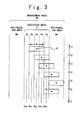
- Fig. 3 is a diagram to explain the reflector detecting and managing method in case where the detected sub-areas of the reflector managed based on the center position P and the width W change with time.
- the time axis is set to the downward direction in the figure.
- the peripheral area is composed of three sub-areas.
- the center position P changes from the center position Dcc of the sub-area Dc to the center position Ddc to the center position Dec.
- the CPU 51 sets "1" to bits of the memory 56 corresponding to the sub-areas Db, Dc and Dd. Also, at the time t2, the CPU 51 sets "1" to a bit of the memory 56 corresponding to the sub-area De and resets the bit corresponding to the sub-area Db to "0". At the time t3, the CPU 51 sets "1" to a bit of the memory 56 corresponding to the left sub-area of the peripheral area Me and resets the bit corresponding to the sub-area Dc to "0".
- the center position P goes out of the detection area D and at time t5, the whole reflector goes out of the detection area D.
- the CPU 51 sets "1" to a bit of the memory 56 corresponding to the center sub-area of the peripheral area Me and resets the bit corresponding to the sub-area Dd to "0".
- this reflector is regarded to exist in the peripheral area Me, and is managed for a predetermined time.
- the CPU 51 sets "1" to a bit of the memory 56 corresponding to the right sub-area of the peripheral area Me and resets the bit corresponding to the sub-area De to "0".
- the CPU 51 sets "1" to a bit of the memory 56 corresponding to the sub-area De of the detection area Me and resets the bit corresponding to the right sub-area of the peripheral area Me to "0".
- the widths of the peripheral areas Ma and Me which are provided for both sides of the detection area D may be previously set to a value of the width of a road lane or the width of the vehicle. Or, the widths of the peripheral areas Ma and Me may be dynamically set to the value which is equal to the width of the reflector which has been detected in the detection area D.
- Fig. 4 is a diagram to explain another reflector detecting and managing method in the case where the movement of the reflector is made in a reverse direction to that of Fig. 3. That is, at first, a part of the reflector is detected only in the sub-area De at time t1. In this case, the center position P is detected and managed to be equal to the center position Dec of this sub-area De. Also, the width W is detected and managed to be equal to the width of this sub-area De. Subsequently, at time t2, even if the reflector goes out of the detection area D once during this management, the reflector is regarded to exist in the peripheral area and is managed for the predetermined time period. When returning to the detection area D at the time t3 before the above predetermined time elapses, the reflector is determined to be the reflector having the width already detected. In this case, only the center position is updated to the lateral direction.
- the width W increases from the width of the sub-area De to the width of the summation of sub-areas De and Dd.
- the center position P and the width W are updated to a new center position and a new width.
- the center position of the reflector further moves to the direction of the center of the detection area D, so that the width W increases to the summation of the three continuous sub-areas De, Dd and Dc.
- the width is updated to a new increased width together with the center position to the lateral direction.
- the width W does not increase.
- only the center position of the reflector to the lateral direction is updated by a new value.
- the width of the reflector already detected is updated to a new value only when the width of the reflector is increased more than the managed value.
- the description of the bit setting operation by the CPU 51 is omitted. However, the operation is performed similarly to that shown in Fig. 3.
- the detection operation is performed based on whether the reflection wave having a reception level higher than the predetermined threshold value is detected in units of sub-areas of the detection area D.
- the center position of the reflector and the width of the reflector are detected and managed as numerical values.
- a weighting and averaging operation in azimuth angle may be used based on the reception level of the reflection wave. That is, the weighting and averaging operation in azimuth angle of the centerline of each fan-shaped sub-area can be used can be used.
- the azimuth angles of the centerlines of respective fan-shaped sub-areas are ⁇ a, ⁇ b, ⁇ c, ⁇ d, and ⁇ e
- the reception levels of the reflection waves which are received in the respective sub-areas are La, Lb, Lc, Ld, and Le.
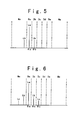
- Fig. 5 shows a case where the reception levels Lb and La of the reflection waves increase monotonously from the sub-area Db of the detection area D to the direction of the sub-area Da thereof.
- the center position ⁇ of the reflector to the lateral direction is calculated using the above-mentioned weighting and averaging operation, the center position is calculated to be an intermediate value between the azimuth angles of ⁇ a and ⁇ b.
- the actual center position of the reflector exists in the sub-area Da or the peripheral area Ma.
- an imaginary reception level Lb' of the reflection wave is supplemented at a symmetrical position of the azimuth angle having the reception level Lb with respect to the azimuth angle having the maximum level La, as shown by the dotted line outside the detection area D.
- a center position ⁇ of the reflector (or azimuth angle ⁇ a) is determined to be in the center Dac of the sub-area Da.
- the width W of the reflector is detected over three sub-areas where the reception levels higher than the predetermined threshold value, including the imaginary reception level are present. These values are managed for the management area Ma which including the peripheral area Ma.
- the reception levels of the reflection waves change with movement of the reflector into the state shown in Fig. 6. That is, the reception levels increase monotonously in order of Lc, Lb, and La to the direction of the peripheral area, as illustrated in Fig. 6.
- two imaginary reception levels Lb and Lc of the reflection waves are supplemented at the symmetrical positions with respect to the maximum reception level La of the reflection wave, as shown by the dotted lines outside the detection area D.
- the center position ⁇ of the reflector does not change.
- the width over five sub-areas is detected, and the width is updated based on this new value.
- the determination of whether the reception levels of the reflection waves increase monotonously to the direction of the peripheral area is performed by comparing the reception levels over all the sub-areas where the reflection waves are detected.
- the determination may be performed to some having higher ones of the reception levels which are detected to be higher than the predetermined threshold value, instead that the comparing operation is performed to all the sub-areas where reflection waves are detected.
- the comparing operation may be performed by a simple comparing operation or by the weighting and comparing operation in which suitable coefficients are multiplied with the reception levels.
- the center position and width of the reflector are detected and managed. However, it is possible to detect and manage only one of the center position and width of the reflector.
- the transmission antenna and the reception antenna are formed as a defocus parabolic multi-beam antenna, which is composed of a common parabolic reflecting mirror and a plane array antenna as a primary emitter arranged in the neighborhood of the focus of this reflecting mirror.
- the radar apparatus may be formed to have the structure, in which a beam is radiated over the whole detection area from a single transmission antenna to have substantially uniform level, and the reflection waves may be received by a plurality of reception antennas having a narrow directivity to cover the corresponding sub-area.
- the radar apparatus may be formed to have the structure, in which a beam is radiated from the transmission antenna having the narrow directivity to each sub-area, and the reflection waves are received by a single transmission antenna having a wide directivity.
- FM radar apparatus which radiates a frequency modulated wave
- AM radar apparatus which radiates an amplitude modulated wave and receives the reflection wave
- pulse radar apparatus which radiates a pulse electromagnetic wave and receives the reflection wave, and which detects a distance to the reflector from the time difference from the radiation to the reception, instead of such a frequency modulated wave.
- the example is described, in which a millimeter wave band electromagnetic wave is radiated and the reflection wave is received.
- the radar apparatus is possible to have the structure in which the electromagnetic wave having another frequency such as a microwave band or a laser beam and another suitable wave such as supersonic wave are radiated and the reflection wave is received so that the distance to the reflector and an azimuth angle are detected.
- the radar apparatus installed on a vehicle of the present invention has the advantage in which because the position or width of the reflector is managed based on the reception information of the reflection wave from the reflector, the detection of the object is possible in the area which is wider than the actual detection area.
- the radar apparatus installed on a vehicle of the present invention is used as the radar apparatus for tracking a preceding vehicle, there is an advantage in that lost of the preceding vehicle in the steep corner is made minimum, and the stable tracking drive becomes possible.
- a radar apparatus installed on a vehicle includes a transmission section (10, 20, 30), a reception section (10, 40) and a processing section (50).
- the transmission section includes at least a transmission antenna, and emits transmission wave toward a detection area in a front of the vehicle.
- the transmission wave is reflected by a reflector to produce reflection wave, and the detection area includes a plurality of sub-areas.
- the reception section includes at least a reception antenna, and receives and detects the reflection wave.
- the processing unit detects a reflector indication data indicative of a reflector attribute based on the detecting result by the reception section, and then determines whether there is the reflector in the detection area, based on the reflector indication data.
- the processing section manages the reflector indication data over a management area which is wider than the detection area.
Landscapes
- Engineering & Computer Science (AREA)
- Radar, Positioning & Navigation (AREA)
- Remote Sensing (AREA)
- Physics & Mathematics (AREA)
- Electromagnetism (AREA)
- Computer Networks & Wireless Communication (AREA)
- General Physics & Mathematics (AREA)
- Radar Systems Or Details Thereof (AREA)
- Optical Radar Systems And Details Thereof (AREA)
- Measurement Of Velocity Or Position Using Acoustic Or Ultrasonic Waves (AREA)
Applications Claiming Priority (2)
| Application Number | Priority Date | Filing Date | Title |
|---|---|---|---|
| JP05014398A JP3942722B2 (ja) | 1998-02-16 | 1998-02-16 | 車載レーダ装置 |
| JP5014398 | 1998-02-16 |
Publications (2)
| Publication Number | Publication Date |
|---|---|
| EP0936473A1 true EP0936473A1 (fr) | 1999-08-18 |
| EP0936473B1 EP0936473B1 (fr) | 2002-07-10 |
Family
ID=12850954
Family Applications (1)
| Application Number | Title | Priority Date | Filing Date |
|---|---|---|---|
| EP99103066A Expired - Lifetime EP0936473B1 (fr) | 1998-02-16 | 1999-02-16 | Dispositif radar installé sur un véhicule pour la gestion d'informations de réflecteurs |
Country Status (4)
| Country | Link |
|---|---|
| US (1) | US6008751A (fr) |
| EP (1) | EP0936473B1 (fr) |
| JP (1) | JP3942722B2 (fr) |
| DE (1) | DE69902064T2 (fr) |
Cited By (3)
| Publication number | Priority date | Publication date | Assignee | Title |
|---|---|---|---|---|
| WO2002075355A1 (fr) * | 2001-03-15 | 2002-09-26 | Fujitsu Ten Limited | Procede de traitement de signaux pour radar a balayage |
| WO2002075351A1 (fr) * | 2001-03-19 | 2002-09-26 | Fujitsu Ten Limited | Détection d'objet stationnaire sur route au moyen d'un radar |
| EP1519204A1 (fr) * | 2003-09-29 | 2005-03-30 | Volkswagen Aktiengesellschaft | Radar multistatique pour véhicule |
Families Citing this family (19)
| Publication number | Priority date | Publication date | Assignee | Title |
|---|---|---|---|---|
| JP3750102B2 (ja) | 1999-11-24 | 2006-03-01 | 富士通テン株式会社 | 車載レーダ装置 |
| JP4719996B2 (ja) * | 2001-03-30 | 2011-07-06 | 日産自動車株式会社 | 物体検知装置 |
| US6661370B2 (en) | 2001-12-11 | 2003-12-09 | Fujitsu Ten Limited | Radar data processing apparatus and data processing method |
| JP3991793B2 (ja) | 2002-07-05 | 2007-10-17 | 株式会社村田製作所 | レーダ |
| DE10233523A1 (de) * | 2002-07-23 | 2004-02-05 | S.M.S., Smart Microwave Sensors Gmbh | Sensor zum Aussenden und Empfangen von elektromagnetischen Signalen |
| JP2005156337A (ja) * | 2003-11-26 | 2005-06-16 | Hitachi Ltd | 車載用レーダ装置 |
| JP2006209687A (ja) * | 2005-01-31 | 2006-08-10 | Sony Corp | データ処理回路 |
| JP4163695B2 (ja) * | 2005-03-16 | 2008-10-08 | 本田技研工業株式会社 | 先行車認識装置 |
| DE102005044884A1 (de) * | 2005-09-20 | 2007-03-29 | Siemens Ag | Radarsystem |
| JP4684876B2 (ja) | 2005-12-14 | 2011-05-18 | 富士通テン株式会社 | レーダー装置及びレーダー装置の対象物検出方法 |
| JP4887842B2 (ja) * | 2006-03-09 | 2012-02-29 | オムロン株式会社 | レーダ装置 |
| JP4769684B2 (ja) * | 2006-10-12 | 2011-09-07 | 株式会社デンソーアイティーラボラトリ | 電子走査式レーダ装置 |
| JP4994852B2 (ja) * | 2007-01-15 | 2012-08-08 | 三菱電機株式会社 | 車載用レーダ装置 |
| JP5380788B2 (ja) | 2007-05-30 | 2014-01-08 | トヨタ自動車株式会社 | 物体検出装置、及び車両用制御装置 |
| US7973700B2 (en) * | 2008-01-31 | 2011-07-05 | Denso International America, Inc. | Dual transmitting antenna system |
| JP4823282B2 (ja) * | 2008-09-01 | 2011-11-24 | 富士通テン株式会社 | 周辺監視センサ |
| US9550493B2 (en) * | 2014-09-01 | 2017-01-24 | Komatsu Ltd. | Transporter vehicle and transporter vehicle control method |
| US11400956B2 (en) | 2017-02-23 | 2022-08-02 | Richard Anthony Bishel | Vehicle guidance system |
| US12162512B2 (en) * | 2021-09-29 | 2024-12-10 | Ford Global Technologies, Llc | Systems and methods for onboard analysis of sensor data for sensor fusion |
Citations (6)
| Publication number | Priority date | Publication date | Assignee | Title |
|---|---|---|---|---|
| US4122450A (en) * | 1975-06-16 | 1978-10-24 | Hughes Aircraft Company | Infinite ratio clutter detecting system |
| US4357607A (en) * | 1979-02-09 | 1982-11-02 | Hollandse Signaalapparaten B.V. | Video extractor |
| EP0495759A1 (fr) * | 1991-01-17 | 1992-07-22 | SMA SEGNALAMENTO MARITTIMO ED AEREO S.p.A. | Procédé et appareillage pour l'extraction d'une carte des obstacles à partir du signal d'un détecteur radar à balayage avec transmission impulsionnelle, pour véhicule |
| US5467284A (en) * | 1993-05-24 | 1995-11-14 | Mazda Motor Corporation | Obstacle detection system for motor vehicle |
| US5668739A (en) * | 1994-09-02 | 1997-09-16 | Caterpillar Inc. | System and method for tracking objects using a detection system |
| WO1998000728A1 (fr) * | 1996-06-28 | 1998-01-08 | Ford Motor Company Limited | Systeme avertisseur de collision pour vehicule routier a moteur |
Family Cites Families (6)
| Publication number | Priority date | Publication date | Assignee | Title |
|---|---|---|---|---|
| US36095A (en) * | 1862-08-05 | Improvement in funnel pleasures | ||
| JP2567332B2 (ja) * | 1993-02-17 | 1996-12-25 | 本田技研工業株式会社 | 時分割型レーダシステム |
| JP2989428B2 (ja) * | 1993-06-17 | 1999-12-13 | 本田技研工業株式会社 | 時分割型fmレーダシステム |
| JP3256374B2 (ja) * | 1994-05-27 | 2002-02-12 | 本田技研工業株式会社 | マルチビーム・レーダ装置 |
| US5933109A (en) * | 1996-05-02 | 1999-08-03 | Honda Giken Kabushiki Kaisha | Multibeam radar system |
| JP3012805B2 (ja) * | 1996-05-09 | 2000-02-28 | 本田技研工業株式会社 | Fmレーダ装置 |
-
1998
- 1998-02-16 JP JP05014398A patent/JP3942722B2/ja not_active Expired - Fee Related
-
1999
- 1999-02-16 DE DE69902064T patent/DE69902064T2/de not_active Expired - Fee Related
- 1999-02-16 US US09/250,375 patent/US6008751A/en not_active Expired - Lifetime
- 1999-02-16 EP EP99103066A patent/EP0936473B1/fr not_active Expired - Lifetime
Patent Citations (6)
| Publication number | Priority date | Publication date | Assignee | Title |
|---|---|---|---|---|
| US4122450A (en) * | 1975-06-16 | 1978-10-24 | Hughes Aircraft Company | Infinite ratio clutter detecting system |
| US4357607A (en) * | 1979-02-09 | 1982-11-02 | Hollandse Signaalapparaten B.V. | Video extractor |
| EP0495759A1 (fr) * | 1991-01-17 | 1992-07-22 | SMA SEGNALAMENTO MARITTIMO ED AEREO S.p.A. | Procédé et appareillage pour l'extraction d'une carte des obstacles à partir du signal d'un détecteur radar à balayage avec transmission impulsionnelle, pour véhicule |
| US5467284A (en) * | 1993-05-24 | 1995-11-14 | Mazda Motor Corporation | Obstacle detection system for motor vehicle |
| US5668739A (en) * | 1994-09-02 | 1997-09-16 | Caterpillar Inc. | System and method for tracking objects using a detection system |
| WO1998000728A1 (fr) * | 1996-06-28 | 1998-01-08 | Ford Motor Company Limited | Systeme avertisseur de collision pour vehicule routier a moteur |
Cited By (5)
| Publication number | Priority date | Publication date | Assignee | Title |
|---|---|---|---|---|
| WO2002075355A1 (fr) * | 2001-03-15 | 2002-09-26 | Fujitsu Ten Limited | Procede de traitement de signaux pour radar a balayage |
| US6900754B2 (en) | 2001-03-15 | 2005-05-31 | Fujitsu Tem Limited | Signal processing method for use with scanning radar |
| CN100359337C (zh) * | 2001-03-15 | 2008-01-02 | 富士通天株式会社 | 扫描式雷达的信号处理方法 |
| WO2002075351A1 (fr) * | 2001-03-19 | 2002-09-26 | Fujitsu Ten Limited | Détection d'objet stationnaire sur route au moyen d'un radar |
| EP1519204A1 (fr) * | 2003-09-29 | 2005-03-30 | Volkswagen Aktiengesellschaft | Radar multistatique pour véhicule |
Also Published As
| Publication number | Publication date |
|---|---|
| EP0936473B1 (fr) | 2002-07-10 |
| DE69902064T2 (de) | 2002-11-28 |
| JP3942722B2 (ja) | 2007-07-11 |
| JPH11231053A (ja) | 1999-08-27 |
| US6008751A (en) | 1999-12-28 |
| DE69902064D1 (de) | 2002-08-14 |
Similar Documents
| Publication | Publication Date | Title |
|---|---|---|
| US6008751A (en) | Radar apparatus installed on vehicle for managing reflector information | |
| EP0936474B1 (fr) | Dispositif radar installé sur un véhicule automobile pour la détection correcte d'obstacles | |
| EP0859241B1 (fr) | Système de radar à temps partagé | |
| JP2768439B2 (ja) | Fm−cw方式マルチビームレーダー装置 | |
| JP4238375B2 (ja) | レーダ装置 | |
| US5717399A (en) | Radar device for vehicle use | |
| JP2989428B2 (ja) | 時分割型fmレーダシステム | |
| JP3393204B2 (ja) | マルチビームレーダ装置 | |
| US6335700B1 (en) | Radar apparatus for preventing erroneous detection by comparing sensitivities of each combination of transmitting and receiving units | |
| US6940447B2 (en) | Radar device and method for operating a radar device | |
| EP0805360A2 (fr) | Système de radar à faisceaux multiples | |
| EP1239298B1 (fr) | Procédé et radar pour déterminer la distance d'une cible | |
| US11709261B2 (en) | Radar device for vehicle, controlling method of radar device and radar system for vehicle | |
| JP2000258524A (ja) | レーダ装置 | |
| JP2000227473A (ja) | レーダ装置及びレーダ装置の異常検出方法 | |
| US20060109168A1 (en) | Radar | |
| JPH1184001A (ja) | 車載レーダ装置及びこれを用いた車両の自動制御システム | |
| JP2802671B2 (ja) | ミリ波レーダ送受信機 | |
| JP2964947B2 (ja) | 時分割型レーダシステム | |
| JP2750781B2 (ja) | Fmレーダ | |
| JP3357585B2 (ja) | 車載レーダ装置 | |
| JP2875509B2 (ja) | Fmレーダ装置 |
Legal Events
| Date | Code | Title | Description |
|---|---|---|---|
| PUAI | Public reference made under article 153(3) epc to a published international application that has entered the european phase |
Free format text: ORIGINAL CODE: 0009012 |
|
| 17P | Request for examination filed |
Effective date: 19990216 |
|
| AK | Designated contracting states |
Kind code of ref document: A1 Designated state(s): DE FR GB |
|
| AX | Request for extension of the european patent |
Free format text: AL;LT;LV;MK;RO;SI |
|
| AKX | Designation fees paid |
Free format text: DE FR GB |
|
| 17Q | First examination report despatched |
Effective date: 20000914 |
|
| GRAG | Despatch of communication of intention to grant |
Free format text: ORIGINAL CODE: EPIDOS AGRA |
|
| GRAG | Despatch of communication of intention to grant |
Free format text: ORIGINAL CODE: EPIDOS AGRA |
|
| GRAH | Despatch of communication of intention to grant a patent |
Free format text: ORIGINAL CODE: EPIDOS IGRA |
|
| GRAH | Despatch of communication of intention to grant a patent |
Free format text: ORIGINAL CODE: EPIDOS IGRA |
|
| GRAA | (expected) grant |
Free format text: ORIGINAL CODE: 0009210 |
|
| AK | Designated contracting states |
Kind code of ref document: B1 Designated state(s): DE FR GB |
|
| REG | Reference to a national code |
Ref country code: GB Ref legal event code: FG4D |
|
| REF | Corresponds to: |
Ref document number: 69902064 Country of ref document: DE Date of ref document: 20020814 |
|
| ET | Fr: translation filed | ||
| PLBE | No opposition filed within time limit |
Free format text: ORIGINAL CODE: 0009261 |
|
| STAA | Information on the status of an ep patent application or granted ep patent |
Free format text: STATUS: NO OPPOSITION FILED WITHIN TIME LIMIT |
|
| 26N | No opposition filed |
Effective date: 20030411 |
|
| PGFP | Annual fee paid to national office [announced via postgrant information from national office to epo] |
Ref country code: DE Payment date: 20070208 Year of fee payment: 9 |
|
| PGFP | Annual fee paid to national office [announced via postgrant information from national office to epo] |
Ref country code: GB Payment date: 20070214 Year of fee payment: 9 |
|
| PGFP | Annual fee paid to national office [announced via postgrant information from national office to epo] |
Ref country code: FR Payment date: 20070208 Year of fee payment: 9 |
|
| GBPC | Gb: european patent ceased through non-payment of renewal fee |
Effective date: 20080216 |
|
| REG | Reference to a national code |
Ref country code: FR Ref legal event code: ST Effective date: 20081031 |
|
| PG25 | Lapsed in a contracting state [announced via postgrant information from national office to epo] |
Ref country code: DE Free format text: LAPSE BECAUSE OF NON-PAYMENT OF DUE FEES Effective date: 20080902 |
|
| PG25 | Lapsed in a contracting state [announced via postgrant information from national office to epo] |
Ref country code: FR Free format text: LAPSE BECAUSE OF NON-PAYMENT OF DUE FEES Effective date: 20080229 |
|
| PG25 | Lapsed in a contracting state [announced via postgrant information from national office to epo] |
Ref country code: GB Free format text: LAPSE BECAUSE OF NON-PAYMENT OF DUE FEES Effective date: 20080216 |