EP1519204A1 - Radar multistatique pour véhicule - Google Patents
Radar multistatique pour véhicule Download PDFInfo
- Publication number
- EP1519204A1 EP1519204A1 EP04022028A EP04022028A EP1519204A1 EP 1519204 A1 EP1519204 A1 EP 1519204A1 EP 04022028 A EP04022028 A EP 04022028A EP 04022028 A EP04022028 A EP 04022028A EP 1519204 A1 EP1519204 A1 EP 1519204A1
- Authority
- EP
- European Patent Office
- Prior art keywords
- signal
- measuring device
- angle
- beam direction
- receiving
- Prior art date
- Legal status (The legal status is an assumption and is not a legal conclusion. Google has not performed a legal analysis and makes no representation as to the accuracy of the status listed.)
- Granted
Links
- 230000005540 biological transmission Effects 0.000 claims abstract description 58
- 238000000034 method Methods 0.000 claims abstract description 13
- 238000011156 evaluation Methods 0.000 claims description 12
- 230000003287 optical effect Effects 0.000 claims description 10
- 239000002131 composite material Substances 0.000 claims description 5
- 230000000007 visual effect Effects 0.000 claims 1
- 108010076504 Protein Sorting Signals Proteins 0.000 description 14
- 238000002955 isolation Methods 0.000 description 7
- 238000001228 spectrum Methods 0.000 description 7
- 238000010586 diagram Methods 0.000 description 5
- 238000005259 measurement Methods 0.000 description 2
- 238000000926 separation method Methods 0.000 description 2
- 230000002123 temporal effect Effects 0.000 description 2
- 238000002485 combustion reaction Methods 0.000 description 1
- 238000001514 detection method Methods 0.000 description 1
- 238000005070 sampling Methods 0.000 description 1
Images




Classifications
-
- G—PHYSICS
- G01—MEASURING; TESTING
- G01S—RADIO DIRECTION-FINDING; RADIO NAVIGATION; DETERMINING DISTANCE OR VELOCITY BY USE OF RADIO WAVES; LOCATING OR PRESENCE-DETECTING BY USE OF THE REFLECTION OR RERADIATION OF RADIO WAVES; ANALOGOUS ARRANGEMENTS USING OTHER WAVES
- G01S13/00—Systems using the reflection or reradiation of radio waves, e.g. radar systems; Analogous systems using reflection or reradiation of waves whose nature or wavelength is irrelevant or unspecified
- G01S13/88—Radar or analogous systems specially adapted for specific applications
- G01S13/93—Radar or analogous systems specially adapted for specific applications for anti-collision purposes
- G01S13/931—Radar or analogous systems specially adapted for specific applications for anti-collision purposes of land vehicles
-
- G—PHYSICS
- G01—MEASURING; TESTING
- G01S—RADIO DIRECTION-FINDING; RADIO NAVIGATION; DETERMINING DISTANCE OR VELOCITY BY USE OF RADIO WAVES; LOCATING OR PRESENCE-DETECTING BY USE OF THE REFLECTION OR RERADIATION OF RADIO WAVES; ANALOGOUS ARRANGEMENTS USING OTHER WAVES
- G01S13/00—Systems using the reflection or reradiation of radio waves, e.g. radar systems; Analogous systems using reflection or reradiation of waves whose nature or wavelength is irrelevant or unspecified
- G01S13/003—Bistatic radar systems; Multistatic radar systems
-
- G—PHYSICS
- G01—MEASURING; TESTING
- G01S—RADIO DIRECTION-FINDING; RADIO NAVIGATION; DETERMINING DISTANCE OR VELOCITY BY USE OF RADIO WAVES; LOCATING OR PRESENCE-DETECTING BY USE OF THE REFLECTION OR RERADIATION OF RADIO WAVES; ANALOGOUS ARRANGEMENTS USING OTHER WAVES
- G01S13/00—Systems using the reflection or reradiation of radio waves, e.g. radar systems; Analogous systems using reflection or reradiation of waves whose nature or wavelength is irrelevant or unspecified
- G01S13/02—Systems using reflection of radio waves, e.g. primary radar systems; Analogous systems
- G01S13/06—Systems determining position data of a target
- G01S13/08—Systems for measuring distance only
- G01S13/32—Systems for measuring distance only using transmission of continuous waves, whether amplitude-, frequency-, or phase-modulated, or unmodulated
- G01S13/34—Systems for measuring distance only using transmission of continuous waves, whether amplitude-, frequency-, or phase-modulated, or unmodulated using transmission of continuous, frequency-modulated waves while heterodyning the received signal, or a signal derived therefrom, with a locally-generated signal related to the contemporaneously transmitted signal
- G01S13/348—Systems for measuring distance only using transmission of continuous waves, whether amplitude-, frequency-, or phase-modulated, or unmodulated using transmission of continuous, frequency-modulated waves while heterodyning the received signal, or a signal derived therefrom, with a locally-generated signal related to the contemporaneously transmitted signal using square or rectangular modulation, e.g. diplex radar for ranging over short distances
-
- G—PHYSICS
- G01—MEASURING; TESTING
- G01S—RADIO DIRECTION-FINDING; RADIO NAVIGATION; DETERMINING DISTANCE OR VELOCITY BY USE OF RADIO WAVES; LOCATING OR PRESENCE-DETECTING BY USE OF THE REFLECTION OR RERADIATION OF RADIO WAVES; ANALOGOUS ARRANGEMENTS USING OTHER WAVES
- G01S13/00—Systems using the reflection or reradiation of radio waves, e.g. radar systems; Analogous systems using reflection or reradiation of waves whose nature or wavelength is irrelevant or unspecified
- G01S13/02—Systems using reflection of radio waves, e.g. primary radar systems; Analogous systems
- G01S13/06—Systems determining position data of a target
- G01S13/42—Simultaneous measurement of distance and other co-ordinates
-
- G—PHYSICS
- G01—MEASURING; TESTING
- G01S—RADIO DIRECTION-FINDING; RADIO NAVIGATION; DETERMINING DISTANCE OR VELOCITY BY USE OF RADIO WAVES; LOCATING OR PRESENCE-DETECTING BY USE OF THE REFLECTION OR RERADIATION OF RADIO WAVES; ANALOGOUS ARRANGEMENTS USING OTHER WAVES
- G01S13/00—Systems using the reflection or reradiation of radio waves, e.g. radar systems; Analogous systems using reflection or reradiation of waves whose nature or wavelength is irrelevant or unspecified
- G01S13/88—Radar or analogous systems specially adapted for specific applications
- G01S13/93—Radar or analogous systems specially adapted for specific applications for anti-collision purposes
- G01S13/931—Radar or analogous systems specially adapted for specific applications for anti-collision purposes of land vehicles
- G01S2013/9323—Alternative operation using light waves
-
- G—PHYSICS
- G01—MEASURING; TESTING
- G01S—RADIO DIRECTION-FINDING; RADIO NAVIGATION; DETERMINING DISTANCE OR VELOCITY BY USE OF RADIO WAVES; LOCATING OR PRESENCE-DETECTING BY USE OF THE REFLECTION OR RERADIATION OF RADIO WAVES; ANALOGOUS ARRANGEMENTS USING OTHER WAVES
- G01S13/00—Systems using the reflection or reradiation of radio waves, e.g. radar systems; Analogous systems using reflection or reradiation of waves whose nature or wavelength is irrelevant or unspecified
- G01S13/88—Radar or analogous systems specially adapted for specific applications
- G01S13/93—Radar or analogous systems specially adapted for specific applications for anti-collision purposes
- G01S13/931—Radar or analogous systems specially adapted for specific applications for anti-collision purposes of land vehicles
- G01S2013/9327—Sensor installation details
- G01S2013/93274—Sensor installation details on the side of the vehicles
-
- G—PHYSICS
- G01—MEASURING; TESTING
- G01S—RADIO DIRECTION-FINDING; RADIO NAVIGATION; DETERMINING DISTANCE OR VELOCITY BY USE OF RADIO WAVES; LOCATING OR PRESENCE-DETECTING BY USE OF THE REFLECTION OR RERADIATION OF RADIO WAVES; ANALOGOUS ARRANGEMENTS USING OTHER WAVES
- G01S13/00—Systems using the reflection or reradiation of radio waves, e.g. radar systems; Analogous systems using reflection or reradiation of waves whose nature or wavelength is irrelevant or unspecified
- G01S13/88—Radar or analogous systems specially adapted for specific applications
- G01S13/93—Radar or analogous systems specially adapted for specific applications for anti-collision purposes
- G01S13/931—Radar or analogous systems specially adapted for specific applications for anti-collision purposes of land vehicles
- G01S2013/9327—Sensor installation details
- G01S2013/93275—Sensor installation details in the bumper area
Definitions
- the invention relates to a measuring device, in particular a measuring device for a Motor vehicle for measuring an angle between a measuring device and an object.
- DE 195 43 813 A1 discloses a three-beam motor vehicle radar system, wherein at an angle a wavefront hits a lens of a lens antenna.
- a wavefront hits a lens of a lens antenna.
- receiving elements In the Focal plane of this lens, indicated by the distance, are three receiving elements, respectively with a lateral distance from each other, arranged for the reception of radar signals.
- mixers In three envisaged mixers is in the respectively supplied by an oscillator frequency in mixed with the receiving elements generated high frequency signal. Be in a detector from the mixed signals in which the phase information is contained, detected target objects. By means of a phase comparator connected thereto, the phase difference and therefrom then determined in a computer, the angle to the target object. The value of this angle is at the output of the computer via a suitable output channel further stages of the Systems supplied.
- WO01 / 26183 discloses a multi-beam radar sensor having at least two transmitting and Receive patches on a carrier with associated polyrods and / or with a dielectric lens, wherein the radar sensor is constructed monostatically and configured that the transmitting or receiving beams with respect to a center plane of the radar sensor have asymmetrical beam paths.
- DE 100 50 278 A1 discloses the determination of a distance and a Relative speed of at least one remote object from an observation point with Help of electromagnetic signals emitted from the observation point in the form of alternately transmitted signal portions of a first frequency and a second Frequency, which are received and evaluated after reflection on the object, where the signal sections of the two frequencies during a measurement interval by one Frequency step be sent shifted.
- CW radar method Continuous Wave Radarvon or continuous wave radar method
- a transmission signal from at least four consecutive blocks, each with different gradients consists.
- a distance-relative velocity diagram the first Intersections of all lines from two blocks calculated from all found frequency positions. In order to validate these intersections, they are checked to see if they are Fourier spectrum of a third block a peak exists at a frequency position whose associated straight line in the distance-relative velocity diagram a surrounding area of the intersection intersects.
- intersections become a second one Condition subjected, whether in the Fourier spectrum of a fourth block, a peak at one Frequency position exists whose associated straight line in the distance-relative velocity diagram cuts a surrounding area of the intersection.
- the intersections will be considered valid if they meet both conditions.
- DE 42 44 608 C2 discloses a radar method for measuring distances and Relative speeds between a vehicle and obstacles in front of it, with emission of continuous transmission signals, while transmitting the continuous Transmission signals simultaneous reception at the obstacles of reflected signals, mixing the reflected signals with the continuous transmission signals for obtaining in-phase and Quadrature signals and processing these signals to output signals for the distances and relative speeds of the obstacles, wherein the continuous transmission signals in Frequency constant stages of constant time length decomposed without temporal distance from each other and at each frequency constant level of the reflected received signal Complex sample detected and the transmission signal of the same frequency constant stage is mixed.
- DE 100 25 844 A1 discloses a serving for the emission of a pulse-shaped transmission signal Transmitting unit, which is driven clocked with a first drive signal, and one for Detection of the resulting reflection signal serving receiving unit, which with a clocked driven a second drive signal to the reflection signal to to sample certain sampling times.
- the second drive signal is compared with the first drive signal phase shifted such that the distance deviation between the distance to the target object determined by the transit time measurement and the actual distance Distance to the target object becomes minimal.
- T2 is a Doppler radar device for a vehicle for displaying a Distance between the vehicle and an obstacle known.
- Beam direction of a measuring device is in particular a Boresight. Beam direction of a measuring device according to the invention in particular, a direction orthogonal to a plane through the first and the second Receiving device is.
- the invention may comprise a beam shape of a lobe, in particular it is provided that a sufficient part of the transmission power hits the object.
- a first by means of the first mixer Mixed signal chanbar is (moreover) by means of the second mixer a second mixing signal chanbar.
- the measuring device has a Evaluation device for determining the angle between the beam direction of Measuring device and the object in dependence of the first and the second mixed signal.
- the measuring device is not more than a radiating device. In a further advantageous embodiment of the invention, the Measuring device no more than two receiving devices.
- the emitting device and the Receiving devices integrated in a housing.
- the measuring device has three, in particular not more than three, receiving devices.
- a first by means of the measuring device Angle between the beam direction of the measuring device and the object in a first plane and a second angle between the beam direction of the measuring device and the object in measurable at a second level, the first level and the second level advantageously are substantially orthogonal.
- the emitting device and the Receiving device per one antenna.
- the emitting device and a receiving device can also be implemented by means of a common antenna.
- the emitting device is an optical element, in particular a laser.
- the receiving device is in a further embodiment of the Invention, a photosensitive element, in particular a photodiode.
- the measuring device is in a Driver assistance system used, the driver assistance system to a valuer for Generation of warning information as a function of the angle between the beam direction of Measuring device and the object and depending on the distance between the Measuring device and the object has.
- the warning information by means of Evaluator also depending on the speed difference between the measuring device and the object can be generated.
- the warning information by means of Evaluator also generated depending on a state of a driving direction indicator.
- the angle between the beam direction of Measuring device and the object in response to the first mixed signal and the second Mixed signal determined.
- the angle between the Beam direction of the measuring device and the object as a function of the difference of the phase of the first mixed signal and the phase of the second mixed signal.
- a distance between the Measuring device and the object in dependence of the first mixing signal and / or the second Mixed signal determined.
- a speed difference between the measuring device and the object is a speed difference between the measuring device and the object as a function of the first mixed signal and / or the second mixed signal.
- an optical, acoustic and / or Haptic warning signal as a function of the angle between the beam direction of Measuring device and the object and depending on the distance between the Measuring device and the object generated.
- the optical, acoustic and / or haptic warning signal also depending on the speed difference between the Measuring device and the object generated.
- the optical, acoustic and / or Haptic warning signal also depending on a state of a driving direction indicator generated.
- Motor vehicle in the sense of the invention is in particular an individual on the road usable land vehicle.
- Motor vehicles according to the invention are not in particular Land vehicles with internal combustion engine limited.
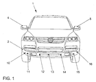
- Fig. 1, Fig. 2 and Fig. 3 show a motor vehicle 1 in an exemplary embodiment.
- Fig. 1 shows while a front view of the motor vehicle 1
- Fig. 2 shows a side view of the Motor vehicle 1
- Fig. 3 shows a plan view of the motor vehicle.
- the motor vehicle 1 has a front bumper 2 and a rear bumper 3.
- the front Bumper 2 has an exemplary embodiment angle, distance and / or Speed sensors 10, 11, 12, 13, 14, 15, 16 for measuring an angle between a beam direction of an angular, distance and / or velocity sensor 10, 11, 12, 13, 14, 15, 16 and an object or obstacle 20, such as another motor vehicle, and optionally the distance R between the motor vehicle 1 and the object or obstacle 20 and / or for measuring a speed difference v between the motor vehicle 1 and the object or obstacle 20, wherein the speed difference v is the difference of Speed vH of the obstacle 20 and the speed vF of the motor vehicle 1 is.
- angle and / or speed sensors 10 11, 12, 13, 14, 15, 16 more or less angle, distance and / or Speed sensors may be arranged on the bumper 2. It can alternatively or In addition, angle, distance and / or speed sensors on the rear Bumpers 3, on side mirrors 4, 5, on side doors 6, 7 and / or on a tailgate 8 be arranged. The angle, distance and / or speed sensors can be used in be aligned in different directions and / or in different heights.
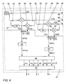
- Fig. 4 shows a radar device 30, e.g. as angle, distance and / or Speed sensor 10, 11, 12, 13, 14, 15, 16 is usable.
- the radar device 30 has a radar sensor 40 and an evaluation device 41.
- the radar device 30 comprises an oscillator or a signal generator 31 for generating a transmission signal s (t), a transmitting antenna 35 for emitting the transmission signal s (t) and a receiving antenna 36 for receiving a reflection signal r1 (t) reflected by an object such as the obstacle 20 of the radiated transmission signal s (t).
- t denotes the time.
- the transmission signal s (t) generated by means of the signal generator 31 comprises by way of example Embodiment at least two signal sequence sections, a first signal section sequence and a second signal sequence, with at least two temporally alternating ones Signal sections, wherein the at least two signal sections of a signal section sequence differ in their frequency by one difference frequency, and wherein the difference frequency the first signal section sequence of the difference frequency of the second signal section sequence, in particular by at least 5%, advantageously by at least 10%, is different.
- Fig. 5 One Embodiment of such a transmission signal is shown in Fig. 5 in a frequency-time diagram shown.
- A1, A2, A3,... Designate the signal sections of a first signal section sequence A (t) and B1, B2, B3,... The signal sections of a second signal section sequence B (t). Such signal sections are also referred to as chirps.
- the durations T burst for the signal sections A1, A2, A3,... And B1, B2, B3,... Are the same length.
- the durations T Burst of the signal sections A1, A2, A3,... Are shown in FIG. 4 by a solid line and the durations T Burst of the signal sections B1, B2, B3,... By a dashed line.
- the individual signal sections A1, A2, A3,... Of the first signal section sequence A (t) differ in their frequency or their carrier frequency f T (t) by a difference frequency f Hub, A / (N-1), where f Hub, A is the difference between the carrier frequency of the first signal section A1 of the first signal section sequence A (t) and the carrier frequency of the Nth signal section of the first signal section sequence A (t) and N is the number of signal sections A1, A2, A3, first signal section sequence A (t).
- the difference frequency f Hub, B / (N-1), f Hub, B is the difference between the carrier frequency of the first signal section B1 of the second signal section sequence B (t) and the carrier frequency of the Nth signal section of the second signal section sequence B (t) and N is also the number of signal sections B1, B2, B3, ... the first signal section sequence B (t).
- the difference frequency f stroke, A / (N-1) and the first signal section sequence A (t) in particular by at least 5%, advantageously by at least 10%, different from the difference frequency f hub, B / (N-1) of the second signal sequence B (t).
- a frequency offset f Shift between the signal section A1 of the first signal section sequence A (t) and the signal section B1 of the second signal section sequence B (t) can be provided.
- the first signal section sequence A (t) results and the second signal sequence B (t) where f TA1 denotes the carrier frequency of the signal section A1 and rect the rectangular function.
- Et al can be provided Transmission signal according to DE 100 50 278 A1 ereddlingen.
- the transmission signal s (t) is connected to a mixer 38 by means of a galvanic isolation 32 Mixing of the transmission signal s (t) and the reflection signal r1 (t) supplied.
- the mixer 38 gives an in-phase signal I1 (t) off.
- the transmission signal s (t) is also a means of a further galvanic isolation 33 a Phase shifter 37 supplied by means of which the phase of the transmission signal s (t) based on the Carrier frequency is shifted by 90 ° so ⁇ / 2.
- the phase-shifted transmission signal is a mixer 39 for mixing the phase-shifted transmission signal and the Reflection signal r1 (t) supplied to the mixer 39 by means of a galvanic isolation 34th is forwarded.
- the mixer 39 outputs a quadrature signal Q1 (t). Inphase signal I1 (t) and the quadrature signal Q1 (t) are mixed signals in the sense of the claims.
- the radar device 30 has a multiplier 42, by means of which the quadrature signal Q1 (t) is multiplied by the complex number j to jQ1 (t). I1 (t) and I1Q (t) become one complex mixing signal m1 (t) added.
- the complex mixed signal m1 (t) is also on Mixed signal in the sense of the claims.
- the radar device 30 also has a Frequency analyzer 43, by means of which - e.g. through an FFT - a spectrum M1 ( ⁇ ) of the complex mixing signal m1 (t) over the frequency ⁇ is formed.
- the radar device 30 also has a receiving antenna 56 for receiving one of an object such as the obstacle 20 reflected reflection signal r2 (t) of the radiated Transmission signal s (t) on.
- the transmission signal s (t) is by means of a galvanic isolation 52 a Mixer 58 for mixing the transmission signal s (t) and the reflection signal r2 (t) supplied. Of the Mixer 58 outputs an in-phase signal I2 (t).
- the transmission signal s (t) is also a means of a further galvanic isolation 53 a Phase shifter 57 supplied by means of which the phase of the transmission signal s (t) based on the Carrier frequency is shifted by 90 ° so ⁇ / 2.
- the phase-shifted transmission signal is a mixer 59 for mixing the phase-shifted transmission signal and the Reflection signal r2 (t) supplied to the mixer 59 by means of a galvanic isolation 54 is forwarded.
- the mixer 59 outputs a quadrature signal Q2 (t). Inphase signal I2 (t) and the quadrature signal Q2 (t) are mixed signals in the sense of the claims.
- the radar device 30 has a multiplier 62, by means of which the quadrature signal Q2 (t) is multiplied by the complex number j to jQ2 (t). I2 (t) and j2Q (t) become one complex mixed signal m2 (t) added.
- the complex mixed signal m2 (t) is also a Mixed signal in the sense of the claims.
- the radar device 30 also has a Frequency analyzer 63, by means of which - e.g. through an FFT - a spectrum M2 ( ⁇ ) of the complex mixed signal m2 (t) over the frequency ⁇ is formed.
- the processing of the individual signal sequences A (t) and B (t) is advantageously carried out separately by temporal separation, so that by means of the mixers 38 and 39 or 58 and 59, the first signal section sequence A (t) with a reflected from the object 20 portion the first signal section sequence A (t) (the reflection signal r1 (t) or r2 (t)) to a first mixed signal l1 A (t), Q1 A (t) and m1 A (t) and l2 A (t) , Q2 A (t) or m2 A (t) and the second signal sequence B (t) with a reflected from the object 20 portion of the second signal section sequence B (t) (the reflection signal r1 (t) or r2 (t)) a second mixing signal l1 B (t), Q1 B (t) and B m1 (t) and I 2 B (t), Q2 B (t) and m2 B (t) is mixed.
- the dominant frequency ⁇ 1 A of the complex mixed signal m1 A (t) and the dominant frequency ⁇ 2 A of the complex complex signal m2 A (t) (ie with respect to the first signal sequence A (t)) and the dominant frequency ⁇ 1 B of the complex complex signal m1 B (t) and the dominant frequency ⁇ 2 B of the complex complex signal m2 B (t) (ie with respect to the second signal sequence B (t)) determined.
- ⁇ 1 A 2 ⁇ ⁇ f T c ⁇ ( N -1) ⁇ T burst - 2 R c ⁇ f Hub
- a ⁇ 2 A 2 ⁇ ⁇ f T c ⁇ ( N -1) ⁇ T burst - 2 R c ⁇ f Hub
- a ⁇ 1 B 2 ⁇ ⁇ f T c ⁇ ( N -1) ⁇ T burst - 2 R c ⁇ f Hub
- B ⁇ 2 B 2 ⁇ ⁇ f T c ⁇ ( N -1) ⁇ T burst - 2 R c ⁇ f Hub
- B 2 ⁇ ⁇ f T c ⁇ ( N -1) ⁇ T burst - 2 R c ⁇ f Hub
- B 2 ⁇ ⁇ f T c ⁇ ( N -1) ⁇ T burst - 2 R c ⁇ f Hub
- the difference ⁇ 1 of the phase of the complex mixed signal m1 A (t) and the phase of the complex mixed signal m1 B (t) and the difference ⁇ 2 of the phase of the complex mixed signal m2 A (t) are additionally measured by means of the analyzer 44. and the phase of the complex complex signal m2 B (t) is determined.
- ⁇ 1 A 2 ⁇ ⁇ f T c ⁇ ( N -1) ⁇ T burst - 2 R c ⁇ f Hub
- a ⁇ 2 A 2 ⁇ ⁇ f T c ⁇ ( N -1) ⁇ T burst - 2 R c ⁇ f Hub
- a ⁇ 1 B 2 ⁇ ⁇ f T c ⁇ ( N -1) ⁇ T burst - 2 R c ⁇ f Hub
- B ⁇ 2 B 2 ⁇ ⁇ f T c ⁇ ( N -1) ⁇ T burst - 2 R c ⁇ f Hub
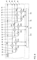
- Fig. 7 shows an advantageous arrangement of Receive antennas 36, 56 and 76 shows.
- the radar device 70 has a radar sensor 80 on, with respect to the radar sensor 40 further galvanic separations 72, 73, 74, more Mixer 78, 79 and a further phase shifter 77 has.
- Radar sensor 80 also has the receiving antenna 76 for receiving one of an object such as the obstacle 20th reflected reflection signal r3 (t) of the radiated transmission signal s (t).
- the radar device 70 has an evaluation device 81 for determining the angle ⁇ between the beam direction and the object 20 in the coordinate x and z spanned plane and the angle ⁇ between the beam direction and the object 20 in the by the coordinates y and z plane spanned and optionally the distance R and the Speed difference v as a function of in-phase signals I1 (t), I2 (t), I3 (t) and Quadrature signals Q1 (t), Q2 (t), Q3 (t) on.
- the evaluation device 81 with appropriate adjustments according to the evaluation device 41 configured.
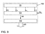
- FIG. 9 shows an exemplary embodiment of a driver assistance system 100.
- the driver assistance system 100 includes the radar device 70. But it can also be provided that the Driver assistance system 100, the radar device 30 has.
- the driving assistance system 100 has an evaluator 101 for generating a warning information WI as a function of the angle ⁇ between the beam direction of the radar device 70 and the object 20 and in Dependence of the distance R between the radar device 70 and the object 20 as well optionally as a function of the angle ⁇ between the beam direction of the radar device 70 and / or the object 20 and the speed difference v between the radar device 70 and the object 20.
- the warning information WI is also in Dependence of a state FA of a driving direction indicator can be generated.
- the driver assistance system 100 also has an output device 102 for optical, acoustic and / or haptic output of a warning signal WS as a function of Warning information WI on.
- the measuring or radar devices according to the invention can advantageously be in one Driver assistance system according to DE 42 28 794 A1 are used.
Landscapes
- Engineering & Computer Science (AREA)
- Radar, Positioning & Navigation (AREA)
- Remote Sensing (AREA)
- Physics & Mathematics (AREA)
- Computer Networks & Wireless Communication (AREA)
- General Physics & Mathematics (AREA)
- Electromagnetism (AREA)
- Radar Systems Or Details Thereof (AREA)
Applications Claiming Priority (4)
| Application Number | Priority Date | Filing Date | Title |
|---|---|---|---|
| DE10345588 | 2003-09-29 | ||
| DE10345588 | 2003-09-29 | ||
| DE10357704A DE10357704A1 (de) | 2003-09-29 | 2003-12-09 | Messgerät für ein Kraftfahrzeug |
| DE10357704 | 2003-12-09 |
Publications (2)
| Publication Number | Publication Date |
|---|---|
| EP1519204A1 true EP1519204A1 (fr) | 2005-03-30 |
| EP1519204B1 EP1519204B1 (fr) | 2010-03-24 |
Family
ID=34195778
Family Applications (1)
| Application Number | Title | Priority Date | Filing Date |
|---|---|---|---|
| EP04022028A Expired - Lifetime EP1519204B1 (fr) | 2003-09-29 | 2004-09-16 | Radar multistatique pour véhicule |
Country Status (1)
| Country | Link |
|---|---|
| EP (1) | EP1519204B1 (fr) |
Cited By (3)
| Publication number | Priority date | Publication date | Assignee | Title |
|---|---|---|---|---|
| WO2010000216A1 (fr) * | 2008-07-02 | 2010-01-07 | Adc Automotive Distance Control Systems Gmbh | Système de radar pour véhicule et procédé de détermination de la position d'au moins un objet par rapport à un véhicule |
| EP1680688B1 (fr) * | 2003-10-25 | 2016-09-14 | Volkswagen Aktiengesellschaft | Dispositif de mesure pour vehicule automobile |
| CN113189576A (zh) * | 2021-04-09 | 2021-07-30 | 电子科技大学 | 一种基于压缩感知的快速斜坡模式lfmcw车载雷达信号处理方法 |
Citations (11)
| Publication number | Priority date | Publication date | Assignee | Title |
|---|---|---|---|---|
| DE4228794A1 (de) * | 1992-08-29 | 1994-03-03 | Bosch Gmbh Robert | Einrichtung zur Überwachung des toten Winkels bei Fahrzeugen |
| DE4244608A1 (de) * | 1992-12-31 | 1994-07-07 | Volkswagen Ag | Computerisiertes Radarverfahren zur Messung von Abständen und Relativgeschwindigkeiten zwischen einem Fahrzeug und vor ihm befindlichen Hindernissen |
| DE4331440A1 (de) * | 1993-09-16 | 1995-03-23 | Deutsche Aerospace | Radargerät |
| DE19543813A1 (de) * | 1995-11-24 | 1997-05-28 | Bosch Gmbh Robert | Radarsystem, insbesondere Kraftfahrzeug-Radarsystem |
| EP0936473A1 (fr) * | 1998-02-16 | 1999-08-18 | Honda Giken Kogyo Kabushiki Kaisha | Dispositif radar installé sur un véhicule pour la gestion d'informations de réflecteurs |
| DE19922411A1 (de) * | 1999-04-07 | 2000-10-12 | Volkswagen Ag | Radarverfahren zur Messung von Abständen und Relativgeschwindigkeiten zwischen einem Fahrzeug und einem oder mehreren Hindernissen |
| US6215438B1 (en) * | 1996-06-28 | 2001-04-10 | Cambridge Consultants Limited | Vehicle radar system |
| WO2001026183A1 (fr) * | 1999-10-06 | 2001-04-12 | Robert Bosch Gmbh | Detecteur radar asymetrique a plusieurs faisceaux |
| WO2001059473A2 (fr) * | 2000-02-08 | 2001-08-16 | Cambridge Consultants Limited | Procedes et appareil pour la production d'informations de position |
| DE10025844A1 (de) * | 2000-05-25 | 2001-12-06 | Adc Automotive Dist Control | Verfahren zur Bestimmung der Entfernung zwischen einem Bezugsobjekt und mindestens einem Zielobjekt |
| WO2002031529A2 (fr) * | 2000-10-10 | 2002-04-18 | S.M.S Smart Microwave Sensors Gmbh | Procede et dispositif pour determiner l"eloignement d"un objet eloigne et la vitesse relative de celui-ci |
-
2004
- 2004-09-16 EP EP04022028A patent/EP1519204B1/fr not_active Expired - Lifetime
Patent Citations (11)
| Publication number | Priority date | Publication date | Assignee | Title |
|---|---|---|---|---|
| DE4228794A1 (de) * | 1992-08-29 | 1994-03-03 | Bosch Gmbh Robert | Einrichtung zur Überwachung des toten Winkels bei Fahrzeugen |
| DE4244608A1 (de) * | 1992-12-31 | 1994-07-07 | Volkswagen Ag | Computerisiertes Radarverfahren zur Messung von Abständen und Relativgeschwindigkeiten zwischen einem Fahrzeug und vor ihm befindlichen Hindernissen |
| DE4331440A1 (de) * | 1993-09-16 | 1995-03-23 | Deutsche Aerospace | Radargerät |
| DE19543813A1 (de) * | 1995-11-24 | 1997-05-28 | Bosch Gmbh Robert | Radarsystem, insbesondere Kraftfahrzeug-Radarsystem |
| US6215438B1 (en) * | 1996-06-28 | 2001-04-10 | Cambridge Consultants Limited | Vehicle radar system |
| EP0936473A1 (fr) * | 1998-02-16 | 1999-08-18 | Honda Giken Kogyo Kabushiki Kaisha | Dispositif radar installé sur un véhicule pour la gestion d'informations de réflecteurs |
| DE19922411A1 (de) * | 1999-04-07 | 2000-10-12 | Volkswagen Ag | Radarverfahren zur Messung von Abständen und Relativgeschwindigkeiten zwischen einem Fahrzeug und einem oder mehreren Hindernissen |
| WO2001026183A1 (fr) * | 1999-10-06 | 2001-04-12 | Robert Bosch Gmbh | Detecteur radar asymetrique a plusieurs faisceaux |
| WO2001059473A2 (fr) * | 2000-02-08 | 2001-08-16 | Cambridge Consultants Limited | Procedes et appareil pour la production d'informations de position |
| DE10025844A1 (de) * | 2000-05-25 | 2001-12-06 | Adc Automotive Dist Control | Verfahren zur Bestimmung der Entfernung zwischen einem Bezugsobjekt und mindestens einem Zielobjekt |
| WO2002031529A2 (fr) * | 2000-10-10 | 2002-04-18 | S.M.S Smart Microwave Sensors Gmbh | Procede et dispositif pour determiner l"eloignement d"un objet eloigne et la vitesse relative de celui-ci |
Non-Patent Citations (3)
| Title |
|---|
| BENLARBI-DELAI A ET AL: "MICROWAVE SHORT-RANGE INTERFEROMETRIC RADAR", INTERNATIONAL CONFERENCE ON MODELING AND SIMULATION OF MICROSYSTEMS, SEMICONDUCTORS, SENSORS AND ACTUATORS, PROCEEDINGS OF MODELLING AND SIMULATION OF MICROSYSTEMS, SEMICONDUCTORS, SENSORS AND ACTUATORS, XX, XX, 6 April 1998 (1998-04-06), pages 637 - 642, XP001006127 * |
| STEENSTRA H T ET AL: "3D VELOCITY MEASUREMENTS BY MEANS OF HIGH RESOLUTION SPARSE ARRAY RADAR", 30TH EUROPEAN MICROWAVE CONFERENCE PROCEEDINGS. PARIS, OCT. 3 - 5, 2000, PROCEEDINGS OF THE EUROPEAN MICROWAVE CONFERENCE, LONDON : CMP, GB, vol. VOL. 3 OF 3 CONF. 30, 5 October 2000 (2000-10-05), pages 100 - 103, XP001060986, ISBN: 0-86213-212-6 * |
| SWART P J F ET AL: "COLLISION AVOIDANCE RADAR ABLE TO DIFFERENTIATE OBJECTS", 27TH EUROPEAN MICROWAVE CONFERENCE PROCEEDINGS. JERUSALEM, SEPT. 8 - 12, 1997, PROCEEDINGS OF THE EUROPEAN MICROWAVE CONFERENCE, JERUSALEM : ORTRA LTD, IL, vol. VOL. 1 OF 2, 8 September 1997 (1997-09-08), pages 45 - 50, XP001072423 * |
Cited By (4)
| Publication number | Priority date | Publication date | Assignee | Title |
|---|---|---|---|---|
| EP1680688B1 (fr) * | 2003-10-25 | 2016-09-14 | Volkswagen Aktiengesellschaft | Dispositif de mesure pour vehicule automobile |
| WO2010000216A1 (fr) * | 2008-07-02 | 2010-01-07 | Adc Automotive Distance Control Systems Gmbh | Système de radar pour véhicule et procédé de détermination de la position d'au moins un objet par rapport à un véhicule |
| CN113189576A (zh) * | 2021-04-09 | 2021-07-30 | 电子科技大学 | 一种基于压缩感知的快速斜坡模式lfmcw车载雷达信号处理方法 |
| CN113189576B (zh) * | 2021-04-09 | 2021-12-03 | 电子科技大学 | 一种基于压缩感知的快速斜坡模式lfmcw车载雷达信号处理方法 |
Also Published As
| Publication number | Publication date |
|---|---|
| EP1519204B1 (fr) | 2010-03-24 |
Similar Documents
| Publication | Publication Date | Title |
|---|---|---|
| DE102018132745B4 (de) | Fmcw radar mit störsignalunterdrückung im zeitbereich | |
| EP2629113B1 (fr) | Système radar doté d'agencements et procédé pour découpler des signaux d'émission et de réception ainsi que pour annuler des rayonnements parasites | |
| DE102008014786B4 (de) | Verfahren zur Bestimmung des Pegels eines Grundrauschens und Radar zur Anwendung des Verfahrens sowie eine Interferenzerfassungsvorrichtung | |
| DE112010005193B4 (de) | Hindernis-Erfassungsvorrichtung | |
| EP1864155B1 (fr) | Procede et dispositif de mesure de distance et de vitesse relative de plusieurs objets | |
| EP1680688B1 (fr) | Dispositif de mesure pour vehicule automobile | |
| DE102012021973A1 (de) | Verfahren zum Betreiben eines Radarsensors eines Kraftfahrzeugs, Fahrerassistenzeinrichtung und Kraftfahrzeug | |
| DE102012024999A1 (de) | Verfahren zum Einstellen einer Detektionsschwelle für ein Empfangssignal eines Frequenzmodulations-Dauerstrich-Radarsensors eines Kraftfahrzeugs abhängig vom Rauschpegel, Radarsensor und Kraftfahrzeug | |
| DE102006028465A1 (de) | Kraftfahrzeug-Radarsystem und Verfahren zur Bestimmung von Geschwindigkeiten und Entfernungen von Objekten relativ zu dem einen Radarsystem | |
| DE102009016480A1 (de) | Radarsystem zur Unterdrückung von Mehrdeutigkeiten bei der Bestimmung von Objektmaßen | |
| DE102012024998A1 (de) | Verfahren zum Bestimmen einer lateralen Geschwindigkeit eines Zielobjekts relativ zu einem Kraftfahrzeug mit Hilfe eines Radarsensors, Fahrerassistenzsystem und Kraftfahrzeug | |
| DE10350553A1 (de) | Vorrichtung sowie Verfahren zum Erfassen, zum Detektieren und/oder zum Auswerten von mindestens einem Objekt | |
| EP3752852A1 (fr) | Estimation de vitesses cartésiennes d'objets radar étendus au moyen d'un capteur radar | |
| EP2062068A1 (fr) | Procédé de fonctionnement d'un système radar pour véhicule automobile et système radar pour véhicule automobile | |
| DE102017129149A1 (de) | Verfahren zur Ermittlung von wenigstens einer Objektinformation wenigstens eines Zielobjekts, das mit einem Radarsystem insbesondere eines Fahrzeugs erfasst wird, Radarsystem und Fahrerassistenzsystem | |
| DE102012004320A1 (de) | Verfahren und Vorrichtung zur Umfelderfassung unter Ausnutzung des Dopplereffekts | |
| DE102018100567B4 (de) | Verfahren zum Bestimmen einer Position eines Objekts mit Richtungsschätzung mittels eines Ultraschallsensors, Steuergerät, Ultraschallsensorvorrichtung sowie Fahrerassistenzsystem | |
| DE10348216A1 (de) | Objekterfassungssystem für ein Fahrzeug | |
| DE10357704A1 (de) | Messgerät für ein Kraftfahrzeug | |
| EP1519204B1 (fr) | Radar multistatique pour véhicule | |
| EP1431776B1 (fr) | Procédé pour déterminer la longueur d'un objet avec un système radar | |
| DE102004051690A1 (de) | Kraftfahrzeug mit einem Parklückendetektor | |
| DE10355249B4 (de) | Fahrassistenzsystem für ein Kraftfahrzeug | |
| DE102008034997A1 (de) | Verfahren zum Bestimmen der Azimutwinkel von Objekten in Bezug auf ein Messgerät | |
| EP1600793A2 (fr) | Capteur radar pour véhicules motorisés |
Legal Events
| Date | Code | Title | Description |
|---|---|---|---|
| PUAI | Public reference made under article 153(3) epc to a published international application that has entered the european phase |
Free format text: ORIGINAL CODE: 0009012 |
|
| AK | Designated contracting states |
Kind code of ref document: A1 Designated state(s): AT BE BG CH CY CZ DE DK EE ES FI FR GB GR HU IE IT LI LU MC NL PL PT RO SE SI SK TR |
|
| AX | Request for extension of the european patent |
Extension state: AL HR LT LV MK |
|
| 17P | Request for examination filed |
Effective date: 20050930 |
|
| AKX | Designation fees paid |
Designated state(s): AT BE BG CH CY CZ DE DK EE ES FI FR GB GR HU IE IT LI LU MC NL PL PT RO SE SI SK TR |
|
| GRAP | Despatch of communication of intention to grant a patent |
Free format text: ORIGINAL CODE: EPIDOSNIGR1 |
|
| GRAS | Grant fee paid |
Free format text: ORIGINAL CODE: EPIDOSNIGR3 |
|
| GRAA | (expected) grant |
Free format text: ORIGINAL CODE: 0009210 |
|
| AK | Designated contracting states |
Kind code of ref document: B1 Designated state(s): AT BE BG CH CY CZ DE DK EE ES FI FR GB GR HU IE IT LI LU MC NL PL PT RO SE SI SK TR |
|
| REG | Reference to a national code |
Ref country code: GB Ref legal event code: FG4D Free format text: NOT ENGLISH |
|
| REG | Reference to a national code |
Ref country code: CH Ref legal event code: EP |
|
| REG | Reference to a national code |
Ref country code: IE Ref legal event code: FG4D |
|
| REF | Corresponds to: |
Ref document number: 502004010932 Country of ref document: DE Date of ref document: 20100506 Kind code of ref document: P |
|
| REG | Reference to a national code |
Ref country code: NL Ref legal event code: VDEP Effective date: 20100324 |
|
| PG25 | Lapsed in a contracting state [announced via postgrant information from national office to epo] |
Ref country code: PL Free format text: LAPSE BECAUSE OF FAILURE TO SUBMIT A TRANSLATION OF THE DESCRIPTION OR TO PAY THE FEE WITHIN THE PRESCRIBED TIME-LIMIT Effective date: 20100324 Ref country code: FI Free format text: LAPSE BECAUSE OF FAILURE TO SUBMIT A TRANSLATION OF THE DESCRIPTION OR TO PAY THE FEE WITHIN THE PRESCRIBED TIME-LIMIT Effective date: 20100324 Ref country code: SI Free format text: LAPSE BECAUSE OF FAILURE TO SUBMIT A TRANSLATION OF THE DESCRIPTION OR TO PAY THE FEE WITHIN THE PRESCRIBED TIME-LIMIT Effective date: 20100324 |
|
| REG | Reference to a national code |
Ref country code: IE Ref legal event code: FD4D |
|
| PG25 | Lapsed in a contracting state [announced via postgrant information from national office to epo] |
Ref country code: EE Free format text: LAPSE BECAUSE OF FAILURE TO SUBMIT A TRANSLATION OF THE DESCRIPTION OR TO PAY THE FEE WITHIN THE PRESCRIBED TIME-LIMIT Effective date: 20100324 Ref country code: SE Free format text: LAPSE BECAUSE OF FAILURE TO SUBMIT A TRANSLATION OF THE DESCRIPTION OR TO PAY THE FEE WITHIN THE PRESCRIBED TIME-LIMIT Effective date: 20100324 Ref country code: RO Free format text: LAPSE BECAUSE OF FAILURE TO SUBMIT A TRANSLATION OF THE DESCRIPTION OR TO PAY THE FEE WITHIN THE PRESCRIBED TIME-LIMIT Effective date: 20100324 Ref country code: NL Free format text: LAPSE BECAUSE OF FAILURE TO SUBMIT A TRANSLATION OF THE DESCRIPTION OR TO PAY THE FEE WITHIN THE PRESCRIBED TIME-LIMIT Effective date: 20100324 Ref country code: ES Free format text: LAPSE BECAUSE OF FAILURE TO SUBMIT A TRANSLATION OF THE DESCRIPTION OR TO PAY THE FEE WITHIN THE PRESCRIBED TIME-LIMIT Effective date: 20100705 Ref country code: GR Free format text: LAPSE BECAUSE OF FAILURE TO SUBMIT A TRANSLATION OF THE DESCRIPTION OR TO PAY THE FEE WITHIN THE PRESCRIBED TIME-LIMIT Effective date: 20100625 |
|
| PG25 | Lapsed in a contracting state [announced via postgrant information from national office to epo] |
Ref country code: SK Free format text: LAPSE BECAUSE OF FAILURE TO SUBMIT A TRANSLATION OF THE DESCRIPTION OR TO PAY THE FEE WITHIN THE PRESCRIBED TIME-LIMIT Effective date: 20100324 Ref country code: BG Free format text: LAPSE BECAUSE OF FAILURE TO SUBMIT A TRANSLATION OF THE DESCRIPTION OR TO PAY THE FEE WITHIN THE PRESCRIBED TIME-LIMIT Effective date: 20100624 Ref country code: CZ Free format text: LAPSE BECAUSE OF FAILURE TO SUBMIT A TRANSLATION OF THE DESCRIPTION OR TO PAY THE FEE WITHIN THE PRESCRIBED TIME-LIMIT Effective date: 20100324 |
|
| PLBE | No opposition filed within time limit |
Free format text: ORIGINAL CODE: 0009261 |
|
| STAA | Information on the status of an ep patent application or granted ep patent |
Free format text: STATUS: NO OPPOSITION FILED WITHIN TIME LIMIT |
|
| PG25 | Lapsed in a contracting state [announced via postgrant information from national office to epo] |
Ref country code: DK Free format text: LAPSE BECAUSE OF FAILURE TO SUBMIT A TRANSLATION OF THE DESCRIPTION OR TO PAY THE FEE WITHIN THE PRESCRIBED TIME-LIMIT Effective date: 20100324 Ref country code: PT Free format text: LAPSE BECAUSE OF FAILURE TO SUBMIT A TRANSLATION OF THE DESCRIPTION OR TO PAY THE FEE WITHIN THE PRESCRIBED TIME-LIMIT Effective date: 20100726 Ref country code: IE Free format text: LAPSE BECAUSE OF FAILURE TO SUBMIT A TRANSLATION OF THE DESCRIPTION OR TO PAY THE FEE WITHIN THE PRESCRIBED TIME-LIMIT Effective date: 20100324 |
|
| 26N | No opposition filed |
Effective date: 20101228 |
|
| BERE | Be: lapsed |
Owner name: VOLKSWAGEN A.G. Effective date: 20100930 |
|
| PG25 | Lapsed in a contracting state [announced via postgrant information from national office to epo] |
Ref country code: IT Free format text: LAPSE BECAUSE OF FAILURE TO SUBMIT A TRANSLATION OF THE DESCRIPTION OR TO PAY THE FEE WITHIN THE PRESCRIBED TIME-LIMIT Effective date: 20100324 |
|
| PG25 | Lapsed in a contracting state [announced via postgrant information from national office to epo] |
Ref country code: MC Free format text: LAPSE BECAUSE OF NON-PAYMENT OF DUE FEES Effective date: 20100930 |
|
| REG | Reference to a national code |
Ref country code: CH Ref legal event code: PL |
|
| GBPC | Gb: european patent ceased through non-payment of renewal fee |
Effective date: 20100916 |
|
| REG | Reference to a national code |
Ref country code: FR Ref legal event code: ST Effective date: 20110531 |
|
| REG | Reference to a national code |
Ref country code: DE Ref legal event code: R084 Ref document number: 502004010932 Country of ref document: DE |
|
| PG25 | Lapsed in a contracting state [announced via postgrant information from national office to epo] |
Ref country code: FR Free format text: LAPSE BECAUSE OF NON-PAYMENT OF DUE FEES Effective date: 20100930 Ref country code: BE Free format text: LAPSE BECAUSE OF NON-PAYMENT OF DUE FEES Effective date: 20100930 Ref country code: CH Free format text: LAPSE BECAUSE OF NON-PAYMENT OF DUE FEES Effective date: 20100930 Ref country code: LI Free format text: LAPSE BECAUSE OF NON-PAYMENT OF DUE FEES Effective date: 20100930 |
|
| PG25 | Lapsed in a contracting state [announced via postgrant information from national office to epo] |
Ref country code: GB Free format text: LAPSE BECAUSE OF NON-PAYMENT OF DUE FEES Effective date: 20100916 |
|
| REG | Reference to a national code |
Ref country code: DE Ref legal event code: R084 Ref document number: 502004010932 Country of ref document: DE Effective date: 20110514 |
|
| PG25 | Lapsed in a contracting state [announced via postgrant information from national office to epo] |
Ref country code: AT Free format text: LAPSE BECAUSE OF NON-PAYMENT OF DUE FEES Effective date: 20100916 |
|
| PG25 | Lapsed in a contracting state [announced via postgrant information from national office to epo] |
Ref country code: CY Free format text: LAPSE BECAUSE OF FAILURE TO SUBMIT A TRANSLATION OF THE DESCRIPTION OR TO PAY THE FEE WITHIN THE PRESCRIBED TIME-LIMIT Effective date: 20100324 |
|
| PG25 | Lapsed in a contracting state [announced via postgrant information from national office to epo] |
Ref country code: HU Free format text: LAPSE BECAUSE OF FAILURE TO SUBMIT A TRANSLATION OF THE DESCRIPTION OR TO PAY THE FEE WITHIN THE PRESCRIBED TIME-LIMIT Effective date: 20100925 Ref country code: LU Free format text: LAPSE BECAUSE OF NON-PAYMENT OF DUE FEES Effective date: 20100916 |
|
| PG25 | Lapsed in a contracting state [announced via postgrant information from national office to epo] |
Ref country code: TR Free format text: LAPSE BECAUSE OF FAILURE TO SUBMIT A TRANSLATION OF THE DESCRIPTION OR TO PAY THE FEE WITHIN THE PRESCRIBED TIME-LIMIT Effective date: 20100324 |
|
| PGFP | Annual fee paid to national office [announced via postgrant information from national office to epo] |
Ref country code: DE Payment date: 20200930 Year of fee payment: 17 |
|
| REG | Reference to a national code |
Ref country code: DE Ref legal event code: R119 Ref document number: 502004010932 Country of ref document: DE |
|
| PG25 | Lapsed in a contracting state [announced via postgrant information from national office to epo] |
Ref country code: DE Free format text: LAPSE BECAUSE OF NON-PAYMENT OF DUE FEES Effective date: 20220401 |