EP0936501B1 - Appareil de développement automatique - Google Patents
Appareil de développement automatique Download PDFInfo
- Publication number
- EP0936501B1 EP0936501B1 EP99102475A EP99102475A EP0936501B1 EP 0936501 B1 EP0936501 B1 EP 0936501B1 EP 99102475 A EP99102475 A EP 99102475A EP 99102475 A EP99102475 A EP 99102475A EP 0936501 B1 EP0936501 B1 EP 0936501B1
- Authority
- EP
- European Patent Office
- Prior art keywords
- rollers
- shaft
- liquid surface
- diameter
- torque
- Prior art date
- Legal status (The legal status is an assumption and is not a legal conclusion. Google has not performed a legal analysis and makes no representation as to the accuracy of the status listed.)
- Expired - Lifetime
Links
Images


Classifications
-
- G—PHYSICS
- G03—PHOTOGRAPHY; CINEMATOGRAPHY; ANALOGOUS TECHNIQUES USING WAVES OTHER THAN OPTICAL WAVES; ELECTROGRAPHY; HOLOGRAPHY
- G03D—APPARATUS FOR PROCESSING EXPOSED PHOTOGRAPHIC MATERIALS; ACCESSORIES THEREFOR
- G03D3/00—Liquid processing apparatus involving immersion; Washing apparatus involving immersion
- G03D3/08—Liquid processing apparatus involving immersion; Washing apparatus involving immersion having progressive mechanical movement of exposed material
- G03D3/13—Liquid processing apparatus involving immersion; Washing apparatus involving immersion having progressive mechanical movement of exposed material for long films or prints in the shape of strips, e.g. fed by roller assembly
- G03D3/132—Liquid processing apparatus involving immersion; Washing apparatus involving immersion having progressive mechanical movement of exposed material for long films or prints in the shape of strips, e.g. fed by roller assembly fed by roller assembly
Definitions
- the present invention relates to an automatic developing apparatus in which a film transport unit provided with film transport rollers is sunk in a treatment tank containing treatment liquid used for the development of a film or like photosensitive material to immerse the film in the treatment liquid to develop it and particularly to an automatic developing apparatus in which a torque is transmitted from the outside of the treatment tank to the film transport rollers via the liquid surface in the treatment tank.
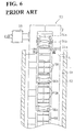
- Known automatic developing apparatuses include a plurality of treatment tanks 52 for containing treatment liquids 51 which are liquid agents such as developer, bleaching liquid and fixer, for example, as shown in FIG. 4.
- Transport units (hereinafter, "rack") 53 provided with a plurality of transport rollers for transporting a photosensitive material such as a film are sunk in the respective treatment tanks 52, so that the film can be developed by being immersed in the respective treatment liquids 51 while being transported in the respective treatment tanks 52.
- the film developed by being passed through the respective treatment tanks 52 is then transported to an unillustrated drying assembly to be dried and discharged from the apparatus.
- the aforementioned plurality of transport rollers of the rack 53 include a pair of feed rollers 54a, 54b, large-diameter rollers 55a, 55b, 55c, ..., first small-diameter rollers 56a, 56b, 56c, ..., second small-diameter rollers 57a, 57b, 57c, ... and reverse rollers (not shown). These rollers are so provided that the axis of rotations thereof all extend along the widthwise direction of the film.
- the reverse rollers are provided at the bottom end of the rack 53 without being held in contact with any other roller, and a transport direction of the film being transported is reversed by being guided by the circumferential surfaces of the
- the feed rollers 54a, 54b are adapted to introduce the film into the treatment tank 52 and are so arranged near a film inlet as to face each other.
- the large-diameter roller 55a is provided in an inner upper portion of the rack 53 such that a portion of its circumferential surface crosses liquid surface L of the treatment liquid 51 in the treatment tank 52.
- the large-diameter rollers 55b, 55c, ... are provided in this order in downward direction from the large-diameter roller 55a so that intervals between the successive rollers (including an interval between the large-diameter rollers 55a and 55b) are substantially equal, and are completely immersed in the treatment liquid 51.
- the first small-diameter rollers 56a, 56b, 56c, ... are provided to face the large-diameter rollers 55a, 55b, 55c, ... so that the film introduced by the pair of feed rollers 54a, 54b can be transported by the rotation of the respective pairs of the large-diameter and small-diameter rollers while being tightly held.
- the second small-diameter rollers 57a, 57b, 57c ... are provided to face the large-diameter rollers 55a, 55b, 55c, ... at the side opposite from the first small-diameter rollers 56a, 56b, 56c, ... so that the film having its transport direction reversed by the reverse rollers can be transported by the rotation of the respective pairs of the large-diameter and small-diameter rollers while being tightly held.
- a torque to be given to these transport rollers is transmitted from a drive source (not shown) outside the treatment tank 52 via gears and spur gears provided in the treatment tank 52.
- a drive source not shown
- spur gears provided in the treatment tank 52.
- the large-diameter rollers 55a, 55b, 55c, ..., the first small-diameter rollers 56a, 56b, 56c, ... and the second small-diameter rollers 57a, 57b, 57c, ... shown in FIG. 4 are connected with first spur gears 65a, 65b, 65c, ..., second spur gears 66a, 66b, 66c, ... and third spur gears 67a, 67b, 67c, ... while sharing the same rotatable shafts.
- the first spur gears 65a, 65b, 65c ... are in mesh with the second spur gears 66a, 66b, 66c ... and also with the third spur gears 67a, 67b, 67c ..., respectively.
- the first spur gear 65a integrally provided with the large-diameter roller 55a is, similar to the large-diameter roller 55a, provided such that a portion of the teeth portion on its circumferential surface crosses the liquid surface L of the treatment liquid 51 in the treatment tank 52 when the rack 53 is set in the treatment tank 52. Further, the reverse rollers are connected with the first spur gear located in a bottommost position in the rack 53 while sharing the same rotatable shaft.
- Fourth spur gears 68a, 68b, 68c ... are provided between the first spur gears 65a and 65b, between the first spur gears 65b and 65c, ... such that each is in mesh with the corresponding pair of the first spur gears.
- the first spur gear 65a located in an uppermost position in the rack 53 is in mesh with a fifth spur gear 70 provided coaxially with a gear 69, to which a torque is transmitted from the drive source, at a side opposite from an engaging portion with the fourth spur gear 68a.
- spur gears provided coaxially with the feed rollers 54a, 54b are not illustrated.
- the torque from the drive source is transmitted to the feed rollers 54a, 54b at least via, e.g. the fifth spur gear 70 so that the feed rollers 54a, 54b are rotated to introduce the film between the large-diameter roller 55a and the first small-diameter roller 56a.
- the first spur gear 65b in mesh with the fourth spur gear 68a is rotated in the direction F by the rotation of the fourth spur gear 68a in the direction E, with the result that the second spur gear 66b, the third spur gear 67b and the fourth spur gear 68b which are in mesh with the first spur gear 65b are rotated in the direction E.
- the large-diameter rollers 55a, 55b, 55c, ... provided coaxially with the first spur gears 65a, 65b, 65c, ... are all rotated in the direction F by the rotation of all the first spur gears 65a, 65b, 65c, ... in the direction F.
- the first small-diameter rollers 56a, 56b, 56c, ... and the second small diameter rollers 57a, 57b, 57c, ... are all rotated in the direction E by the rotation of all the second spur gears 66a, 66b, 66c, ... and all the third spur gears 67a, 67b, 67c, ... in the direction E.
- the film having passed through the film inlet (not shown) and passed between the feed rollers 54a, 54b is transported to a lower side while being successively passing between the large-diameter roller 55a and the first small diameter roller 56a, between the large-diameter roller 55b and the first small-diameter roller 56b, ... by the rotation of the large-diameter rollers 55 and the first small-diameter rollers 56.
- the film After having the transport direction thereof reversed by the reverse rollers, the film is transported upward from the lower side while passing between the corresponding pairs of the large-diameter roller 55 and the second small-diameter rollers 57 by the rotation of the large-diameter rollers 55 and the second small-diameter rollers 57. Thereafter, the film is transported to the next treatment tank 52 while passing between the large-diameter roller 55a and the second small-diameter roller 57a. In other words, the film passes along a film transport path indicated by P in FIG. 4.
- FIG. 6 is a section along A-A of FIG. 4. As shown in FIG. 6, slit-shaped outlets 58 are formed in positions corresponding to the film transport path inside the rack 53 and the treatment liquid 51 is admitted into the treatment tank 52 through the outlets 58.
- the scooped treatment liquid 51 is also passed onto the second spur gear 66a, the third spur gear 67a and the fifth spur gear 70 in mesh with the third spur gear 65a and is solidified on the circumferential surfaces of these spur gears. This results in loads acting on the torque transmission from the drive source and an unsatisfactory torque transmission, thereby hindering the film transport.
- US-A-5 134 430 relates to a conveyor rack for conveying photosensitive material within a submerged treatment area such as a developing tank, wherein the conveying rollers below the liquid surface are driven by a worm gear mechanism, comprising a single main driving shaft mounted with a number of bevel gears with which a worm gear attached on the driven shaft of each roller is meshed.
- EP-A- 0 622 676, GB 962 798 A, EP-A-0 608 859 and GB-953 584 A relate to roller conveyor units comprising a plurality of vertically spaced sets of rollers for feeding film or the like along a prescribed path through a processing tank, the rollers are rotatably arranged in a mounting receivable in said tanks, a vertically disposed common drive spinner for driving the rollers of all the sets, and individual take-off gearing for each set for driving the rollers of that set from the spindle.
- the invention is directed to an automatic developing apparatus comprising a treatment tank for containing a treatment liquid used to develop a photosensitive material, and a transport unit comprising a plurality of sets of transport rollers for transporting the photosensitive material, wherein the photosensitive material is developed by sinking the transport unit in the treatment tank to thereby immerse the photosensitive material in the treatment liquid, comprising:
- the torque transmitting means is comprised of the shaft-shaped transmitting portion which has the axis of rotation extending normal to the liquid surface and is so arranged as to cross the liquid surface, and the remaining portion which is so arranged as not to cross the liquid surface.
- the torque is transmitted from the above of the liquid surface to the below of the liquid surface via the shaft-shaped transmitting portion.
- only the shaft-shaped transmitting portion is in contact with the liquid surface of the treatment liquid, but the portion other than the shaft-shaped transmitting portion is out of contact with the liquid surface.
- the shaft-shaped transmitting portion is rotated about the axis of rotation extending normal to the liquid surface, the treatment liquid in contact therewith is left in contact with this transmitting portion at a specified height position. Accordingly, the rotation of the shaft-shaped transmitting portion does not cause the treatment liquid to be passed onto the torque transmitting means located above the liquid surface via the shaft-shaped transmitting portion. Therefore, unlike the prior art, there is no likelihood that the drive of the torque transmitting means is hindered by the solidification of the treatment liquid thereon.
- the torque can be smoothly transmitted from the outside of the treatment tank to the respective transport rollers via the liquid surface of the treatment liquid without creating superfluous loads, with the result that the photosensitive material can be satisfactorily transported.
- the shaft-shaped transmitting portion is rotated about the axis of rotation extending normal to the liquid surface, the treatment liquid near the liquid surface will not be scooped up during the rotation of the shaft-shaped transmitting portion unlike the prior art.
- the shaft-shaped transmitting portion has a cylindrical shape.
- the shaft-shaped transmitting portion By making the shaft-shaped transmitting portion cylindrical, the cross section thereof in the liquid surface of the treatment liquid does not change regardless of whether it is stationary or in rotation. Accordingly, as compared to a case where the shaft-shaped transmitting portion is in the shape of, e.g. a rectangular prism, the liquid surface is unlikely to be rippled and, as a result, there is little likelihood that the treatment liquid is mixed with air by the rotation of the shaft-shaped transmitting portion. Therefore, in the case that the shaft-shaped transmitting portion has a cylindrical shape, the oxidation and evaporation of the treatment liquid can be considerably slowed down as compared to a case where it has any other shape. As a result, the treatment liquid can be used for a longer period of time while avoiding a reduction in its quality.
- the torque transmitting means further comprises a first rotatable shaft above the liquid surface and at least one second rotatable shaft below the liquid surface, the first and second shafts extending in parallel with the liquid surface and each being connected to the shaft-shaped transmitting portion by torque transmission gears.
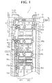
- An automatic developing apparatus is provided with a treatment tank 2 for containing treatment liquid 1 used for developing a film or like photosensitive material, and a rack 3 (transport unit) including a plurality of transport rollers for transporting the film.
- the rack 3 is sunk in the treatment tank 2 to immerse the film in the treatment liquid 1, thereby developing the film.
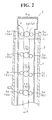
- the rack 3 includes a first transport path W1 for transmitting a film having a width of 24 mm in accordance with the APS (advanced photo system), a second transport path W2 for transporting a so-called 135 size film having a width of 35 mm and the aforementioned plurality of transport rollers for the respective treatment paths.
- the first and second transport paths W1, W2 run parallel to each other, so that two kinds of films having different widths can be simultaneously transported for development.
- the respective transport rollers provided in the respective transport paths are described.
- the rack 3 include large-diameter rollers 4a, 4b, 4c, 4d, ... and first small-diameter rollers 5a, 5b, 5c, 5d, ... and second small-diameter rollers 6a, 6b, 6c, 6d, ... as transport rollers corresponding to the first transport path W1 shown in FIG. 1, and an unillustrated pair of feed rollers and unillustrated reverse rollers.
- the respective rollers are all provided so that their axes of rotation extend along the widthwise direction of the film and in parallel with liquid surface L of the treatment liquid 1.
- the pair of feed rollers are adapted to introduce the film into the treatment tank 2, and are so arranged as to face each other near an unillustrated film inlet of the rack 3.
- the reverse rollers are provided at the bottom end of the rack 3 without being held in contact with any other roller, and a transport direction of the film being transported is reversed by being guided by the circumferential surfaces of the reverse rollers.
- the large-diameter roller 4a is provided in an upper position inside the rack 3 so that the circumferential surface thereof is not brought into contact with the liquid surface L of the treatment liquid 1 in the treatment tank 2 by its rotation even if the rack 3 is set in the treatment tank 2.
- the large-diameter rollers 4b, 4c, 4d ... are provided in this order in downward direction from the large-diameter roller 4a so that intervals between the successive rollers (excluding an interval between the large-diameter rollers 4a and 4b) are substantially equal, and are completely immersed in the treatment liquid 1.
- the first small-diameter rollers 5a, 5b, 5c, 5d, ... are so provided as to face the large-diameters 4a, 4b, 4c, 4d, ... so as to transport the film introduced by the pair of feed rollers by the rotation of the respective pairs of the large-diameter and small-diameter rollers while tightly holding the film.
- the second small-diameter rollers 6a, 6b, 6c, 6d ... are provided to face the large-diameter rollers 4a, 4b, 4c, 4d ... at the side opposite from the first small-diameter rollers 5a, 5b, 5c, 5d ... so that the film having its transport direction reversed by the reverse rollers can be transported by the rotation of the respective pairs of the large-diameter and small-diameter rollers while being tightly held.
- the rack 3 also includes large-diameter rollers 7a, 7b, 7c, 7d, ..., first small-diameter rollers 8a, 8b, 8c, 8d, ... and second small-diameter rollers 9a, 9b, 9c, 9d, ... as transport rollers corresponding to the second transport path W2 shown in FIG. 1, and an unillustrated pair of feed rollers and unillustrated reverse rollers.
- the large-diameter rollers 7a, 7b, 7c, 7d, ... and the large-diameter rollers 4a, 4b, 4c, 4d, ... share rotatable shafts 30a, 30b, 30c, 30d (see FIG. 1), respectively.
- first small-diameter rollers 8a, ... and the second small-diameter rollers 9a, ... are provided coaxially with the first small-diameter rollers 5a, ... and the second small-diameter rollers 9a, ..., respectively.
- the pair of feed rollers and the reverse rollers provided in the second transport path W2 are provided coaxially with the pair of feed rollers and the reverse roller provided in the first transport path W2, respectively.
- the large-diameter rollers 7a, ... and the first small-diameter rollers 8a, ... are arranged to face each other, respectively so as to transport the film introduced to the pair of feed rollers by the rotation of the respective pairs of the large-diameter rollers and the small-diameter rollers while tightly holding it.
- the large-diameter rollers 7a, ... and the second small-diameter rollers 9a, ... are provided to face each other, respectively at the opposite side from the first small-diameter rollers 8a, ...so as to transport the film having its transport direction reversed by the reverse roller by the rotation of the respective pairs of the large-diameter rollers 7a, ... and the second small-diameter rollers 9a, ... while tightly holding it.
- a shaft 11 having an axis of rotation extending in parallel with the rotatable shaft 30a of the large-diameter rollers 4a, 7a is provided above the large-diameter rollers 4a, 7a.
- a gear 12 coaxially rotatable with the shaft 11 by the torque from the drive source is secured to one end of the shaft 11.
- a first spur gear 13 is provided coaxially with the rollers 7a, 4a. This first spur gear 13 is in mesh with a second spur gear 14 which is coaxial with the shaft 11 and is secured in a position more inward than the gear 12 inside the rack 3.
- a bevel gear 15 is provided coaxially with the rollers 4a, 7a at a side of the rotatable shaft 30a opposite from the first spur gear 13.
- the first spur gear 13 and the bevel gear 15 are provided above the liquid surface L of the treatment liquid 1 so as not to scoop up the treatment liquid 1 by being brought into contact with the treatment liquid 1 in the treatment tank 1 while being rotated.
- a bevel gear 16 is provided coaxially with these rollers 4b, 7b opposite from the large-diameter roller 7b with respect to the large-diameter roller 4b.
- third spur gears 17c, 17d, ... are provided coaxially with these rollers.
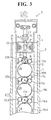
- fifth spur gears 19b, 19c, 19d, ... sharing the same rotatable shafts with these rollers are provided as shown in FIG. 3.
- the fifth spur gears 19b, 19c, 19d, ... are so provided as to be in mesh with the bevel gear 16, the third spur gears 17c, 17d, ... in this order, respectively.
- sixth spur gears 20b, 20c, 20d, ... sharing the same rotatable shafts with these rollers are provided, likewise, as shown in FIG. 3.
- the sixth spur gears 20b, 20c, 20d, ... are so provided as to be in mesh with the bevel gear 16, the third spur gears 17c, 17d, ... in this order at the opposite side from the fifth spur gears 19b, 19c, 19d, respectively.
- Spur gears provided coaxially with the pair of feed rollers are not illustrated.
- the torque from the drive source is transmitted to the feed rollers at least via, e.g. the second spur gear 14 so that the respective feed rollers can introduce the film between the large-diameter roller 4a (7a) and the first small-diameter roller 5a (8a) by their rotation.
- the respective reverse rollers are connected with the third spur gear located in a bottommost position in the rack 3 while sharing the same rotatable shaft therewith.
- a torque is transmitted from the bevel gear 15 to the bevel gear 16 via the liquid surface L by means of a shaft having an axis of rotation extending normal to the liquid surface L.
- the rack 3 is provided with a cylindrical shaft 21 (shaft-shaped transmitting portion) having an axis of rotation extending normal to the liquid surface L of the treatment liquid 1.
- This shaft 21 is made of metal such as SUS (stainless steel) 316 or resin which is unlikely to be oxidized by the treatment liquid 21, and is so arranged as to cross the liquid surface L of the treatment liquid 1 and supported by a shaft supporting member 22.
- a bevel gear 23 is secured coaxially with the shaft 21 in a position of the shaft 21 above the liquid surface L, whereas a bevel gear 24 is secured coaxially with the shaft 21 in a position of the shaft 21 below the liquid surface L.
- the bevel gear 23 is in mesh with an upper teeth portion 15a of the bevel gear 15 which is located above the rotatable shaft 30a, whereas the bevel gear 24 is in mesh with an upper teeth portion 16a of the bevel gear 16 which is located above the rotatable shaft 30b.
- the construction according to this embodiment for transmitting a torque from the outside of the treatment tank 2 to the bevel gears and spur gears arranged below the liquid surface L via the liquid surface L of the treatment liquid 1 is, unlike the prior art, not such that a torque transmitting member such as a gear located in vicinity of the liquid surface L and having an axis of rotation extending in parallel with the liquid surface L is brought into contact with the liquid surface L of the treatment liquid 1.
- the torque of the bevel gear 15 located above the liquid surface L and having the axis of rotation extending in parallel with the liquid surface L is translated into the torque of the shaft 21 having the axis of rotation extending normal to the liquid surface L, which is then transmitted to the bevel gear 16 located below the liquid surface L and having the axis of rotation extending in parallel with the liquid surface L.
- the treatment liquid 1 will not be scooped up as a matter of fact since the shaft 21 in contact with the liquid surface L of the treatment liquid 1 is rotated about the axis of rotation extending normal to the liquid surface L.
- the torque transmitting means of claim 1 for transmitting a torque from the drive source outside the treatment tank 2 to the respective transport rollers is constructed by the respective shafts, gears, spur gears, rotatable shafts and bevel gears.
- the rack 3 further includes slit-shaped discharge ports 10a for discharging the treatment liquid 1 toward the film being transported along the first transport path W1 and admitting it into the treatment tank 2, and slit-shaped discharge ports 10b for discharging the treatment liquid 1 toward the film being transported along the second transport path W2 and admitting it into the treatment tank 2. Opening areas of the respective discharge ports 10a, 10b correspond to the widths of the corresponding films.
- the automatic developing apparatus is provided with a heater (not shown) for heating the treatment liquid 1 to a suitable temperature and a pump (not shown) for circulating the treatment liquid 1 heated by the heater between the inside and outside of the treatment tank 2.
- a heater not shown
- a pump not shown
- the temperature of the treatment liquid 1 in the treatment tank 2 can be constantly maintained at a temperature suited for the development of the film.
- the fifth spur gear 19b, the sixth spur gear 20b and the fourth spur gear 18b which are in mesh with the bevel gear 16 as shown in FIG. 3 are rotated in the direction B.
- the rotation of the fourth spur gear 18b in the direction B causes the third spur gear 17c in mesh with the fourth spur gear 18b to rotate in the direction A.
- the fifth spur gears 19c, ..., the sixth spur gears 20c, ..., and the fourth spur gears 18c, ... are rotated in the direction B, whereas the third spur gears 17d, ... in mesh with the fourth spur gears 18c, ... are rotated in the direction A.
- the large-diameter rollers 4a, ... (large-diameter rollers 7a, ...) and the reverse rollers provided coaxially with the bevel gears 15, 16 and the third spur gears 1 7b, 1 7c, ... are all rotated in the direction A
- the second small-diameter rollers 6b, ... (second small-diameter rollers 9b, ...) provided coaxially with the sixth spur gears 20b, ... are all rotated in the direction B.
- a film having a width of 24 mm which has passed between the unillustrated film inlet and the feed rollers is transported downward while successively passing between the corresponding pairs of the large-diameter rollers 4 and the first small-diameter roller 5.
- the film After having its transport direction reversed from downward to upward by the reverse rollers, the film is transported upward from the bottom while passing successively between the corresponding pairs of the large-diameter rollers 4 and the second small-diameter rollers 6. Thereafter, the film is transported to the next treatment tank 2 after passing between the large-diameter roller 4a and the second small-diameter roller 6a.
- a film having a width of 35 mm is transported downward while successively passing between the corresponding pairs of the large-diameter rollers 7 and the first small-diameter rollers 8, has its transport direction reversed from downward to upward by the reverse rollers, and is then transported upward from the bottom while passing successively between the corresponding pairs of the large-diameter rollers 7 and the second small-diameter rollers 9.
- the film is transported to the next treatment tank 2 after passing between the large-diameter roller 7a and the second small-diameter roller 9a. In other words, this film passes along a film transport path indicated by an arrow P in FIG. 2.
- the shaft 21 is provided in a position where it can be in contact with the liquid surface L, and the torque is transmitted from the above of the liquid surface to the below of the liquid surface L by means of this shaft 21 according to the invention.
- the shaft 21 is rotated about the axis of rotation extending normal to the liquid surface L, the treatment liquid 1 in contact with the shaft 21 is left in contact with the shaft 21 at a specified height position even if the shaft 21 is rotated. Accordingly, the rotation of the shaft 21 does not cause the treatment liquid 1 to passed up onto, e.g.
- the bevel gears 23, 15 located above the liquid surface L via the shaft 21, with the result that the treatment liquid 1 is solidified on the bevel gears 23, 15 in no likelihood. Therefore, the torque can be smoothly transmitted to the respective transport rollers via the liquid surface L without causing any load on the rotation of the bevel gears 23, 15.
- the oxidization and evaporation of the treatment liquid 1 can be considerably restrained unlike the prior art. As a result of that, a reduction in the function of the treatment liquid 1 and a decrease in the quantity thereof can be securely suppressed. Therefore, even if the treatment liquid 1, which is specified to be used in small quantity and is, thus, likely to be influenced by the oxidation, is used, a satisfactory development in accordance with the specifications of each treatment liquid 1 can be ensured. Further, since the reduction in the function of the treatment liquid 1 is suppressed, it becomes easier to control the quality of the treatment liquid 1.
- the shaft 21 having the axis of rotation extending normal to the surface L has a cylindrical shape in this embodiment, the shape thereof is not particularly limited to it, provided that it has an axis of rotation extending normal to the liquid surface L.
- the shaft 21 may be in the shape of a polygonal prism, a cone, or an inverted cone. In such a case as well, the same effects as this embodiment can be obtained since the shaft 21 will not scoop up the treatment liquid 1 while being rotated.
- the shaft 21 has a cylindrical shape as in this embodiment, the cross section of the shaft 21 in the liquid surface L does not change regardless of whether the shaft 21 is stationary or in rotation.
- the liquid surface L is unlikely to be rippled and, accordingly, there is little likelihood that the treatment liquid 1 is mixed with air by the rotation of the shaft 21. Therefore, in the case that the shaft 21 has a cylindrical shape, the oxidation of the treatment liquid 1 can be considerably slowed down as compared to a case where it has any other shape. As a result, the treatment liquid 1 can be used for a longer period of time while avoiding a reduction in its quality.
- the treatment liquid 1 acts as loads on the respective side surfaces of the shaft 21 during the rotation of the shaft 21.
- the shaft 21 has a cylindrical shape, such loads can be considerably reduced. As a result, the torque can be more satisfactorily transmitted by more smoothly rotating the shaft 21.
- the surface of the shaft 21 is even in this embodiment, it may be made uneven, e.g. by forming grooves therein in order to further avoid the treatment liquid 1 being rippled during the rotation of the shaft 21.
- the invention is not limited to this torque transmitting construction.
- the invention may be applied to a construction in which the torque is transmitted to the respective transport rollers via a belt mechanism, a crank mechanism or a cam mechanism.
- the inventive automatic developing apparatus is provided with the torque transmitting means for transmitting the torque from the outside of the treatment tank to the respective transport rollers via the liquid surface of the treatment liquid.
- the torque transmitting means is comprised of the shaft-shaped transmitting portion having an axis of rotation extending normal to the liquid surface, wherein the shaft-shaped transmitting portion is so arranged as to cross the liquid surface, whereas a remaining portion of the torque transmitting means is so arranged as not to cross the liquid surface.
- the treatment liquid in contact with the shaft-shaped transmitting portion is left in contact therewith at a specified height position, and there is no likelihood that the treatment liquid is passed up onto the torque transmitting means located above the liquid surface via the shaft-shaped transmitting portion by the rotation of the shaft-shaped transmitting portion.
- the drive of the torque transmitting means will not be hindered by the solidification of the treatment liquid thereon. Therefore, according to the above construction, the torque can be smoothly transmitted from the outside of the treatment tank to the respective transport rollers via the liquid surface of the treatment liquid without creating superfluous loads, with the result that the film can be satisfactorily transported.
- the treatment liquid near the liquid surface will not be scooped up during the rotation of the shaft-shaped transmitting portion. This securely restrains the reaction of the treatment liquid with air to a larger degree than the prior art and, as a result, considerably restrains the oxidation and evaporation of the treatment liquid. Therefore, according to the above construction, a reduction in the function of the treatment liquid and a decrease in the quantity of the treatment liquid can be securely suppressed and, as a result, a satisfactory development in accordance with the specifications of the treatment liquid can be performed.
- the shaft-shaped transmitting portion is formed to have a cylindrical shape, the liquid surface is unlikely to be rippled and there is little likelihood that the treatment liquid is mixed with air by the rotation of the shaft-shaped transmitting portion as compared to a case where the shaft-shaped transmitting portion is in the shape of, e.g. a polygonal prism.
- the oxidation and evaporation of the treatment liquid can be considerably slowed down, and the treatment liquid can be used for a longer period of time while avoiding a reduction in its quality.
Landscapes
- Physics & Mathematics (AREA)
- General Physics & Mathematics (AREA)
- Photographic Processing Devices Using Wet Methods (AREA)
Claims (3)
- Appareil de développement automatique comprenant une cuve de traitement (2) pour contenir un liquide de traitement (1) utilisé pour développer un matériau photosensible, et une unité de transport (3) comportant une pluralité de groupes de rouleaux de transport (4-9) pour transporter le matériau photosensible, dans lequel le matériau photosensible est développé par plongée de l'unité de transport (3) dans la cuve de traitement (2) afin d'immerger le matériau photosensible dans le liquide de traitement (1), comprenant :dans lequel le dispositif de transmission de couple (11-21, 23, 24, 30) comprend en outre une partie de transmission en forme d'arbre (21) ayant un axe de rotation perpendiculaire à la surface du liquide (L), la partie de transmission en forme d'arbre (21) étant agencée de façon à croiser la surface du liquide (L) tandis que la partie restante du dispositif de transmission de couple (11-21, 23, 24, 30) est agencée de façon à ne pas traverser la surface du liquide (L),un dispositif de transmission de couple (11-21, 23, 24, 30) pour transmettre un couple de l'extérieur de la cuve de traitement (2) aux groupes respectifs de rouleaux de transport (4-9) situés au-dessous d'une surface du liquide (L) dans la cuve de traitement (2), et un mécanisme à engrenages (16-20) pour entraíner les groupes de rouleaux de transport (4b-9d) au-dessous de la surface du liquide (L),
caractérisé en ce que
la dite partie de transmission (21) est en prise avec un deuxième arbre (30b) situé au-dessous de la surface du liquide (L) par l'intermédiaire de deux engrenages en prise mutuelle (16, 24), l'axe de rotation d'un premier engrenage (24) étant orienté sensiblement perpendiculairement à l'axe de rotation de l'autre engrenage (16), et en ce qu'un couple est transmis à partir du dit deuxième arbre (30b) via un système d'engrenages (17, 18) à une autre pluralité d'arbres (30c, 30d), au-dessous de la surface du liquide, le dit système d'engrenages (17, 18) ayant chacun un axe de rotation sensiblement parallèle aux axes de l'autre pluralité d'arbres (30c, 30d). - Appareil de développement automatique selon la revendication 1, dans lequel la partie de transmission en forme d'arbre (21) a une forme cylindrique.
- Appareil de développement automatique selon la revendication 1 ou 2, dans lequel le dispositif de transmission de couple (11-21, 23, 24, 30) comprend en outre un premier arbre rotatif (30a) au-dessus de la surface du liquide (L) et au moins un deuxième arbre rotatif (30b) au-dessous de la surface du liquide (L), les premier et deuxième arbres (30a, 30b) s'étendant parallèlement à la surface du liquide (L) et étant connectés chacun à la partie de transmission en forme d'arbre (21) par des engrenages de transmission de couple (15, 16).
Applications Claiming Priority (2)
| Application Number | Priority Date | Filing Date | Title |
|---|---|---|---|
| JP2897598 | 1998-02-10 | ||
| JP10028975A JPH11231490A (ja) | 1998-02-10 | 1998-02-10 | 自動現像処理装置 |
Publications (2)
| Publication Number | Publication Date |
|---|---|
| EP0936501A1 EP0936501A1 (fr) | 1999-08-18 |
| EP0936501B1 true EP0936501B1 (fr) | 2005-12-21 |
Family
ID=12263435
Family Applications (1)
| Application Number | Title | Priority Date | Filing Date |
|---|---|---|---|
| EP99102475A Expired - Lifetime EP0936501B1 (fr) | 1998-02-10 | 1999-02-09 | Appareil de développement automatique |
Country Status (4)
| Country | Link |
|---|---|
| US (1) | US6106168A (fr) |
| EP (1) | EP0936501B1 (fr) |
| JP (1) | JPH11231490A (fr) |
| DE (1) | DE69928976T2 (fr) |
Family Cites Families (6)
| Publication number | Priority date | Publication date | Assignee | Title |
|---|---|---|---|---|
| US3078024A (en) * | 1960-05-11 | 1963-02-19 | Pako Corp | Processing apparatus for processing flexible sheet material requiring chemical treatment |
| GB962798A (en) * | 1960-12-16 | 1964-07-01 | Cyril Astor Photomaton London | Improvements in or relating to conveyors |
| DE3904067C2 (de) * | 1988-02-12 | 1998-04-09 | Fuji Photo Film Co Ltd | Fotografische Verarbeitungseinrichtung |
| US5134430A (en) * | 1990-03-19 | 1992-07-28 | Fuji Photo Film Co., Ltd. | Conveyor rack for conveying sensitized material, and a method of operating the conveyor rack |
| CA2114395C (fr) * | 1993-01-27 | 1997-11-11 | Yoshinori Shimamoto | Plateau d'alimentation pour materiaux photosensibles |
| US5379087A (en) * | 1993-04-27 | 1995-01-03 | Eastman Kodak Company | Processing apparatus |
-
1998
- 1998-02-10 JP JP10028975A patent/JPH11231490A/ja active Pending
-
1999
- 1999-02-09 DE DE69928976T patent/DE69928976T2/de not_active Expired - Lifetime
- 1999-02-09 EP EP99102475A patent/EP0936501B1/fr not_active Expired - Lifetime
- 1999-02-10 US US09/244,571 patent/US6106168A/en not_active Expired - Fee Related
Also Published As
| Publication number | Publication date |
|---|---|
| DE69928976T2 (de) | 2006-07-27 |
| DE69928976D1 (de) | 2006-01-26 |
| JPH11231490A (ja) | 1999-08-27 |
| EP0936501A1 (fr) | 1999-08-18 |
| US6106168A (en) | 2000-08-22 |
Similar Documents
| Publication | Publication Date | Title |
|---|---|---|
| EP0936501A1 (fr) | Appareil de développement automatique | |
| US4362376A (en) | Film processor with a by-pass transferring mechanism | |
| US4140384A (en) | Film conveyor | |
| JP2722983B2 (ja) | 容器の方向規正装置 | |
| JP3675572B2 (ja) | 現像処理装置の補充液撹拌装置 | |
| JPH0271268A (ja) | 写真感光材料処理用ラック | |
| EP0602931B1 (fr) | Unité de développement | |
| JPS5928425Y2 (ja) | 写真処理装置用スプレ−式ロ−ラ−ラツク | |
| JPH06308704A (ja) | 感光材料処理装置の歯車伝達装置 | |
| JPH0114023Y2 (fr) | ||
| US6161970A (en) | Method of operating photosensitive material processing apparatus | |
| JP2001215679A (ja) | 感光材料処理装置 | |
| JPH103155A (ja) | 現像処理装置の処理ラック | |
| KR0154357B1 (ko) | 필름 자동 현상 장치용 처리 랙의 필름 리더의 이송 기구 | |
| JPH0277062A (ja) | 写真感光材料処理用ラック | |
| JP2001215676A (ja) | 感光材料処理装置 | |
| JPS62218963A (ja) | 簡単な構成で均一な現像を達成できる自動現像処理装置 | |
| JPH0764262A (ja) | 写真感光材料の自動現像処理装置 | |
| JP2001215675A (ja) | 感光材料処理装置 | |
| JP2001215677A (ja) | 感光材料処理装置 | |
| JPH11352656A (ja) | 感光材料処理装置 | |
| JPH0564788B2 (fr) | ||
| JPH1057245A (ja) | 食品の茹で装置 | |
| JPH07261358A (ja) | 自動現像装置 | |
| JP2001215678A (ja) | 感光材料処理装置感光材料処理装置 |
Legal Events
| Date | Code | Title | Description |
|---|---|---|---|
| PUAI | Public reference made under article 153(3) epc to a published international application that has entered the european phase |
Free format text: ORIGINAL CODE: 0009012 |
|
| 17P | Request for examination filed |
Effective date: 19990301 |
|
| AK | Designated contracting states |
Kind code of ref document: A1 Designated state(s): DE FR GB |
|
| AX | Request for extension of the european patent |
Free format text: AL;LT;LV;MK;RO;SI |
|
| AKX | Designation fees paid |
Free format text: DE FR GB |
|
| 17Q | First examination report despatched |
Effective date: 20030709 |
|
| GRAP | Despatch of communication of intention to grant a patent |
Free format text: ORIGINAL CODE: EPIDOSNIGR1 |
|
| GRAS | Grant fee paid |
Free format text: ORIGINAL CODE: EPIDOSNIGR3 |
|
| GRAA | (expected) grant |
Free format text: ORIGINAL CODE: 0009210 |
|
| AK | Designated contracting states |
Kind code of ref document: B1 Designated state(s): DE FR GB |
|
| REG | Reference to a national code |
Ref country code: GB Ref legal event code: FG4D |
|
| REF | Corresponds to: |
Ref document number: 69928976 Country of ref document: DE Date of ref document: 20060126 Kind code of ref document: P |
|
| ET | Fr: translation filed | ||
| PLBE | No opposition filed within time limit |
Free format text: ORIGINAL CODE: 0009261 |
|
| STAA | Information on the status of an ep patent application or granted ep patent |
Free format text: STATUS: NO OPPOSITION FILED WITHIN TIME LIMIT |
|
| 26N | No opposition filed |
Effective date: 20060922 |
|
| GBPC | Gb: european patent ceased through non-payment of renewal fee |
Effective date: 20070209 |
|
| REG | Reference to a national code |
Ref country code: FR Ref legal event code: ST Effective date: 20071030 |
|
| PG25 | Lapsed in a contracting state [announced via postgrant information from national office to epo] |
Ref country code: GB Free format text: LAPSE BECAUSE OF NON-PAYMENT OF DUE FEES Effective date: 20070209 Ref country code: FR Free format text: LAPSE BECAUSE OF NON-PAYMENT OF DUE FEES Effective date: 20070228 |
|
| PG25 | Lapsed in a contracting state [announced via postgrant information from national office to epo] |
Ref country code: FR Free format text: LAPSE BECAUSE OF NON-PAYMENT OF DUE FEES Effective date: 20060228 |
|
| PGFP | Annual fee paid to national office [announced via postgrant information from national office to epo] |
Ref country code: GB Payment date: 20060208 Year of fee payment: 8 |
|
| PGFP | Annual fee paid to national office [announced via postgrant information from national office to epo] |
Ref country code: DE Payment date: 20100219 Year of fee payment: 12 |
|
| REG | Reference to a national code |
Ref country code: DE Ref legal event code: R119 Ref document number: 69928976 Country of ref document: DE Effective date: 20110901 |
|
| PG25 | Lapsed in a contracting state [announced via postgrant information from national office to epo] |
Ref country code: DE Free format text: LAPSE BECAUSE OF NON-PAYMENT OF DUE FEES Effective date: 20110901 |