EP0936534A2 - Appareil d'enregistrement - Google Patents
Appareil d'enregistrement Download PDFInfo
- Publication number
- EP0936534A2 EP0936534A2 EP99108417A EP99108417A EP0936534A2 EP 0936534 A2 EP0936534 A2 EP 0936534A2 EP 99108417 A EP99108417 A EP 99108417A EP 99108417 A EP99108417 A EP 99108417A EP 0936534 A2 EP0936534 A2 EP 0936534A2
- Authority
- EP
- European Patent Office
- Prior art keywords
- data
- recording
- redundancy
- writing
- recording device
- Prior art date
- Legal status (The legal status is an assumption and is not a legal conclusion. Google has not performed a legal analysis and makes no representation as to the accuracy of the status listed.)
- Withdrawn
Links
Images



Classifications
-
- G—PHYSICS
- G11—INFORMATION STORAGE
- G11C—STATIC STORES
- G11C29/00—Checking stores for correct operation ; Subsequent repair; Testing stores during standby or offline operation
- G11C29/70—Masking faults in memories by using spares or by reconfiguring
- G11C29/74—Masking faults in memories by using spares or by reconfiguring using duplex memories, i.e. using dual copies
-
- G—PHYSICS
- G06—COMPUTING OR CALCULATING; COUNTING
- G06F—ELECTRIC DIGITAL DATA PROCESSING
- G06F11/00—Error detection; Error correction; Monitoring
- G06F11/07—Responding to the occurrence of a fault, e.g. fault tolerance
- G06F11/08—Error detection or correction by redundancy in data representation, e.g. by using checking codes
- G06F11/10—Adding special bits or symbols to the coded information, e.g. parity check, casting out 9's or 11's
- G06F11/1076—Parity data used in redundant arrays of independent storages, e.g. in RAID systems
-
- G—PHYSICS
- G06—COMPUTING OR CALCULATING; COUNTING
- G06F—ELECTRIC DIGITAL DATA PROCESSING
- G06F11/00—Error detection; Error correction; Monitoring
- G06F11/07—Responding to the occurrence of a fault, e.g. fault tolerance
- G06F11/16—Error detection or correction of the data by redundancy in hardware
- G06F11/20—Error detection or correction of the data by redundancy in hardware using active fault-masking, e.g. by switching out faulty elements or by switching in spare elements
- G06F11/2015—Redundant power supplies
-
- G—PHYSICS
- G06—COMPUTING OR CALCULATING; COUNTING
- G06F—ELECTRIC DIGITAL DATA PROCESSING
- G06F11/00—Error detection; Error correction; Monitoring
- G06F11/22—Detection or location of defective computer hardware by testing during standby operation or during idle time, e.g. start-up testing
-
- G—PHYSICS
- G06—COMPUTING OR CALCULATING; COUNTING
- G06F—ELECTRIC DIGITAL DATA PROCESSING
- G06F2211/00—Indexing scheme relating to details of data-processing equipment not covered by groups G06F3/00 - G06F13/00
- G06F2211/10—Indexing scheme relating to G06F11/10
- G06F2211/1002—Indexing scheme relating to G06F11/1076
- G06F2211/109—Sector level checksum or ECC, i.e. sector or stripe level checksum or ECC in addition to the RAID parity calculation
Definitions
- the present invention relates to a recording device and an array-type recording device for use as a storage system in a computer, and, more particularly, to an improvement in the performance and reliability of a disk drive system having a plurality of disk units arranged in an array.
- a hamming code type which is used in a DRAM is applied to this level.
- Data are stored in data disks for a redundancy group in a bit interleaving manner.
- ECC codes are written in a plurality of check disks for one group (one group comprising 10 to 25 sets of disks). Four check disks are required for ten sets of data disks. Redundancy is considerable.
- Predetermined parity disks are used and data are recorded in data disks of a certain group in a byte interleaving manner. Since error positions can be located by an ECC for each drive, one set of parity disks may be needed. This system is suitable for a high speed transfer by synchronously rotating spindles.
- Predetermined parity disks are used and data are recorded in data disks of a certain group in a block interleaving manner.
- a difference between RAID level 4 and RAID level 3 is that a different interleave unit is used in level 4. More specifically, since data are recorded in each block, this system is suitable for a case where a small volume of data is frequently accessed.
- parity disks are not provided. Parity data are dispersedly stored, i.e., striped in constituent disks. As a consequence, at the time of writing operation, parity disks are not subjected to concentrated loads and IODS may be increased (The greater the rate of writing, the more advantageous will be this system compared to RAID level 4). Performance at the time of use as well as a capacity efficiency are desirable.
- Japanese Patent Laid-Open Publication No. 293356/87 discloses a data protection mechanism and a method thereof.
- Fig. 1 illustrates the constitution of a conventional array-type recording device which has been disclosed in afore-said Japanese Patent Laid-Open Publication No. 236714/90.
- the reference numeral 1 designates a host computer; 2 a host Interface (hereinafter called Host I/F) which serves as a buffer between host computer 1 and an array controller 13; 3 a microprocessor adapted to control the whole array controller 13; 4 a memory; 5 an ECC engine adapted to generate redundancy data and reconstruct data; 6 a data path commonly connected to host I/F 2, microprocessor 3, memory 4 and ECC engine 5; 7 a CE panel; and 8a through 8e channel controllers.
- Host I/F host Interface
- CE panel 7 and the plurality of channel controllers 8a - 8e are connected to data path 6.
- the reference numerals 9a - 9e designate disk units; and 10 channels, through which the plurality of disk units 9a - 9e are connected to channel controllers 8a - 8e; 11 stand-by disks; 12 spare channels, through which plurality of stand-by disks 11 are connected to channel controller 8; and 13 an array controller for controlling plurality of disk units 9a - 9e and stand-by disk 11.
- Fig. 1 data are recorded and reproduced by host computer 1 through host I/F 2.
- commands and data from host computer 1 are stored in memory 4 by way of data path 6.
- the data stored in memory 4 is transferred to host computer 1 by way of host I/F 2.
- RAID level 5 Operation of the recording device in the case of RAID level 5 will now be explained.
- the data stored in memory 4 is divided by microprocessor 3 into data blocks, and disk units in which data is to be written and disk units in which redundancy data is to be written are determined.
- RAID level 5 since old data stored in a data block corresponding to the writing operation is required for updating redundancy data, a reading operation is executed prior to the writing operation.
- Data is transferred between memory 4 and channel controllers 8, 8a - 8e by way of data path 6, and redundancy data is generated by ECC engine 5 synchronously with the transfer of data.
- ECC engine 5 is activated and a command to read out old data for computing redundancy data is provided to channel controllers 8a, 8b and 8e to which data disk units 9a, 9b and redundancy-data disk unit 9e are connected.
- redundancy-data disk unit 9e After reading the old data out of data disk units 9a, 9b and redundancy-data disk unit 9e, new data is written in data disk units 9a, 9b in accordance with a command from microprocessor 3, and updated redundancy data generated by ECC engine 5 is written in redundancy-data disk unit 9e. Then, the completion of the data writing operation is reported to host computer 1. As described above, upon writing data, old data must be read out in advance for the purpose of generating redundancy data, resulting in a longer processing time.
- Reading out data will next be explained.
- the data block and the data disk unit in which relevant data is stored are computed by microprocessor 3. For example, if relevant data is stored in disk unit 9c, a command to read the data is issued to channel controller 8c to which disk unit 9c is connected. When the reading of the data from disk unit 9c is completed, the read data is transferred to memory 4 and the completion of reading the data is reported to host computer 1.
- Reconstruction of data at the time of occurrence of abnormality and reconstruction of data in stand-by disks will next be explained. Reconstruction of data is executed when, for example, the reading of data out of disk unit 9c becomes impossible. In such a case, data are read by microprocessor 3 from all the disk units of a redundancy group which include the data blocks to be read out by microprocessor 3 and the data of the data blocks corresponding to the data which were unable to be read out are reconstructed by ECC engine.
- the redundancy group includes disk units 9a, 9b, 9c and 9e
- data blocks are read from disk units 9a, 9b, units and 9e and data are reconstructed in disk unit 9c by ECC engine 5.
- the reconstructed data are then transferred to memory 4 and the completion of data reading operation is communicated to host computer 1. It is understood that, even if it becomes impossible to read out data due to an abnormality in a disk unit, data can be reconstructed, resulting in the enhancement of data storage reliability.
- Reconstruction of data may be executed when, for example, disk unit 9c becomes disabled.
- data is read out by microprocessor 3 from all the disk units of the redundancy group which include the data stored in disk unit 9c, and data for disk unit 9c is reconstructed by ECC engine 5.
- the reconstructed data is reconstructed in any of the stand-by disks.
- the redundancy group is composed, for example, of disk units 9a, 9b, 9c and 9e
- data are read out from disk units 9a, 9b and 9e, while data for disk unit 9c is reconstructed by ECC engine 5.
- the reconstructed data is written on any one of standby disks 11, while the data for disk unit 9c is reconstructed in stand-by disk 11.
- disk unit 9c which has been disabled may be replaced with stand-by disk 11. It is to be noted, however, that, during the replacement of disk unit 9c with stand-by disk 11, if any abnormality occurs in stand-by disk 11, such a replacement process becomes complicated. Furthermore, since such a replacement process is executed while the system is in operation, the performance of the system will be degraded during such a replacement process.
- a conventional array-type recording device is constituted such as described above, the prior art device has serious problems in that, due to the necessity of reading out data in advance for generating redundancy data at the time of a data writing operation even in a normal operation of the system, a processing time becomes correspondingly slower.
- the present invention has been proposed to eliminate the problems as described above, and an object of the present invention is to provide a recording device and an arraytype recording device which improve a processing time at the time of data writing operation.
- the present invention provides a recording device including:
- control section is designed to report the completion of operation prior to the writing of redundancy data in response to a writing request from the main unit, a writing process time can be shortened.
- the recording means includes a plurality of recording sections arranged in an array for recording data; the recording device further including a non-volatile memory for storing information, the control section being operable to cause recording request information from the main unit by way of the interface section to be stored in the non-volatile memory, report the completion of recording operation to the main unit by way of the interface section and cause data to be recorded in the recording means in accordance with the recording request information stored in the non-volatile memory.
- control section causes data to be written into the non-volatile memory in response to a data writing request from the main unit and reports to the main units the completion of data writing operation, thereby shortening a writing process time.
- the recording means includes a plurality of recording sections arranged in an array for recording data, the control section being operable to cause data to be striped and recorded in at least two of the recording sections, alter recording sections which is to record data in accordance with the number of recording sections in which striped data are aleady recorded and the number of recording sections rewritten at the present time and cause said redundancy providing means to provide the data thus obtained as data for generating redundancy data.
- the reference numeral 1 designates a host computer; 2 a host I/F (an interface section) which serves as a buffer between host computer 1 and an array controller 13; 3 a microprocessor which controls the whole array controller 13; 4 a memory in which programs, data and the like used in microprocessor 3 are stored; 5 an ECC engine (a redundancy providing means) adapted to detect errors in data which pass through data path 6 and encode and decode the corrected data; 8a through 8e channel controllers which provide control between the array controller and disk units; 9 disk units (recording sections) in which data are stored; 10a and 10b channels; 11 stand-by disks (alternative recording units) which are spare disk units; 14 a command/status memory comprising a RAM which hold commands transmitted from host computer 1 and a status representing a processing state; 15 a cache which holds data sent from host computer 1 and data read from disk units 9, command/status memory
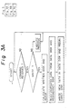
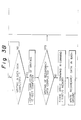
- Fig. 3 is a flow chart showing operation of the device illustrated in Fig. 2.
- microprocessor 3 causes data to be read from data blocks of writing-data disk units and data blocks of redundancy-data disk units in accordance with a predetermined data arraying form.
- ECC engine 5 is activated under the control of microprocessor 3 and a command to read old data used for the purpose of computing redundancy data is issued to channel controllers 8a and 8e to which data disk unit 9a and redundancy data disk unit 9e are respectively connected.
- microprocessor 3 informs host computer 1 of the completion of data writing operation prior to the completion of writing the new redundancy data. Subsequently, if the writing of the redundancy data is not yet completed, microprocessor 3 causes such a writing operation to be continued as a background process.
- command/status memory 14 Information as to which block data is to be written in is stored in command/status memory 14 for the preparation of abnormality of the power source as well as the system. Even if an abnormality occurs in the power source or the system, redundancy data may be generated and written in a redundancy disk unit at the time of system restart by data from other disk units of the redundancy group in accordance with the information stored in command/status memory 14 backed up by memory back-up mechanism 16, whereby the writing operation may be completed. The information on command/status memory 14 is cancelled when a redundancy data writing process is completed. It is to be noted that, if command/status memory 14 becomes full, the writing of redundancy data is completed prior to other processes.
- information as to which block data is to be written in is stored in command/status memory 14.
- information as well as redundancy data may be stored in memory 14.
- redundancy data may be directly written in a redundancy disk unit at the time of system restart based on the information stored in command/status memory 14 and it is unnecessary to generate redundancy data based on data from other disk units of the redundancy group as in the above-described embodiment.
- an array-type recording device which has a plurality of disk units arranged in an array for storing and reproducing data for a computer system, the array-type recording device having redundancy providing means for providing redundancy data for data to be written by a computer into the array-type recording device and being capable of reporting to the computer the completion of data writing operation prior to the completion of writing redundancy data generated by the redundancy providing means.
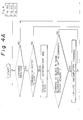
- Fig. 4 is a flow chart showing other operation performed in the device shown in Fig. 2.
- microprocessor 3 causes the command to be stored in command/status memory 14.
- microprocessor 3 reports to host computer 1 the completion of data writing operation. Subsequently, microprocessor 3 causes data to be written into a disk unit in accordance with the command as a background process.
- command/status memory 14 In this operation, task execution status which is necessary for writing data and status information sent from a disk unit are stored in command/status memory 14 in preparation for a power source failure or a system error. Should any abnormality occur in the power source or the system, the writing of data into a disk unit may be actually completed after a system restart in accordance with information stored in a cache 15 and command/status memory 14 backed up by memory back-up mechanism 16. The information stored in command/status memory 14 is cancelled upon completion of writing all data.
- command/status memory 14 becomes full, the writing of data may be actually completed prior to other processes.
- FIFO may be used alternatively.
- command/status memory 14 upon receiving a command from host computer 1, it is decided if writing command information in a block of the same redundancy group as the read block is included in command/status memory 14, and if such information is decided to be included in memory 14, the writing of such information is actually completed before other processes.
- an array-type recording device having a plurality of disk units arranged in an array for storing and reproducing data in a computer system, the array-type recording device including a redundancy providing means for providing redundancy and a non-volatile memory.
- an array-type recording device having a non-volatile memory for storing commands from a computer system and internal processing state of the array-type recording device, wherein, when any abnormality occurs in the array-type recording device, a command from the computer system may be executed again or data may be reconstructed in accordance with the information stored in the non-volatile memory.
- the non-volatile memory may comprise a RAM backed up by a secondary power source such as a battery, thereby enabling a part of RAM memories in the recording device can be utilized as the non-volatile memory. That is, no additional non-volatile memory will be required, and the disk drive device can be fabricated inexpensively and easily.
- a secondary power source such as a battery
- command/status memory 14 and cache 15 can be also constituted with normal non-volatile memories such as EEPROMs.
- command/status memory 14 cache 15 and memory 14 are separate in the embodiment shown in Fig. 2, they can be made of sections of one or more memories.
- RAID levels 4 and 5 when data is written, old data to be updated is read out of a data disk unit and a redundancy disk unit, and, after the generation of new redundancy data, new data and the new redundancy data are written.
- old data to be updated is read out of a data disk unit and a redundancy disk unit, and, after the generation of new redundancy data, new data and the new redundancy data are written.
- new redundancy data can be possibly generated faster if data is read from a disk unit of the same redundancy group in which no data is written.
- the redundancy group includes (N + 1) disk units and a piece of data is written in M disk units
- ECC engine 5 can generate new redundancy data.
- redundancy data As another method of generating redundancy data, it is possible to generate such data by reading data from disk units of the same redundancy group in which no data is written. In this case, data are read out of (N - M) disk units.
- microprocessor 3 in control section 23 compares (M + 1) with (N - M) and executes a processing based on one of the two methods by which data is written in fewer number of disk units.
- an array-type recording device having a control section capable of altering disk units of which data are to be read out first for generating redundancy data depending on the number of writing disk units at the time of data writing operation.
- channel 10a and channel controller 8a constitute the first data transfer means
- channel 10b and channel controller 8b constitute the second data transfer means.
- Disk unit 9a is connected to two channels 10a and 10b. If access to the disk unit through one of the channels 10a becomes error, such access is switched to the other of the channels 10b, thereby enabling access to be completed. In this way, the occurrence of errors in channels may be avoided.
Landscapes
- Engineering & Computer Science (AREA)
- Theoretical Computer Science (AREA)
- Quality & Reliability (AREA)
- Physics & Mathematics (AREA)
- General Engineering & Computer Science (AREA)
- General Physics & Mathematics (AREA)
- Techniques For Improving Reliability Of Storages (AREA)
- Signal Processing For Digital Recording And Reproducing (AREA)
Applications Claiming Priority (3)
| Application Number | Priority Date | Filing Date | Title |
|---|---|---|---|
| JP7890491 | 1991-04-11 | ||
| JP3078904A JP2743606B2 (ja) | 1991-04-11 | 1991-04-11 | アレイ型記録装置 |
| EP92106224A EP0508441B1 (fr) | 1991-04-11 | 1992-04-10 | Appareil d'enregistrement |
Related Parent Applications (1)
| Application Number | Title | Priority Date | Filing Date |
|---|---|---|---|
| EP92106224A Division EP0508441B1 (fr) | 1991-04-11 | 1992-04-10 | Appareil d'enregistrement |
Publications (2)
| Publication Number | Publication Date |
|---|---|
| EP0936534A2 true EP0936534A2 (fr) | 1999-08-18 |
| EP0936534A3 EP0936534A3 (fr) | 2003-08-13 |
Family
ID=13674820
Family Applications (2)
| Application Number | Title | Priority Date | Filing Date |
|---|---|---|---|
| EP92106224A Expired - Lifetime EP0508441B1 (fr) | 1991-04-11 | 1992-04-10 | Appareil d'enregistrement |
| EP99108417A Withdrawn EP0936534A3 (fr) | 1991-04-11 | 1992-04-10 | Appareil d'enregistrement |
Family Applications Before (1)
| Application Number | Title | Priority Date | Filing Date |
|---|---|---|---|
| EP92106224A Expired - Lifetime EP0508441B1 (fr) | 1991-04-11 | 1992-04-10 | Appareil d'enregistrement |
Country Status (5)
| Country | Link |
|---|---|
| US (3) | US5655150A (fr) |
| EP (2) | EP0508441B1 (fr) |
| JP (1) | JP2743606B2 (fr) |
| CA (1) | CA2065832C (fr) |
| DE (1) | DE69230351T2 (fr) |
Cited By (2)
| Publication number | Priority date | Publication date | Assignee | Title |
|---|---|---|---|---|
| EP1168173A3 (fr) * | 2000-06-29 | 2004-09-22 | Snap Appliance, Inc. | Dispositif de stockage insensible aux défaillances disposant d'une antémémoire |
| EP1770492A3 (fr) * | 2005-08-01 | 2007-05-09 | Infortrend Technology, Inc. | Une méthode pour améliorer l'efficacité d'écriture de données et sous-système de stockage et système correspondant |
Families Citing this family (67)
| Publication number | Priority date | Publication date | Assignee | Title |
|---|---|---|---|---|
| JP2743606B2 (ja) * | 1991-04-11 | 1998-04-22 | 三菱電機株式会社 | アレイ型記録装置 |
| US5315602A (en) * | 1992-08-12 | 1994-05-24 | Digital Equipment Corporation | Optimized stripe detection for redundant arrays of disk drives |
| JP3183719B2 (ja) * | 1992-08-26 | 2001-07-09 | 三菱電機株式会社 | アレイ型記録装置 |
| GB2270791B (en) * | 1992-09-21 | 1996-07-17 | Grass Valley Group | Disk-based digital video recorder |
| JP3181398B2 (ja) * | 1992-10-06 | 2001-07-03 | 三菱電機株式会社 | アレイ型記録装置 |
| US5579474A (en) | 1992-12-28 | 1996-11-26 | Hitachi, Ltd. | Disk array system and its control method |
| US5758057A (en) * | 1995-06-21 | 1998-05-26 | Mitsubishi Denki Kabushiki Kaisha | Multi-media storage system |
| US6018778A (en) * | 1996-05-03 | 2000-01-25 | Netcell Corporation | Disk array controller for reading/writing striped data using a single address counter for synchronously transferring data between data ports and buffer memory |
| US5922077A (en) * | 1996-11-14 | 1999-07-13 | Data General Corporation | Fail-over switching system |
| US6292878B1 (en) | 1996-12-12 | 2001-09-18 | Matsushita Electric Industrial Co., Ltd. | Data recorder and method of access to data recorder |
| DE69804523T2 (de) * | 1997-02-03 | 2002-07-18 | Matsushita Electric Industrial Co., Ltd. | Datenrecorder und Verfahren zum Zugriff auf einen Datenrecorder |
| JP3474110B2 (ja) | 1997-08-25 | 2003-12-08 | 株式会社リコー | 光ディスク記録再生装置と光ディスク記録再生方法とコンピュータ読み取り可能な記録媒体 |
| FR2771225B1 (fr) * | 1997-11-20 | 1999-12-24 | Bull Sa | Protection contre les defauts electriques dans un systeme de stockage de donnees |
| JP3184171B2 (ja) * | 1998-02-26 | 2001-07-09 | 日本電気株式会社 | ディスクアレイ装置、そのエラー制御方法、ならびにその制御プログラムを記録した記録媒体 |
| US6170063B1 (en) | 1998-03-07 | 2001-01-02 | Hewlett-Packard Company | Method for performing atomic, concurrent read and write operations on multiple storage devices |
| JP4325817B2 (ja) | 1999-04-05 | 2009-09-02 | 株式会社日立製作所 | ディスクアレイ装置 |
| US6493772B1 (en) * | 1999-08-23 | 2002-12-10 | International Business Machines Corporation | System and method with guaranteed maximum command response time |
| US6629273B1 (en) * | 2000-01-24 | 2003-09-30 | Hewlett-Packard Development Company, L.P. | Detection of silent data corruption in a storage system |
| US6606629B1 (en) | 2000-05-17 | 2003-08-12 | Lsi Logic Corporation | Data structures containing sequence and revision number metadata used in mass storage data integrity-assuring technique |
| US6553511B1 (en) * | 2000-05-17 | 2003-04-22 | Lsi Logic Corporation | Mass storage data integrity-assuring technique utilizing sequence and revision number metadata |
| US6898783B1 (en) * | 2000-08-03 | 2005-05-24 | International Business Machines Corporation | Object oriented based methodology for modeling business functionality for enabling implementation in a web based environment |
| US6684388B1 (en) | 2000-08-22 | 2004-01-27 | International Business Machines Corporation | Method for generating platform independent, language specific computer code |
| US7171455B1 (en) | 2000-08-22 | 2007-01-30 | International Business Machines Corporation | Object oriented based, business class methodology for generating quasi-static web pages at periodic intervals |
| JP2002073954A (ja) * | 2000-08-24 | 2002-03-12 | Nec Corp | コンピュータ周辺装置の販売促進システムおよび販売促進方法 |
| US6853994B1 (en) | 2000-08-30 | 2005-02-08 | International Business Machines Corporation | Object oriented based, business class methodology for performing data metric analysis |
| US6928590B2 (en) * | 2001-12-14 | 2005-08-09 | Matrix Semiconductor, Inc. | Memory device and method for storing bits in non-adjacent storage locations in a memory array |
| US7480807B2 (en) | 2002-02-05 | 2009-01-20 | Asaca Corporation | Data storage system |
| US7373559B2 (en) * | 2003-09-11 | 2008-05-13 | Copan Systems, Inc. | Method and system for proactive drive replacement for high availability storage systems |
| US7302603B2 (en) * | 2003-11-20 | 2007-11-27 | International Business Machines Corporation | Host-initiated data reconstruction for improved RAID read operations |
| JP4401788B2 (ja) * | 2004-01-06 | 2010-01-20 | 株式会社日立製作所 | ストレージ制御装置 |
| JP2005301419A (ja) * | 2004-04-07 | 2005-10-27 | Hitachi Ltd | ディスクアレイ装置およびそのデータ処理方法 |
| US20050283654A1 (en) * | 2004-05-24 | 2005-12-22 | Sun Microsystems, Inc. | Method and apparatus for decreasing failed disk reconstruction time in a raid data storage system |
| US20050283682A1 (en) * | 2004-06-18 | 2005-12-22 | Hitachi, Ltd. | Method for data protection in disk array systems |
| JP2006040044A (ja) * | 2004-07-28 | 2006-02-09 | Sony Corp | データ蓄積装置及びそのデータ蓄積方法 |
| JP2006073045A (ja) * | 2004-08-31 | 2006-03-16 | Hitachi Ltd | 記憶装置システム |
| US20060195704A1 (en) * | 2005-01-27 | 2006-08-31 | Hewlett-Packard Development Company, L.P. | Disk array encryption element |
| US7437080B2 (en) * | 2005-02-03 | 2008-10-14 | Stratalight Communications, Inc. | Optical transmission system having optimized filter wavelength offsets |
| US7543215B2 (en) * | 2005-02-14 | 2009-06-02 | Mediatek Inc. | Integrated apparatus for multi-standard optical storage media |
| JP2006251960A (ja) * | 2005-03-09 | 2006-09-21 | Hitachi Ltd | ストレージ装置 |
| US8159925B2 (en) * | 2005-08-05 | 2012-04-17 | The Invention Science Fund I, Llc | Limited use memory device with associated information |
| US8121016B2 (en) * | 2005-05-09 | 2012-02-21 | The Invention Science Fund I, Llc | Rotation responsive disk activation and deactivation mechanisms |
| US8099608B2 (en) * | 2005-05-09 | 2012-01-17 | The Invention Science Fund I, Llc | Limited use data storing device |
| US9396752B2 (en) * | 2005-08-05 | 2016-07-19 | Searete Llc | Memory device activation and deactivation |
| US7565596B2 (en) * | 2005-09-09 | 2009-07-21 | Searete Llc | Data recovery systems |
| US7916615B2 (en) * | 2005-06-09 | 2011-03-29 | The Invention Science Fund I, Llc | Method and system for rotational control of data storage devices |
| US20110181981A1 (en) * | 2005-05-09 | 2011-07-28 | Searete Llc, A Limited Liability Corporation Of The State Of Delaware | Method and system for rotational control of data storage devices |
| US8140745B2 (en) * | 2005-09-09 | 2012-03-20 | The Invention Science Fund I, Llc | Data retrieval methods |
| US8462605B2 (en) | 2005-05-09 | 2013-06-11 | The Invention Science Fund I, Llc | Method of manufacturing a limited use data storing device |
| US7916592B2 (en) * | 2005-05-09 | 2011-03-29 | The Invention Science Fund I, Llc | Fluid mediated disk activation and deactivation mechanisms |
| US8218262B2 (en) * | 2005-05-09 | 2012-07-10 | The Invention Science Fund I, Llc | Method of manufacturing a limited use data storing device including structured data and primary and secondary read-support information |
| US8220014B2 (en) * | 2005-05-09 | 2012-07-10 | The Invention Science Fund I, Llc | Modifiable memory devices having limited expected lifetime |
| US7596073B2 (en) | 2005-05-09 | 2009-09-29 | Searete Llc | Method and system for fluid mediated disk activation and deactivation |
| US7747788B2 (en) * | 2005-06-30 | 2010-06-29 | Intel Corporation | Hardware oriented target-side native command queuing tag management |
| US7805543B2 (en) * | 2005-06-30 | 2010-09-28 | Intel Corporation | Hardware oriented host-side native command queuing tag management |
| US8135869B2 (en) * | 2005-06-30 | 2012-03-13 | Intel Corporation | Task scheduling to devices with same connection address |
| US7970953B2 (en) * | 2005-06-30 | 2011-06-28 | Intel Corporation | Serial ATA port addressing |
| US7676604B2 (en) * | 2005-11-22 | 2010-03-09 | Intel Corporation | Task context direct indexing in a protocol engine |
| KR100744122B1 (ko) * | 2006-01-12 | 2007-08-01 | 삼성전자주식회사 | 하이브리드 하드디스크 드라이브의 제어 방법, 이에 적합한기록 매체 그리고 이에 적합한 장치 |
| US8264928B2 (en) * | 2006-06-19 | 2012-09-11 | The Invention Science Fund I, Llc | Method and system for fluid mediated disk activation and deactivation |
| JP2008134830A (ja) | 2006-11-28 | 2008-06-12 | Hitachi Ltd | 節電機能と診断機能の両方を備えたストレージシステム |
| GB2455772A (en) * | 2007-12-20 | 2009-06-24 | Symbian Software Ltd | Early reporting of commands to a peripheral device |
| US20090187413A1 (en) * | 2008-01-18 | 2009-07-23 | Timothy Abels | Service delivery platform for automated and remote information technology management |
| JP5521816B2 (ja) * | 2010-06-18 | 2014-06-18 | 富士通株式会社 | 記憶装置、制御装置および記憶装置の制御方法 |
| JP5891890B2 (ja) | 2012-03-26 | 2016-03-23 | 富士通株式会社 | ストレージシステム、ストレージ装置およびデータ復元方法 |
| CN109947374B (zh) * | 2019-04-01 | 2022-07-22 | 江苏华存电子科技有限公司 | 一种闪存主控模块中写入错误的冗余备援保护方法 |
| US11150839B2 (en) | 2019-12-19 | 2021-10-19 | Western Digital Technologies, Inc. | Host and method for interleaving data in a storage system for enhanced quality of service |
| US11221950B2 (en) | 2019-12-19 | 2022-01-11 | Western Digital Technologies, Inc. | Storage system and method for interleaving data for enhanced quality of service |
Family Cites Families (43)
| Publication number | Priority date | Publication date | Assignee | Title |
|---|---|---|---|---|
| US4268905A (en) * | 1978-12-14 | 1981-05-19 | Sperry Rand Corporation | Autonomous fault diagnosis for disk drive using an internal microprocessor |
| US4636946A (en) * | 1982-02-24 | 1987-01-13 | International Business Machines Corporation | Method and apparatus for grouping asynchronous recording operations |
| US4638425A (en) * | 1982-09-29 | 1987-01-20 | International Business Machines Corporation | Peripheral data storage having access controls with error recovery |
| WO1984002409A1 (fr) * | 1982-12-09 | 1984-06-21 | Sequoia Systems Inc | Systeme de sauvegarde de memoire |
| JPS60179863A (ja) * | 1984-02-27 | 1985-09-13 | Fujitsu Ltd | 入出力システムの再試行制御方法 |
| US4916605A (en) * | 1984-03-27 | 1990-04-10 | International Business Machines Corporation | Fast write operations |
| JPS61275929A (ja) * | 1985-05-08 | 1986-12-06 | Panafacom Ltd | バツクアツプ処理方式 |
| JPH0754947B2 (ja) * | 1985-10-16 | 1995-06-07 | 株式会社日立製作所 | 予備系監視方式 |
| US4761785B1 (en) * | 1986-06-12 | 1996-03-12 | Ibm | Parity spreading to enhance storage access |
| JPS63163912A (ja) * | 1986-12-26 | 1988-07-07 | Toshiba Corp | マイクロコンピユ−タシステム |
| JPS63216150A (ja) * | 1987-03-05 | 1988-09-08 | Fujitsu Ltd | 記憶装置 |
| JPS63279318A (ja) * | 1987-05-11 | 1988-11-16 | Nec Corp | 磁気ディスク装置 |
| CA1296103C (fr) * | 1987-06-02 | 1992-02-18 | Theodore Jay Goodlander | Systeme de stockage rapide de grande capacite a correction des erreurs insensible aux defaillances |
| JPS6464047A (en) * | 1987-09-04 | 1989-03-09 | Fujitsu Ltd | Disk cache control system |
| JPH0731640B2 (ja) * | 1987-09-08 | 1995-04-10 | 富士通株式会社 | ディスクアクセス制御方式 |
| JPH01106247A (ja) * | 1987-10-20 | 1989-04-24 | Nec Corp | メモリカード |
| US4993030A (en) * | 1988-04-22 | 1991-02-12 | Amdahl Corporation | File system for a plurality of storage classes |
| US4914656A (en) * | 1988-06-28 | 1990-04-03 | Storage Technology Corporation | Disk drive memory |
| JPH029063A (ja) * | 1988-06-28 | 1990-01-12 | Nec Corp | ディスク制御装置 |
| JP2567922B2 (ja) * | 1988-08-30 | 1996-12-25 | 株式会社日立製作所 | パス制御方式 |
| JPH0287223A (ja) * | 1988-09-22 | 1990-03-28 | Nec Corp | ディスク装置の制御方式 |
| AU630635B2 (en) * | 1988-11-14 | 1992-11-05 | Emc Corporation | Arrayed disk drive system and method |
| US5148432A (en) * | 1988-11-14 | 1992-09-15 | Array Technology Corporation | Arrayed disk drive system and method |
| FR2643993B1 (fr) * | 1989-03-03 | 1991-05-17 | Bull Sa | Procede pour remplacer des modules memoire dans un systeme informatique et systeme informatique pour la mise en oeuvre du procede |
| JPH02291011A (ja) * | 1989-04-28 | 1990-11-30 | Fujitsu Ltd | 記憶装置 |
| US5249279A (en) * | 1989-11-03 | 1993-09-28 | Compaq Computer Corporation | Method for controlling disk array operations by receiving logical disk requests and translating the requests to multiple physical disk specific commands |
| US5101492A (en) * | 1989-11-03 | 1992-03-31 | Compaq Computer Corporation | Data redundancy and recovery protection |
| US5402428A (en) * | 1989-12-25 | 1995-03-28 | Hitachi, Ltd. | Array disk subsystem |
| JPH0833864B2 (ja) * | 1990-01-30 | 1996-03-29 | 富士通株式会社 | データ保全方式 |
| US5233618A (en) * | 1990-03-02 | 1993-08-03 | Micro Technology, Inc. | Data correcting applicable to redundant arrays of independent disks |
| US5134619A (en) * | 1990-04-06 | 1992-07-28 | Sf2 Corporation | Failure-tolerant mass storage system |
| US5088081A (en) * | 1990-03-28 | 1992-02-11 | Prime Computer, Inc. | Method and apparatus for improved disk access |
| JPH0731582B2 (ja) * | 1990-06-21 | 1995-04-10 | インターナショナル・ビジネス・マシーンズ・コーポレイション | パリティ保護データを回復するための方法および装置 |
| US5210860A (en) * | 1990-07-20 | 1993-05-11 | Compaq Computer Corporation | Intelligent disk array controller |
| EP0784272B1 (fr) * | 1990-09-20 | 2000-05-24 | Fujitsu Limited | Contrôleur d'entrée/sortie |
| US5375128A (en) * | 1990-10-18 | 1994-12-20 | Ibm Corporation (International Business Machines Corporation) | Fast updating of DASD arrays using selective shadow writing of parity and data blocks, tracks, or cylinders |
| US5146588A (en) * | 1990-11-26 | 1992-09-08 | Storage Technology Corporation | Redundancy accumulator for disk drive array memory |
| US5235601A (en) * | 1990-12-21 | 1993-08-10 | Array Technology Corporation | On-line restoration of redundancy information in a redundant array system |
| US5274799A (en) * | 1991-01-04 | 1993-12-28 | Array Technology Corporation | Storage device array architecture with copyback cache |
| US5239640A (en) * | 1991-02-01 | 1993-08-24 | International Business Machines Corporation | Data storage system and method including data and checksum write staging storage |
| US5271012A (en) * | 1991-02-11 | 1993-12-14 | International Business Machines Corporation | Method and means for encoding and rebuilding data contents of up to two unavailable DASDs in an array of DASDs |
| US5345565A (en) * | 1991-03-13 | 1994-09-06 | Ncr Corporation | Multiple configuration data path architecture for a disk array controller |
| JP2743606B2 (ja) * | 1991-04-11 | 1998-04-22 | 三菱電機株式会社 | アレイ型記録装置 |
-
1991
- 1991-04-11 JP JP3078904A patent/JP2743606B2/ja not_active Expired - Fee Related
-
1992
- 1992-04-10 EP EP92106224A patent/EP0508441B1/fr not_active Expired - Lifetime
- 1992-04-10 CA CA002065832A patent/CA2065832C/fr not_active Expired - Fee Related
- 1992-04-10 DE DE69230351T patent/DE69230351T2/de not_active Expired - Fee Related
- 1992-04-10 EP EP99108417A patent/EP0936534A3/fr not_active Withdrawn
-
1995
- 1995-02-16 US US08/390,820 patent/US5655150A/en not_active Expired - Fee Related
-
1997
- 1997-01-24 US US08/788,989 patent/US5878203A/en not_active Expired - Fee Related
- 1997-02-24 US US08/805,221 patent/US5862406A/en not_active Expired - Fee Related
Cited By (3)
| Publication number | Priority date | Publication date | Assignee | Title |
|---|---|---|---|---|
| EP1168173A3 (fr) * | 2000-06-29 | 2004-09-22 | Snap Appliance, Inc. | Dispositif de stockage insensible aux défaillances disposant d'une antémémoire |
| EP1770492A3 (fr) * | 2005-08-01 | 2007-05-09 | Infortrend Technology, Inc. | Une méthode pour améliorer l'efficacité d'écriture de données et sous-système de stockage et système correspondant |
| US7516268B2 (en) | 2005-08-01 | 2009-04-07 | Infortrend Technology, Inc. | Method for improving writing data efficiency and storage subsystem and system implementing the same |
Also Published As
| Publication number | Publication date |
|---|---|
| EP0508441A3 (fr) | 1995-05-03 |
| US5878203A (en) | 1999-03-02 |
| DE69230351T2 (de) | 2000-07-06 |
| CA2065832C (fr) | 1999-08-17 |
| US5655150A (en) | 1997-08-05 |
| EP0508441B1 (fr) | 1999-12-01 |
| CA2065832A1 (fr) | 1992-10-12 |
| EP0508441A2 (fr) | 1992-10-14 |
| US5862406A (en) | 1999-01-19 |
| DE69230351D1 (de) | 2000-01-05 |
| EP0936534A3 (fr) | 2003-08-13 |
| JPH04312146A (ja) | 1992-11-04 |
| JP2743606B2 (ja) | 1998-04-22 |
Similar Documents
| Publication | Publication Date | Title |
|---|---|---|
| EP0936534A2 (fr) | Appareil d'enregistrement | |
| US5566316A (en) | Method and apparatus for hierarchical management of data storage elements in an array storage device | |
| US4989205A (en) | Disk drive memory | |
| EP0515499B1 (fr) | Memoire d'unites a disques | |
| US4914656A (en) | Disk drive memory | |
| US4989206A (en) | Disk drive memory | |
| JP3226370B2 (ja) | 高可用度ディスク配列に関する改善 | |
| US6000039A (en) | Data reconstruction method and system wherein timing of data reconstruction is controlled in accordance with conditions when a failure occurs | |
| US6154853A (en) | Method and apparatus for dynamic sparing in a RAID storage system | |
| US5889934A (en) | Data validation system for a group of data storage disks | |
| JP3742494B2 (ja) | 大容量記憶装置 | |
| CA2089836C (fr) | Piles de disques a acces rapide | |
| JP2006079219A (ja) | ディスクアレイ制御装置およびディスクアレイ制御方法 | |
| JP2913840B2 (ja) | 集合ディスク装置 | |
| EP0559488B1 (fr) | Manipulation de données dans un système à processeur pour commander l'accès à une pluralité de disques de stockage de données | |
| CA2250560C (fr) | Dispositif d'enregistrement a duree d'enregistrement de donnees breve | |
| JP2778268B2 (ja) | 記録媒体制御装置 | |
| JP2001034424A (ja) | ディスクアレイ制御装置 |
Legal Events
| Date | Code | Title | Description |
|---|---|---|---|
| PUAI | Public reference made under article 153(3) epc to a published international application that has entered the european phase |
Free format text: ORIGINAL CODE: 0009012 |
|
| 17P | Request for examination filed |
Effective date: 19990429 |
|
| AC | Divisional application: reference to earlier application |
Ref document number: 508441 Country of ref document: EP |
|
| AK | Designated contracting states |
Kind code of ref document: A2 Designated state(s): DE FR GB |
|
| PUAL | Search report despatched |
Free format text: ORIGINAL CODE: 0009013 |
|
| AK | Designated contracting states |
Designated state(s): DE FR GB |
|
| STAA | Information on the status of an ep patent application or granted ep patent |
Free format text: STATUS: THE APPLICATION IS DEEMED TO BE WITHDRAWN |
|
| 18D | Application deemed to be withdrawn |
Effective date: 20040214 |