EP0936662A2 - Dispositif pour le traitement thermique de semiconducteur avec système de refroidissement par recirculation de gaz d'échappement - Google Patents
Dispositif pour le traitement thermique de semiconducteur avec système de refroidissement par recirculation de gaz d'échappement Download PDFInfo
- Publication number
- EP0936662A2 EP0936662A2 EP99300910A EP99300910A EP0936662A2 EP 0936662 A2 EP0936662 A2 EP 0936662A2 EP 99300910 A EP99300910 A EP 99300910A EP 99300910 A EP99300910 A EP 99300910A EP 0936662 A2 EP0936662 A2 EP 0936662A2
- Authority
- EP
- European Patent Office
- Prior art keywords
- gas
- cooling
- chilled
- inlet
- furnace
- Prior art date
- Legal status (The legal status is an assumption and is not a legal conclusion. Google has not performed a legal analysis and makes no representation as to the accuracy of the status listed.)
- Withdrawn
Links
Images

Classifications
-
- H—ELECTRICITY
- H10—SEMICONDUCTOR DEVICES; ELECTRIC SOLID-STATE DEVICES NOT OTHERWISE PROVIDED FOR
- H10P—GENERIC PROCESSES OR APPARATUS FOR THE MANUFACTURE OR TREATMENT OF DEVICES COVERED BY CLASS H10
- H10P95/00—Generic processes or apparatus for manufacture or treatments not covered by the other groups of this subclass
-
- H—ELECTRICITY
- H10—SEMICONDUCTOR DEVICES; ELECTRIC SOLID-STATE DEVICES NOT OTHERWISE PROVIDED FOR
- H10P—GENERIC PROCESSES OR APPARATUS FOR THE MANUFACTURE OR TREATMENT OF DEVICES COVERED BY CLASS H10
- H10P72/00—Handling or holding of wafers, substrates or devices during manufacture or treatment thereof
- H10P72/04—Apparatus for manufacture or treatment
- H10P72/0431—Apparatus for thermal treatment
- H10P72/0434—Apparatus for thermal treatment mainly by convection
Definitions
- This invention relates to an improved thermal processing apparatus and process for heat treatment of semiconductor and glass water substrates and the like.
- Heat treatment devices have been used to form diffusion layers or form silicon oxide or nitride films on semiconductor or glass substrates in the manufacture of electronic devices. These substrates are typically thin wafers made of silicon or other semiconductor materials. The description of the device hereinafter will be provided in reference to wafer substrates, it being understood that the apparatus is equally suitable for treating any thin glass or semiconductor sheets, and treatment of any or all of these materials are considered to be within the scope of this invention.
- These devices provide the desired heat treatment by heating the wafers in a reactor or heating chamber while introducing inert or reactive gases into the chamber. These heating chambers are surrounded by heating elements enclosed within an insulated shell. In order to treat large numbers of wafers in a single heat treatment operation, it is conventional to support the wafers, one above the other in a parallel orientation, in a water boat. This combination is referred to hereinafter as a water stack.
- Vertical furnaces generally have the furnace and coaxial water boat aligned along a vertical axis.
- the water boat loaded with wafers to be treated is raised into the furnace through a bottom opening before the treatment cycle and lowered from the furnace after treatment.
- a preferred vertical furnace designed to reduce particulate contaminants by eliminating gas eddy areas in the reaction chamber is described in U.S. Patent No. 5,320,680.
- a vertical rapid cooling furnace for treating semiconductor wafers with self contained gas chilling and recycling comprises a hot wall reaction tube positioned within a cylindrical array of heating coils. Space between the hot wall reaction tube and said array of heating coils provides a cooling gas passageway therebetween.
- the cooling gas passageway has an inlet and an outlet, a chilled gas inlet communicating with the inlet of the cooling gas passageway and a heated gas outlet communicating with the outlet of the cooling gas passageway.
- the furnace includes a heat exchanger having a hot gas inlet and a chilled gas outlet, the hot gas inlet thereof communicating with said heated gas outlet, and the chilled gas outlet communicating with said cooling gas passageway inlet. With this system, heated gas from the cooling gas passageway can be chilled to remove heat therefrom and returned to the cooling gas passageway to remove heat from the furnace.
- the furnace preferably includes a fan placed between the chilled gas outlet and the cooling gas passageway inlet.
- the heating coils of the furnace are surrounded by a cylindrical tube of insulation, a cooling air supply shell surrounds the insulation and is spaced therefrom to provide a cooling air supply plenum therebetween.
- a cooling air supply plenum communicates with said chilled gas outlet of said heat exchanger.
- At least one circulating water temperature regulating coil is positioned in a heat conducting relationship with the exterior surface of the cylindrical tube or shell of insulation to regulate the outer surface temperature of the cylinder of insulation.
- a cylindrical shell is positioned between the circulating water temperature regulating coil and the cooling air supply shell and is spaced therefrom, the space between the cylindrical shell and the cooling air supply shell comprising the cooling air supply plenum.
- An insulating cap is preferably positioned adjacent the top of the cylinder of insulation, the space therebetween comprising the outlet of the cooling gas passageway.
- the furnace includes a heat exchanger system enclosed within insulated walls, the heat exchanger system comprising an insulated inlet plenum for receiving heated gas from the cooling gas passageway outlet and a chilled gas outlet plenum.
- the heat exchanger is positioned for communication with the inlet plenum and with the chilled gas outlet plenum whereby heat in the gases passing from the inlet plenum to the chilled gas outlet plenum is removed by the heat exchanger.
- a return chilled gas plenum communicates with the chilled gas outlet plenum and the inlet of the cooling gas passageway, and an opening is present between the chilled gas outlet plenum and the return chilled gas plenum.
- a fan is positioned adjacent to or in communication with the opening for moving gas from the chilled gas outlet plenum to the return chilled gas plenum.
- At least one heated gas valve is placed between the cooling gas passageway outlet and the heat exchanger, whereby communication between the cooling gas passageway outlet and the heat exchanger can be terminated by closure of the heated gas valve and can be opened by opening the heated gas valve.
- At least one chilled air first valve is placed between the return chilled gas plenum and the cooling gas passageway inlet, whereby communication between the return chilled gas plenum and the cooling gas passageway inlet can be terminated when the chilled gas valve is closed and communication between the return chilled gas plenum and the cooling gas passageway inlet can be opened when the chilled gas valve is open.
- at least one heated gas valve is also placed between the cooling gas passageway outlet and the heat exchanger, whereby communication between the cooling gas passageway outlet and the heat exchanger can be terminated by closure of the heated gas valve and can be opened by opening the heated gas valve.
- a process for cooling the vertical rapid cooling furnace described above for treating semiconductor wafers comprises removing heated air from the cooling gas passageway outlet, passing the heated gas through a heat exchanger to form chilled gas, returning the chilled gas to the cooling gas passageway inlet, passing the chilled gas through the cooling gas passageway to remove heat from the furnace, forming heated gas, and returning the heated to the heat exchanger for heat removal therefrom.
- the upper part of the furnace is connected to a furnace exhaust gas conduit or duct which, in turn, communicates with the central air exhaust system of the facility having an exhaust system.
- a duct control valve is provided which seals the top of the reactor and terminates the exhaust of cooling gases during the heating and reaction cycle. During the cooling cycle, this duct control valve is opened to permit cooling air to sweep through the reactor, exiting the reactor to enter the exhaust system.
- the furnace exhaust gas conduit or duct can be provided with a conventional heat exchanger to remove heat from the exhaust during the cooling cycle. This was found necessary for some systems because of the presence of thermally unstable seals or other components in the waste gas ducts.
- the rapid vertical processor with the integral recirculating heater element exhaust cooling system of this invention is an improved embodiment suitable for use in facilities which do not have facility waste gas exhaust systems or which have severely limited exhaust capacities, or in facilities where the exhaust system includes thermally unstable, organic polymer components such as seals and gaskets in the exhaust or fan system. It removes heated gases, removes heat therefrom to form chilled gases, and returns the chilled gases to remove heat from the furnace or thermal reactor.
- the gases described for the cooling of the reactor or furnace are interchangeably described as air or gas.
- Air is generally suitable, but in certain applications, another gas such as nitrogen might be employed, and the invention is intended to include the use of any gas which would be suitable for cooling the system, for being chilled, and for being recycled in as a chilled gas.
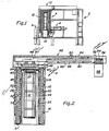
- Fig. 1 illustrates a crosssectional view of a rapid vertical processor with recirculating heater exhaust cooling system of this invention.
- the vertical reactor cabinet 2 houses the vertical reactor or processor 4 and its controls (not shown).
- the processor gas inlet conduit 6 removes spent or used processor gases from the furnace.
- the cabinet surrounding the processor has a cabinet exhaust 10 to which removes any leaking reaction gases from the system.
- the processor 4 houses the wafer boat assembly 12 supported by wafer boat pedestal 14, shown in position for wafer processing.
- Fig. 2 is a crosssectional view of portions of the furnace and exhaust cooling system of the rapid vertical processor shown in Fig. 1.
- the processor is enclosed in a cooling air supply shell 16. Inside shell 16, the processor is surrounded by a circulating water temperature regulating coil 18 which is positioned in a heat conducting relationship with the outer surface of the cylindrical thermal insulating shell, layer or tube 20, designed to maintain a controlled skin temperature for reactor.
- the interior surface of the thermal insulating shell 20 has annular cavities or receptors 22 for supporting electric resistance heating coils (not shown).
- the reaction chamber in which the wafer boat assembly 12 is positioned is enclosed within a double wall quartz isolation enclosure with an outer wall 24, an inner wall 26 and a reaction chamber top 27, all of which function to direct reaction gas flow around the wafer assembly 12 in the reactor.
- the cooling air supply shell 16 and the thermal insulation 20 define a exterior cooling air passageway for plenum 28 down which the cooling air passes in the direction shown by arrow 30, chilling the exterior of the insulation.
- the cooling air return 31 directs the air from plenum 28 to the interior cooling air plenum 32 through which the cooling gases flow in the direction of arrow 34, removing heat from the interior of the reactor.
- the interior cooling air plenum 32 is defined by the space between the outer reaction chamber wall 24 and the interior surface of the cylinder of insulation 20.
- Heat radiation and conduction from the interior of the reactor is blocked during processing by the insulating cap 38 through which cooling air outlet holes or ports 40 are positioned to allow exit of the cooling gases passing upward through plenum 32 communicating therewith.
- the cooling air flows through exhaust plenum defined by the cylindrical wall 41 (preferably of thermal insulation) to the heat exchanger 42.
- the hot air exhaust plenum 48 and heat exchanger 42 have an upper wall 44 and a lower wall 46 to direct the air flow through the heat exchanger.
- the hot air exhaust plenum 48 is defined by the lower wall 46 and thermal insulation layer 47 which prevents escape of heat into the furnace environment.
- the hot gases are passed through a conventional heat exchanger 42 with coils 50 provided with a coolant which removes the heat from the hot gases.
- the chilled air is drawn into the chilled air exhaust plenum 52 through blower inlet opening 54 by the blower wheel 56 driven by the fan motor 58.
- the blower 56 can be any conventional device for moving air from one compartment to another such as a fan using a propeller or a squirrel cage rotor with vanes, for example.
- the chilled gas flows from the wheel 56 into the chilled air return plenum 60 defined by the lower heat exchanger wall 46 and the chilled air return plenum wall 62.
- the chilled air flows into the chilled air supply plenum surrounding the top of the reactor from which it flows into the annular space of the cooling air supply plenum 64.
- the structure provides communication between each of the successive flow plenums and heat removal areas described hereinabove as the flow path of the cooling air through the system.
- the flow through the cooling air ports 40 are controlled by heated gas disc valve 66 which is actuated from the open position wherein the ports 70 therein (Fig. 3) are open to a closed position wherein the ports 70 therein are closed or from the closed to the open position by the disc valve actuator 68 which can be a conventional solenoid or other conventional disc valve actuation system.
- Fig. 3 is a cutaway top view of the recirculating exhaust cooling system showing the structure of the disc valve structure 66 with the ports 70, the heat exchanger coils 50 and conventional cooling fins 72.
- the gases in the cabinet surrounding the reactor are exhausted through conduit 10 into cabinet exhaust plenum 74 from which it is removed to a waste gas exhaust system to dispose of any leakage gases which might enter the cabinet area from the reactor during its operation.
- Fig. 4 is a schematic crosssectional view of an alternative embodiment of a rapid vertical processor with recirculating heater exhaust cooling system of this invention.
- the general assembly is similar to the assembly shown in Figs. 1-3.
- the processor furnace and cooling gas assembly is housed in a cabinet (not shown).
- Surrounding the furnace is a cylindrical outer cooling air supply shell 76.
- An inner cylindrical shell 78 concentric with outer shell 76 defines a cooling air supply plenum 80 therebetween.
- Between the inner shell 78 and insulation 84 is a space within which a spiral water cooling coil 82 is housed.
- the inner surface of the cylindrical insulation 84 has electric resistance heating coil receptors 86.
- the reaction chamber is enclosed within a double wall gas flow assembly of quartz or silicon carbide with an outer cylinder wall 88, an inner cylinder wall 90 and reaction chamber top wall 94.
- a wafer boat 96 is shown in the reaction chamber.
- heat escape from the top of the reaction chamber is blocked by insulating cap 98 which can abut or be closely spaced from the top wall 94.
- An annular hot gas exit port 100 is defined by the outer circumference or edge of the cap 98 and the annular inner insulating surface 99 supported on the upper extension of the thermal insulating cylinder 84.
- An insulating cylinder 102 above the annulus 100 and concentric therewith defines a hot air exhaust passageway leading from the reactor to the cooling gas exhaust plenum 108 defined by insulating shell 104 and lower wall 106.
- the top wall 110 of the cooling system is lined with insulation.
- Communicating with the cooling gas exhaust plenum 108 is the heat exchanger 112, which in turn, communicates with the chilled air plenum 113.
- the chilled air is drawn through an opening in the lower wall 106 through the fan blades 115 and into the chilled air return plenum 118 and from there to the chilled air supply plenum 120 communicating therewith and to the cooling air supply plenum 80.
- closure of the reactor to prevent escape of the gases during the heating phase of the reactor operation and concurrent termination of the cooling gas flow is achieved by closing the hinged heated gas shutter valve 122 and chilled gas shutter valve 124.
- Shutter valve 122 is positioned in the plenum 108 to close the opening and block the heat exchanger 112 from the plenum 108 in the heating phase and to open to permit hot air exit from plenum 108 during the cooling phase of the reactor operation.
- shutter valve 124 is positioned in chilled air supply plenum 118 to block the opening between the plenum 118 and the chilled air supply plenum 120 during the heating phase of the reactor operation and to open to permit flow of cooling air to the plenum 120 from plenum 118 during the cooling phase.
- a ring or blocks of vibrational damping material 128 which can be rubber or similar resilient material are placed around the motor rotor 126, wedged between the motor 116 and the lower wall 130. This partially isolates the motor from the gas cooling assembly.
- a series of lifting bladders 132 and 134 can be attached between the cooling assembly and the outer cabinet (not shown) to support the cooling assembly above the reaction chamber and to vibrationally isolate the cooling assembly from the furnace. This reduces stress on the furnace casing and other structures and vibrationally isolates the furnace from the motor 116 and the cooling assembly.
Applications Claiming Priority (2)
| Application Number | Priority Date | Filing Date | Title |
|---|---|---|---|
| US09/022,057 US6059567A (en) | 1998-02-10 | 1998-02-10 | Semiconductor thermal processor with recirculating heater exhaust cooling system |
| US22057 | 1998-02-10 |
Publications (2)
| Publication Number | Publication Date |
|---|---|
| EP0936662A2 true EP0936662A2 (fr) | 1999-08-18 |
| EP0936662A3 EP0936662A3 (fr) | 2003-12-17 |
Family
ID=21807594
Family Applications (1)
| Application Number | Title | Priority Date | Filing Date |
|---|---|---|---|
| EP99300910A Withdrawn EP0936662A3 (fr) | 1998-02-10 | 1999-02-09 | Dispositif pour le traitement thermique de semiconducteur avec système de refroidissement par recirculation de gaz d'échappement |
Country Status (6)
| Country | Link |
|---|---|
| US (1) | US6059567A (fr) |
| EP (1) | EP0936662A3 (fr) |
| JP (1) | JP2000003918A (fr) |
| KR (1) | KR19990072527A (fr) |
| AU (1) | AU746022B2 (fr) |
| CA (1) | CA2261391A1 (fr) |
Cited By (3)
| Publication number | Priority date | Publication date | Assignee | Title |
|---|---|---|---|---|
| EP0867916A3 (fr) * | 1997-03-28 | 2002-04-03 | Silicon Valley Group, Inc. | Appareil de traitement thermique |
| US7879693B2 (en) | 2001-06-01 | 2011-02-01 | Semiconductor Energy Laboratory Co., Ltd. | Thermal treatment equipment and method for heat-treating |
| US7974524B2 (en) | 2001-03-16 | 2011-07-05 | Semiconductor Energy Laboratory Co., Ltd. | Heat treatment apparatus and heat treatment method |
Families Citing this family (26)
| Publication number | Priority date | Publication date | Assignee | Title |
|---|---|---|---|---|
| JP2644912B2 (ja) * | 1990-08-29 | 1997-08-25 | 株式会社日立製作所 | 真空処理装置及びその運転方法 |
| US6551045B2 (en) * | 2000-11-17 | 2003-04-22 | Nikon Corporation | Wafer stage chamber |
| TW522292B (en) | 2001-02-06 | 2003-03-01 | Asml Us Inc | Inertial temperature control system and method |
| US6864466B2 (en) | 2001-03-08 | 2005-03-08 | Aviza Technology, Inc. | System and method to control radial delta temperature |
| WO2002079400A2 (fr) * | 2001-03-12 | 2002-10-10 | Novozymes Biotech, Inc. | Methodes permettant d'isoler des genes de micro-organismes |
| JP4493897B2 (ja) * | 2001-06-01 | 2010-06-30 | 株式会社半導体エネルギー研究所 | 熱処理装置及び熱処理方法 |
| DE10216786C5 (de) * | 2002-04-15 | 2009-10-15 | Ers Electronic Gmbh | Verfahren und Vorrichtung zur Konditionierung von Halbleiterwafern und/oder Hybriden |
| AU2003253873A1 (en) * | 2002-07-15 | 2004-02-02 | Aviza Technology, Inc. | Apparatus and method for backfilling a semiconductor wafer process chamber |
| US8091614B2 (en) * | 2006-11-10 | 2012-01-10 | International Business Machines Corporation | Air/fluid cooling system |
| JP5504793B2 (ja) * | 2009-09-26 | 2014-05-28 | 東京エレクトロン株式会社 | 熱処理装置及び冷却方法 |
| JP5394360B2 (ja) * | 2010-03-10 | 2014-01-22 | 東京エレクトロン株式会社 | 縦型熱処理装置およびその冷却方法 |
| JP5721219B2 (ja) * | 2010-07-09 | 2015-05-20 | 株式会社日立国際電気 | 基板処理装置、半導体装置の製造方法及び加熱装置 |
| US9513003B2 (en) * | 2010-08-16 | 2016-12-06 | Purpose Company Limited | Combustion apparatus, method for combustion control, board, combustion control system and water heater |
| US20120168143A1 (en) * | 2010-12-30 | 2012-07-05 | Poole Ventura, Inc. | Thermal Diffusion Chamber With Heat Exchanger |
| US8950470B2 (en) * | 2010-12-30 | 2015-02-10 | Poole Ventura, Inc. | Thermal diffusion chamber control device and method |
| KR102011146B1 (ko) * | 2012-12-18 | 2019-08-14 | 에스케이실트론 주식회사 | 에피택셜 웨이퍼 제조장치 |
| KR101392379B1 (ko) * | 2013-03-27 | 2014-05-12 | 주식회사 유진테크 | 기판처리장치 |
| KR101392378B1 (ko) * | 2013-03-27 | 2014-05-12 | 주식회사 유진테크 | 기판처리장치 |
| US10436516B2 (en) | 2013-08-23 | 2019-10-08 | Savannah River Nuclear Solutions, Llc | Thermal cycling device |
| US10115571B2 (en) * | 2014-06-04 | 2018-10-30 | Applied Materials, Inc. | Reagent delivery system freeze prevention heat exchanger |
| US20170191685A1 (en) * | 2015-12-30 | 2017-07-06 | Lam Research Corporation | Self-sustained in-situ thermal control apparatus |
| US20170207078A1 (en) * | 2016-01-15 | 2017-07-20 | Taiwan Semiconductor Manufacturing Co., Ltd. | Atomic layer deposition apparatus and semiconductor process |
| KR102179851B1 (ko) * | 2019-04-09 | 2020-11-17 | 주식회사 디엠에스 | 기판처리장치 및 이를 이용한 인라인 기판처리시스템 |
| CN111023841B (zh) * | 2019-12-26 | 2023-09-08 | 北京北方华创微电子装备有限公司 | 炉体冷却装置及半导体加工设备 |
| US11444053B2 (en) * | 2020-02-25 | 2022-09-13 | Yield Engineering Systems, Inc. | Batch processing oven and method |
| US11688621B2 (en) | 2020-12-10 | 2023-06-27 | Yield Engineering Systems, Inc. | Batch processing oven and operating methods |
Family Cites Families (50)
| Publication number | Priority date | Publication date | Assignee | Title |
|---|---|---|---|---|
| DE1137807B (de) * | 1961-06-09 | 1962-10-11 | Siemens Ag | Verfahren zur Herstellung von Halbleiteranordnungen durch einkristalline Abscheidung von Halbleitermaterial aus der Gasphase |
| US4062318A (en) * | 1976-11-19 | 1977-12-13 | Rca Corporation | Apparatus for chemical vapor deposition |
| US4263872A (en) * | 1980-01-31 | 1981-04-28 | Rca Corporation | Radiation heated reactor for chemical vapor deposition on substrates |
| US4339645A (en) * | 1980-07-03 | 1982-07-13 | Rca Corporation | RF Heating coil construction for stack of susceptors |
| US4363959A (en) * | 1981-08-31 | 1982-12-14 | E. R. Wagner Manufacturing Company | Stand-off for resistance wires |
| US4493089A (en) * | 1983-03-21 | 1985-01-08 | Refractory Poroducts Co. | Electric furnace insulation |
| US4695706A (en) * | 1983-12-28 | 1987-09-22 | Denkoh Co. Ltd. | Vertical furnace for heat-treating semiconductor |
| EP0164928A3 (fr) * | 1984-06-04 | 1987-07-29 | Texas Instruments Incorporated | Réacteur vertical à parois chaudes pour dépôt chimique à partir de la phase vapeur |
| JPH0758696B2 (ja) * | 1984-11-09 | 1995-06-21 | 株式会社日立製作所 | 半導体ウエハ加熱装置 |
| JPS61290713A (ja) * | 1985-06-19 | 1986-12-20 | Hitachi Ltd | 処理装置 |
| JPS62136810A (ja) * | 1985-12-11 | 1987-06-19 | Hitachi Ltd | 処理装置 |
| JPH0815144B2 (ja) * | 1986-04-18 | 1996-02-14 | 株式会社日立製作所 | 縦型処理装置 |
| US4770590A (en) * | 1986-05-16 | 1988-09-13 | Silicon Valley Group, Inc. | Method and apparatus for transferring wafers between cassettes and a boat |
| US4926793A (en) * | 1986-12-15 | 1990-05-22 | Shin-Etsu Handotai Co., Ltd. | Method of forming thin film and apparatus therefor |
| US4849608A (en) * | 1987-02-14 | 1989-07-18 | Dainippon Screen Mfg. Co., Ltd. | Apparatus for heat-treating wafers |
| JPS6451619A (en) * | 1987-08-21 | 1989-02-27 | Dainippon Screen Mfg | Heat treatment equipment for substrate |
| JPS6455821A (en) * | 1987-08-26 | 1989-03-02 | Dainippon Screen Mfg | Rapid cooling type heat treating apparatus |
| US4854863A (en) * | 1987-12-02 | 1989-08-08 | Gas Research Institute | Convective heat transfer within an industrial heat treating furnace |
| JPH01253229A (ja) * | 1988-04-01 | 1989-10-09 | Hitachi Ltd | 気相成長装置 |
| KR960012876B1 (ko) * | 1988-06-16 | 1996-09-25 | 도오교오 에레구토론 사가미 가부시끼가이샤 | 열처리 장치 |
| US4906182A (en) * | 1988-08-25 | 1990-03-06 | Abar Ipsen Industries, Inc. | Gas cooling system for processing furnace |
| JP2691752B2 (ja) * | 1988-10-13 | 1997-12-17 | 東京エレクトロン株式会社 | 縦型熱処理装置 |
| US5038019A (en) * | 1990-02-06 | 1991-08-06 | Thermtec, Inc. | High temperature diffusion furnace |
| US5127365A (en) * | 1990-02-27 | 1992-07-07 | Kabushiki Kaisha Toshiba | Vertical heat-treatment apparatus for semiconductor parts |
| JP2931641B2 (ja) * | 1990-07-06 | 1999-08-09 | 東京エレクトロン株式会社 | 熱処理装置 |
| US5324920A (en) * | 1990-10-18 | 1994-06-28 | Tokyo Electron Sagami Limited | Heat treatment apparatus |
| US5076206A (en) * | 1990-10-31 | 1991-12-31 | Texas Instruments Incorporated | Vertical LPCVD reactor |
| JPH079036Y2 (ja) * | 1990-11-13 | 1995-03-06 | 東京エレクトロン東北株式会社 | 縦型熱処理炉 |
| JP2998903B2 (ja) * | 1990-11-14 | 2000-01-17 | 東京エレクトロン株式会社 | 熱処理装置 |
| JP3204699B2 (ja) * | 1990-11-30 | 2001-09-04 | 株式会社東芝 | 熱処理装置 |
| JPH0739908B2 (ja) * | 1991-02-28 | 1995-05-01 | ニチアス株式会社 | 加熱装置 |
| JPH04298024A (ja) * | 1991-03-27 | 1992-10-21 | Toshiba Corp | 縦形半導体拡散炉 |
| US5320680A (en) * | 1991-04-25 | 1994-06-14 | Silicon Valley Group, Inc. | Primary flow CVD apparatus comprising gas preheater and means for substantially eddy-free gas flow |
| US5249960A (en) * | 1991-06-14 | 1993-10-05 | Tokyo Electron Sagami Kabushiki Kaisha | Forced cooling apparatus for heat treatment apparatus |
| JP2755876B2 (ja) * | 1992-07-30 | 1998-05-25 | 株式会社東芝 | 熱処理成膜装置 |
| JP3125199B2 (ja) * | 1993-03-18 | 2001-01-15 | 東京エレクトロン株式会社 | 縦型熱処理装置 |
| US5616264A (en) * | 1993-06-15 | 1997-04-01 | Tokyo Electron Limited | Method and apparatus for controlling temperature in rapid heat treatment system |
| JP3111395B2 (ja) * | 1993-06-15 | 2000-11-20 | 東京エレクトロン株式会社 | 熱処理装置 |
| US5507639A (en) * | 1993-06-30 | 1996-04-16 | Tokyo Electron Kabushiki Kaisha | Heat treatment apparatus and method thereof |
| US5622639A (en) * | 1993-07-29 | 1997-04-22 | Tokyo Electron Kabushiki Kaisha | Heat treating apparatus |
| KR100297282B1 (ko) * | 1993-08-11 | 2001-10-24 | 마쓰바 구니유키 | 열처리장치 및 열처리방법 |
| US5506389A (en) * | 1993-11-10 | 1996-04-09 | Tokyo Electron Kabushiki Kaisha | Thermal processing furnace and fabrication method thereof |
| JP3471100B2 (ja) * | 1994-11-07 | 2003-11-25 | 東京エレクトロン株式会社 | 縦型熱処理装置 |
| US5536919A (en) * | 1994-11-22 | 1996-07-16 | Taheri; Ramtin | Heating chamber |
| US5443649A (en) * | 1994-11-22 | 1995-08-22 | Sibley; Thomas | Silicon carbide carrier for wafer processing in vertical furnaces |
| US5679168A (en) * | 1995-03-03 | 1997-10-21 | Silicon Valley Group, Inc. | Thermal processing apparatus and process |
| US5618351A (en) * | 1995-03-03 | 1997-04-08 | Silicon Valley Group, Inc. | Thermal processing apparatus and process |
| US5626680A (en) * | 1995-03-03 | 1997-05-06 | Silicon Valley Group, Inc. | Thermal processing apparatus and process |
| US5578232A (en) * | 1995-05-04 | 1996-11-26 | Hart & Cooley, Inc. | Open-coil heater assembly and insulator therefor |
| US6005225A (en) * | 1997-03-28 | 1999-12-21 | Silicon Valley Group, Inc. | Thermal processing apparatus |
-
1998
- 1998-02-10 US US09/022,057 patent/US6059567A/en not_active Expired - Fee Related
-
1999
- 1999-02-08 AU AU15511/99A patent/AU746022B2/en not_active Ceased
- 1999-02-08 CA CA002261391A patent/CA2261391A1/fr not_active Abandoned
- 1999-02-09 KR KR1019990004492A patent/KR19990072527A/ko not_active Abandoned
- 1999-02-09 EP EP99300910A patent/EP0936662A3/fr not_active Withdrawn
- 1999-02-10 JP JP11072438A patent/JP2000003918A/ja active Pending
Cited By (6)
| Publication number | Priority date | Publication date | Assignee | Title |
|---|---|---|---|---|
| EP0867916A3 (fr) * | 1997-03-28 | 2002-04-03 | Silicon Valley Group, Inc. | Appareil de traitement thermique |
| US7974524B2 (en) | 2001-03-16 | 2011-07-05 | Semiconductor Energy Laboratory Co., Ltd. | Heat treatment apparatus and heat treatment method |
| US9666458B2 (en) | 2001-03-16 | 2017-05-30 | Semiconductor Energy Laboratory Co., Ltd. | Heat treatment apparatus and heat treatment method |
| US7879693B2 (en) | 2001-06-01 | 2011-02-01 | Semiconductor Energy Laboratory Co., Ltd. | Thermal treatment equipment and method for heat-treating |
| US7923352B2 (en) | 2001-06-01 | 2011-04-12 | Semiconductor Energy Laboratory Co., Ltd. | Thermal treatment equipment and method for heat-treating |
| US8318567B2 (en) | 2001-06-01 | 2012-11-27 | Semiconductor Energy Laboratory Co., Ltd. | Thermal treatment equipment and method for heat-treating |
Also Published As
| Publication number | Publication date |
|---|---|
| EP0936662A3 (fr) | 2003-12-17 |
| KR19990072527A (ko) | 1999-09-27 |
| AU746022B2 (en) | 2002-04-11 |
| CA2261391A1 (fr) | 1999-08-10 |
| US6059567A (en) | 2000-05-09 |
| JP2000003918A (ja) | 2000-01-07 |
| AU1551199A (en) | 1999-08-26 |
Similar Documents
| Publication | Publication Date | Title |
|---|---|---|
| US6059567A (en) | Semiconductor thermal processor with recirculating heater exhaust cooling system | |
| EP0867916B1 (fr) | Appareil de traitement thermique | |
| TWI497023B (zh) | 立式熱處理設備及此設備之冷卻方法 | |
| KR100198144B1 (ko) | 열처리장치 | |
| US6300600B1 (en) | Hot wall rapid thermal processor | |
| WO2004008052A2 (fr) | Systeme et procede de refroidissement d'un appareil de traitement thermique | |
| JP4642349B2 (ja) | 縦型熱処理装置及びその低温域温度収束方法 | |
| JP2003121023A (ja) | 熱媒体循環装置及びこれを用いた熱処理装置 | |
| WO2004013903A2 (fr) | Systeme et procede de traitement de lots de tranches | |
| KR100666018B1 (ko) | 처리 장치 및 처리 방법 | |
| JP4607678B2 (ja) | 熱処理装置、ヒータ及びヒータの製造方法 | |
| HK1022053A (en) | Semiconductor thermal processor with recirculating heater exhaust cooling system | |
| US5550351A (en) | Process and apparatus for contamination-free processing of semiconductor parts | |
| JPH10141859A (ja) | バッチ式熱処理炉 | |
| CN114040993B (zh) | 原子层沉积设备 | |
| JPS61208218A (ja) | 縦型拡散炉装置 | |
| JPH07115066A (ja) | 半導体熱処理装置 | |
| JP4369927B2 (ja) | 基板処理装置 | |
| JPS63166218A (ja) | 半導体熱処理装置のウエ−ハ冷却方法 | |
| CN118668180A (zh) | 用于半导体制造过程中使用的反应器的外壳结构 | |
| JP5143083B2 (ja) | 基板処理装置、半導体デバイスの製造方法及び基板載置台 | |
| CN118737938A (zh) | 基板处理装置 | |
| JPH0266936A (ja) | 半導体処理装置 | |
| JPH04287914A (ja) | 半導体装置製造用の熱処理装置 |
Legal Events
| Date | Code | Title | Description |
|---|---|---|---|
| PUAI | Public reference made under article 153(3) epc to a published international application that has entered the european phase |
Free format text: ORIGINAL CODE: 0009012 |
|
| AK | Designated contracting states |
Kind code of ref document: A2 Designated state(s): AT BE CH CY DE DK ES FI FR GB GR IE IT LI LU MC NL PT SE |
|
| AX | Request for extension of the european patent |
Free format text: AL;LT;LV;MK;RO;SI |
|
| RIC1 | Information provided on ipc code assigned before grant |
Ipc: 7F 27B 5/16 B Ipc: 7F 27B 17/00 B Ipc: 7H 01L 21/00 A |
|
| PUAL | Search report despatched |
Free format text: ORIGINAL CODE: 0009013 |
|
| AK | Designated contracting states |
Kind code of ref document: A3 Designated state(s): AT BE CH CY DE DK ES FI FR GB GR IE IT LI LU MC NL PT SE |
|
| AX | Request for extension of the european patent |
Extension state: AL LT LV MK RO SI |
|
| 17P | Request for examination filed |
Effective date: 20040601 |
|
| AKX | Designation fees paid |
Designated state(s): DE FR GB IT NL |
|
| GRAP | Despatch of communication of intention to grant a patent |
Free format text: ORIGINAL CODE: EPIDOSNIGR1 |
|
| GRAC | Information related to communication of intention to grant a patent modified |
Free format text: ORIGINAL CODE: EPIDOSCIGR1 |
|
| REG | Reference to a national code |
Ref country code: HK Ref legal event code: WD Ref document number: 1022053 Country of ref document: HK |
|
| STAA | Information on the status of an ep patent application or granted ep patent |
Free format text: STATUS: THE APPLICATION IS DEEMED TO BE WITHDRAWN |
|
| 18D | Application deemed to be withdrawn |
Effective date: 20070927 |