EP0936697B1 - Reglette avec bornes à déplacement d'isolant - Google Patents
Reglette avec bornes à déplacement d'isolant Download PDFInfo
- Publication number
- EP0936697B1 EP0936697B1 EP98120772A EP98120772A EP0936697B1 EP 0936697 B1 EP0936697 B1 EP 0936697B1 EP 98120772 A EP98120772 A EP 98120772A EP 98120772 A EP98120772 A EP 98120772A EP 0936697 B1 EP0936697 B1 EP 0936697B1
- Authority
- EP
- European Patent Office
- Prior art keywords
- insulating material
- terminal block
- material housing
- block according
- actuation piece
- Prior art date
- Legal status (The legal status is an assumption and is not a legal conclusion. Google has not performed a legal analysis and makes no representation as to the accuracy of the status listed.)
- Expired - Lifetime
Links
- 238000009413 insulation Methods 0.000 title claims description 7
- 238000006073 displacement reaction Methods 0.000 title claims description 6
- 238000003780 insertion Methods 0.000 claims abstract description 22
- 230000037431 insertion Effects 0.000 claims abstract description 22
- 239000004020 conductor Substances 0.000 claims description 38
- 239000011810 insulating material Substances 0.000 claims description 26
- 241000397426 Centroberyx lineatus Species 0.000 claims 4
- 241001484259 Lacuna Species 0.000 claims 1
- 238000011144 upstream manufacturing Methods 0.000 claims 1
- 230000000149 penetrating effect Effects 0.000 description 2
- 230000003247 decreasing effect Effects 0.000 description 1
- 238000009434 installation Methods 0.000 description 1
- 238000002955 isolation Methods 0.000 description 1
- 230000035515 penetration Effects 0.000 description 1
Images


Classifications
-
- H—ELECTRICITY
- H01—ELECTRIC ELEMENTS
- H01R—ELECTRICALLY-CONDUCTIVE CONNECTIONS; STRUCTURAL ASSOCIATIONS OF A PLURALITY OF MUTUALLY-INSULATED ELECTRICAL CONNECTING ELEMENTS; COUPLING DEVICES; CURRENT COLLECTORS
- H01R4/00—Electrically-conductive connections between two or more conductive members in direct contact, i.e. touching one another; Means for effecting or maintaining such contact; Electrically-conductive connections having two or more spaced connecting locations for conductors and using contact members penetrating insulation
- H01R4/24—Connections using contact members penetrating or cutting insulation or cable strands
- H01R4/2416—Connections using contact members penetrating or cutting insulation or cable strands the contact members having insulation-cutting edges, e.g. of tuning fork type
- H01R4/242—Connections using contact members penetrating or cutting insulation or cable strands the contact members having insulation-cutting edges, e.g. of tuning fork type the contact members being plates having a single slot
- H01R4/2425—Flat plates, e.g. multi-layered flat plates
- H01R4/2429—Flat plates, e.g. multi-layered flat plates mounted in an insulating base
- H01R4/2433—Flat plates, e.g. multi-layered flat plates mounted in an insulating base one part of the base being movable to push the cable into the slot
-
- H—ELECTRICITY
- H01—ELECTRIC ELEMENTS
- H01R—ELECTRICALLY-CONDUCTIVE CONNECTIONS; STRUCTURAL ASSOCIATIONS OF A PLURALITY OF MUTUALLY-INSULATED ELECTRICAL CONNECTING ELEMENTS; COUPLING DEVICES; CURRENT COLLECTORS
- H01R9/00—Structural associations of a plurality of mutually-insulated electrical connecting elements, e.g. terminal strips or terminal blocks; Terminals or binding posts mounted upon a base or in a case; Bases therefor
- H01R9/22—Bases, e.g. strip, block, panel
- H01R9/24—Terminal blocks
- H01R9/26—Clip-on terminal blocks for side-by-side rail- or strip-mounting
Definitions
- the invention relates to a terminal with isolations sacrifices a terminal with isolations sacrifices a terminal with isolations sacrifices a terminal with isolations sacrifices a terminal with isolations sacrifices a terminal with isolations sacrifices a terminal with isolations sacrifices a terminal with isolations sacrifices a terminal with isolations sacrifices a terminal with isolations sacrifices a terminal with isolations sacrifices a terminal with isolations sacrifices a terminal with isolations sacrifices a terminal according to the preamble of claim 1.
- a known terminal block ( FR-PS 2516711 ) is provided with a driving surfaces for the insulated conductor Kunststoffbetusistswin which is displaceable in the interior of the insulating housing of the terminal between a Porterein211 and a Mixier ein in which the conductor is pressed while penetrating its insulation in the cutting contact.
- an insertion opening for the conductor In the upwardly closed insulating material housing is an insertion opening for the conductor, which is followed by an extended to the area on the cutting contact guide. and also a wide, substantially V-shaped push-through and support opening for a contact actuator displacing tool, such as a screwdriver. Below this opening in the insulating housing is a further insertion and support opening in the displaceable KunststoffbetHenceistslitis.
- the arrangement is made such that the contact actuator is first held with the tool in the conductor insertion position, in which the conductor can be inserted into the contact actuator, wherein the tool is located on the one inclined surface of the opening in the housing, which faces the conductor supported.
- the tool will then rotated in the opposite inclined position in the other inclined surface of the opening in the housing and the Kunststoffbetruc Incs Fantasy then pressed with the lower end of the tool, with support of the tool on the inclined surface in the upper wall of the housing with the application of force by hand on the cutting contact, the conductor under appropriate Mit Spotify insulation penetrating contacted.
- a generic terminal block discloses the US 4,340,270 ,
- the present invention is based on this document based on the object to provide a terminal of the generic type, which ensures a light, damage-free operation of the insulation-penetrating conductor terminal of such a terminal even at high power requirements.
- the contact actuating piece is arranged on the upper side of the insulating material and its receiving opening for the tool is designed only as entrainment push-through guide and underneath the receiving opening is formed in the housing as reaching to the bottom region Abstütz-Einsteckaussparung, the tool, for example Screwdriver, practically inserted into the bottom area of the terminal block. It stands for the force application then the entire length of the tool as a considerably long lever arm available. The contact actuating piece is pulled while pulling into the Kunststoffier too. At the available Hebelarmin you need for the tool no longer swivel more.
- the support and Einsteckaussparung for the tool in the interior of the housing as a relatively narrow, deep-reaching V-shape, which gives a good management of the tool with specification of the corresponding stops to limit the Verschwenkweges. Thanks to this configuration, the tool holds almost by virtue of its own weight with its tip in the lowest position of the support and Einsteckaussparung inside the housing, in an expedient embodiment, ie in the top of the V. Force components not required for the operation, the components involved burden, practically do not occur.
- the low required pivot angle for the tool for the transfer of the conductor insertion into the Kunststoffier ein further ensures that the tool usually does not collide in the Portereinmolyak here with the inserted conductor.
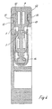
- a bus bar 2 is arranged in the illustrated embodiment, which has at its two ends in each case an insulation-penetrating conductor terminal 3.
- the latter consists of two contact slits 4 between them forming, sharp-edged contact springs 5.
- the conductor to be connected 6 is displaced in a manner to be described in the contact slot 4, wherein the two contact springs 5 penetrate its insulation and contact its wire core.
- Each of the insulation-penetrating conductor terminals 3 is associated with a contact actuating piece 7, which in the illustrated embodiment, in each case in the upper region of the insulating material 1, which is open so far upwards and the narrow outside out, slidably guided.
- the KunststoffierbetHenceists Fantasy 7 is formed like a slide in the illustrated embodiment and is, as indicated by arrows in Figure 1, used in the initial assembly of the Schmalau donener in the Isolierstoffgephase 4.
- ThetechnischbetHenceists fel 7 has a Portereintechnologyö réelle 8, and including in a substantially U-shaped recess in the foot area side driving surfaces 9 and a depth stop 10 for the conductor 6.
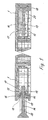
- the contact actuating piece 7 is displaceable after insertion into the insulating material housing 1 between a conductor insertion position (see FIG. 2) and a contacting position (see FIG. 3). These two positions are expediently defined and predetermined by a catch that can be overcome with acceptable force. As can be seen in particular from Figures 1 and 5, this is achieved by a particular embodiment of the foot portion 14 of the contact actuating piece 7 and the cooperating adjacent side wall of the insulating material 1. In the illustrated embodiment, this foot region 14 of the contact actuating piece 7 has laterally projecting stop shoulders 15 in its front region, for which corresponding abutment portions 16 are formed in the narrow-sided outer wall region of the insulating housing 1.
- the stop shoulders 15 are preceded by introduction bevels 17, which in cooperation with introduction bevels 18 of the adjacent side wall portions of the insulating material 1 at the initial installation allow pressing and locking in this illustrated in Figure 5 in the left sub-figure conductor insertion position, after this initial assembly, the contact operation piece 7 then no longer can be removed easily from the insulating material 1.
- a driving through opening 22 In the contact actuating piece 7 is located as a receiving opening for a tool, in particular a screwdriver 21, a driving through opening 22.
- a support Einsteckaussparung 23 In the interior of the insulating 1 in the area below this driving through opening 22 in contact actuating piece 7 is located as a receiving opening for the screwdriver 21 is a support Einsteckaussparung 23, which extends, as shown in particular in FIGS 1-3, extends into the bottom region of the insulating housing 1.
- This support-Einsteckaussparung 23 is located inside the insulating housing, based on the associated insulation-penetrating conductor terminal 3, inside.
- a through hole 24 for the contact pin of a test plug is indicated in phantom in Figure 3. He contacted after insertion an adjacent region of the insulation-penetrating conductor terminal 3. An opposite wall portion of the insulating material 1 forms so far a contact surface 25th
Landscapes
- Connections Arranged To Contact A Plurality Of Conductors (AREA)
- Multi-Conductor Connections (AREA)
- Coupling Device And Connection With Printed Circuit (AREA)
Claims (11)
- Bornes serre-fils avec une connexion de conducteur (3) traversant une isolation,a. avec un boîtier en matériau isolant (1) etb. avec une pièce de manoeuvre de contact (7) présentant des surfaces d'entraînement (9) pour le conducteur (6), coulissant relativement au boîtier en matériau isolant (1) entre une position d'insertion du conducteur et une position de contact,c. des ouvertures de réception pour un outil (21) étant prévues dans la pièce de manoeuvre de contact (7) et dans le boîtier en matériau isolant (1), pour le déplacement de la pièce de manoeuvre de contact (7),d. l'ouverture de réception étant la pièce de manoeuvre de contact (7) pour l'outil, réalisée comme ouverture d'engagement-d'entraînement (22), ete. l'ouverture de réception du boîtier en matériau isolant (1) étant un évidement de logement-d'appui (23) situé sous l'ouverture susmentionnée, et s'étendant jusqu'à la base du boîtier en matériau isolant (1),
caractérisée en ce quef. la pièce de manoeuvre de contact (7) est disposée sur la face supérieure du boîtier en matériau isolant (1) et est entraînable par traction vers la position de contact, et en ce queg. la pièce de manoeuvre de contact est coulissée des deux côtés dans des zones de parois latérales adjacentes du boîtier en matériau isolant (1), ladite pièce de manoeuvre de contact (7) étant logée par des rainures à queue d'aronde (12) dans des glissières en queue d'aronde (11). - Borne serre-fils selon la revendication 1, caractérisée en ce que l'évidement de logement-d'appui (23) est disposé vers l'intérieur du boîtier en matériau isolant (1) par rapport à la connexion correspondante de conducteur (3) traversant une isolation.
- Borne serre-fils selon la revendication 1 ou la revendication 2, caractérisée en ce que l'évidement de logement-d'appui (23) est réalisé en forme de V.
- Borne serre-fils selon la revendication 3, caractérisée en ce que l'évidement de logement-d'appui (23) présente une forme en V à angle aigu.
- Borne serre-fils selon l'une des revendications précédentes, caractérisée en ce que les parties inférieures des glissières en queue d'aronde (11) et les rainures à queue d'aronde (12) correspondantes sont réalisées comme une zone à contre-dépouille (13).
- Borne serre-fils selon l'une des revendications précédentes, caractérisée en ce que la position d'insertion du conducteur de la pièce de manoeuvre de contact (7) ainsi que sa position de contact sont définies par des points d'encliquetage.
- Borne serre-fils selon la revendication 6, caractérisée en ce que, dans la partie d'embase (14) de la pièce de manoeuvre de contact (7) vue dans le sens de coulissement, des butées espacées entre elles sont prévues avec des surfaces obliques (19, 20), pour lesquelles des surfaces opposées complémentaires sont formées dans la zone de paroi latérale extérieure du boîtier en matériau isolant (1).
- Borne serre-fils selon l'une des revendications 6 et 7, caractérisée en ce qu'à l'extrémité antérieure de la partie d'embase (14) de la pièce de manoeuvre de contact (7) sont formés des épaulements de butée (15), pour lesquels des parties en palier (16) sont formées dans la zone de paroi latérale extérieure du boîtier en matériau isolant (1).
- Borne serre-fils selon la revendication 8, caractérisée en ce que des chanfreins d'insertion (17) sont prévus devant les épaulements de butée (15) latéraux.
- Borne serre-fils selon l'une des revendications précédentes, caractérisée en ce qu'un alésage d'engagement (24) pour une prise de test est prévu dans la pièce de manoeuvre de contact (7).
- Borne serre-fils selon la revendication 10, caractérisée en ce qu'une surface d'appui (25) est formée dans le boîtier en matériau isolant (1), vis-à-vis de la zone de mise en contact d'une fiche de test sur la connexion de conducteur (3) traversant une isolation.
Applications Claiming Priority (2)
| Application Number | Priority Date | Filing Date | Title |
|---|---|---|---|
| DE29802674U DE29802674U1 (de) | 1998-02-17 | 1998-02-17 | Reihenklemme mit isolationsdurchdringendem Leiteranschluß |
| DE29802674U | 1998-02-17 |
Publications (2)
| Publication Number | Publication Date |
|---|---|
| EP0936697A1 EP0936697A1 (fr) | 1999-08-18 |
| EP0936697B1 true EP0936697B1 (fr) | 2007-07-04 |
Family
ID=8052760
Family Applications (1)
| Application Number | Title | Priority Date | Filing Date |
|---|---|---|---|
| EP98120772A Expired - Lifetime EP0936697B1 (fr) | 1998-02-17 | 1998-11-02 | Reglette avec bornes à déplacement d'isolant |
Country Status (5)
| Country | Link |
|---|---|
| US (1) | US6120315A (fr) |
| EP (1) | EP0936697B1 (fr) |
| CN (1) | CN1106053C (fr) |
| AT (1) | ATE366466T1 (fr) |
| DE (2) | DE29802674U1 (fr) |
Families Citing this family (41)
| Publication number | Priority date | Publication date | Assignee | Title |
|---|---|---|---|---|
| DE19711128C1 (de) * | 1997-03-10 | 1998-07-30 | Krone Ag | Verteilerleiste für die Telekommunikations- und Datentechnik |
| FR2782196B1 (fr) * | 1998-08-10 | 2002-02-15 | Entrelec Sa | Dispositif de connexion a fente denudante pour fil electrique |
| DE19921769A1 (de) | 1999-05-11 | 2000-11-16 | Siemens Ag | Schneidklemmkontakt und Verbindungsklemme |
| DE19921960C1 (de) * | 1999-05-14 | 2001-05-17 | Wieland Electric Gmbh | Schraubenlose Anschlußklemme |
| AU4563500A (en) | 1999-05-14 | 2000-12-05 | Wieland Electric Gmbh | Screwless terminal |
| DE29918557U1 (de) * | 1999-10-21 | 2001-02-22 | Weidmüller Interface GmbH & Co, 32760 Detmold | Reihenklemme mit isolationsdurchdringendem Schneidanschluß |
| EP1120859A3 (fr) * | 2000-01-27 | 2002-06-12 | Weidmüller Interface GmbH & Co. | Barrette à borne avec dispositif de connexion autodénudant |
| DE10006143A1 (de) * | 2000-02-11 | 2001-08-16 | Prec Controls Bt Veszprem | Gerätesteckdose |
| US6500020B2 (en) * | 2000-06-20 | 2002-12-31 | Corning Cable Systems Llc | Top loading customer bridge |
| DE10036718B4 (de) | 2000-07-27 | 2004-10-21 | Siemens Ag | Schneidklemmeinrichtung |
| DE10039961C1 (de) * | 2000-08-16 | 2002-02-28 | Siemens Ag | Elektrisches Gerät |
| ATE331317T1 (de) * | 2000-09-25 | 2006-07-15 | Weidmueller Interface | Reihenklemme mit schneidkontakten und kontaktbetätigungsstücken |
| DE20106523U1 (de) * | 2000-09-25 | 2002-02-14 | Weidmüller Interface GmbH & Co., 32760 Detmold | Reihenklemme mit Schneidkontakten und Anschlußvorrichtung |
| DE20106525U1 (de) * | 2000-09-25 | 2002-02-14 | Weidmüller Interface GmbH & Co., 32760 Detmold | Reihenklemme mit Schneidkontakten und Kontaktbetätigungsstücken |
| ES2231360T3 (es) | 2000-09-25 | 2005-05-16 | WEIDMULLER INTERFACE GMBH & CO. | Borne de terminal con contactos de corte y dispositivo de conexion. |
| DE20020450U1 (de) * | 2000-11-30 | 2002-04-11 | Weidmüller Interface GmbH & Co., 32760 Detmold | Reihenklemme mit Einrichtung zum Ausnehmen von Leiterresten |
| DE20105806U1 (de) * | 2001-04-03 | 2002-08-22 | Weidmüller Interface GmbH & Co., 32760 Detmold | Reihenklemme mit Schneidkontakten und Kontaktbetätigungsstücken |
| DE20106710U1 (de) * | 2001-04-18 | 2001-08-09 | Phoenix Contact Gmbh & Co., 32825 Blomberg | Elektrische Klemme |
| DE20110839U1 (de) * | 2001-06-30 | 2002-11-07 | Weidmüller Interface GmbH & Co., 32760 Detmold | Reihenklemme und Führungshülse |
| EP1286421B1 (fr) * | 2001-08-20 | 2007-12-05 | Woertz Ag | Borne électrique |
| DE20114612U1 (de) * | 2001-09-05 | 2003-01-16 | Weidmüller Interface GmbH & Co., 32760 Detmold | Reihenklemme mit Schneidkontakten und Anschlußvorrichtung |
| DE20118666U1 (de) * | 2001-11-15 | 2003-03-27 | Weidmüller Interface GmbH & Co., 32760 Detmold | Reihenklemme und Führungshülse |
| US6692291B2 (en) * | 2002-05-02 | 2004-02-17 | Ching-Hsiung Chen | Cable piercing device for use with a plug |
| DE20214875U1 (de) * | 2002-09-26 | 2004-02-19 | Weidmüller Interface Gmbh & Co. | Reihenklemmenanordnung mit Reihenklemme und Anschlußstecker |
| DE20309334U1 (de) * | 2003-06-17 | 2004-11-11 | Weidmüller Interface GmbH & Co. KG | Anschlußklemme |
| US6872089B1 (en) * | 2003-11-03 | 2005-03-29 | Ching-Hsiung Chen | Puncturing type cable coupling apparatus |
| DE202004013363U1 (de) | 2004-04-28 | 2005-09-08 | Weidmüller Interface GmbH & Co. KG | Anschlußvorrichtung mit Betätigungsvorrichtung |
| CN100385747C (zh) * | 2004-04-28 | 2008-04-30 | 威德米勒界面有限公司及两合公司 | 带有操纵装置的连接装置 |
| DE102005003199A1 (de) * | 2004-08-24 | 2006-03-02 | Weidmüller Interface GmbH & Co. KG | Montage- und Anschluß-System für elektrische Geräte |
| FR2874750B1 (fr) * | 2004-08-30 | 2016-11-04 | Mft D'appareillage Electrique De Cahors Maec | Module de connexion pour raccorder deux premiers conducteurs isoles relies au reseau telephonique a deux seconds conducteurs isoles destines a etre relies a un appareil telephonique d'un abonne |
| DE202005012792U1 (de) * | 2005-08-11 | 2006-02-16 | Phoenix Contact Gmbh & Co. Kg | Elektrische Klemme |
| DE102005040657A1 (de) * | 2005-08-26 | 2007-03-15 | Phoenix Contact Gmbh & Co. Kg | Elektrische Anschlussklemme |
| DE202005014719U1 (de) * | 2005-09-17 | 2007-02-01 | Weidmüller Interface GmbH & Co. KG | Anschluß-System zur Realisierung von Abzweigungen an durchgehenden Leitern |
| DE202006012799U1 (de) | 2006-02-03 | 2007-06-14 | Weidmüller Interface GmbH & Co. KG | Anschlussleiste für elektrische Geräte, insbesondere für Stecker |
| FR2918805B1 (fr) * | 2007-07-09 | 2009-09-25 | Amphenol Air Lb Soc Par Action | Borne de raccordement electrique autodenudante. |
| ES1067865Y (es) * | 2008-05-07 | 2008-10-01 | Simon Sa | Enclavamiento para tecla de embornado rapido en mecanismos electricos |
| DE202008015307U1 (de) * | 2008-11-19 | 2010-04-08 | Weidmüller Interface GmbH & Co. KG | Anschluss-System zur Realisierung von Abzweigungen an durchgehenden Leitern |
| JP2013020855A (ja) * | 2011-07-12 | 2013-01-31 | Sanyo Electric Co Ltd | 電源装置及び電源装置を備える車両 |
| US9184515B1 (en) * | 2012-09-28 | 2015-11-10 | Anthony Freakes | Terminal blocks for printed circuit boards |
| DE102015100823B4 (de) * | 2015-01-21 | 2021-12-09 | Phoenix Contact Gmbh & Co. Kg | Elektrische Anschlussklemme |
| DE102018109489A1 (de) * | 2018-04-20 | 2019-10-24 | Phoenix Contact Gmbh & Co. Kg | Automatisierungsfähige Anschlussklemme und Verfahren zum Kontaktieren eines Leiters |
Family Cites Families (12)
| Publication number | Priority date | Publication date | Assignee | Title |
|---|---|---|---|---|
| DE2902536C2 (de) * | 1979-01-24 | 1980-12-18 | C. A. Weidmueller Kg, 4930 Detmold | Reihenklemme |
| FR2503464A1 (fr) * | 1981-04-03 | 1982-10-08 | Alsthom Cgee | Bloc de jonction a raccordement electrique sans denudage |
| FR2516711A1 (fr) * | 1981-11-17 | 1983-05-20 | Alsthom Cgee | Borne de raccordement de fil electrique sans denudage |
| FR2598038B1 (fr) * | 1986-04-28 | 1990-09-21 | Alsthom Cgee | Agencement de connexion a fente denudante pour fil electrique |
| GB2196492B (en) * | 1986-10-02 | 1990-11-14 | Amp Inc | An electrical connector and an electrical terminal |
| US4781618A (en) * | 1987-06-25 | 1988-11-01 | Reed Devices, Inc. | Pushbutton electrical terminal |
| US5295857A (en) * | 1992-12-23 | 1994-03-22 | Toly Elde V | Electrical connector with improved wire termination system |
| US5423694A (en) * | 1993-04-12 | 1995-06-13 | Raychem Corporation | Telecommunications terminal block |
| FR2718295B1 (fr) * | 1994-03-30 | 1996-04-26 | Alcatel Cable Interface | Poussoir de raccordement et réglette de connexion équipée de tels poussoirs. |
| FR2722033B1 (fr) * | 1994-07-04 | 1996-08-02 | Entrelec Sa | Module de raccordement electrique a piece de connexion du type a fente de retenue de fil dotee d'une embouchure denudante |
| DE4437022C1 (de) * | 1994-10-08 | 1996-02-22 | Krone Ag | Anschlußelement |
| DE19603960B4 (de) * | 1996-01-26 | 2008-03-06 | Wago Verwaltungsgesellschaft Mbh | Mehrpoliger Abzweig-Steckverbinder |
-
1998
- 1998-02-17 DE DE29802674U patent/DE29802674U1/de not_active Expired - Lifetime
- 1998-11-02 EP EP98120772A patent/EP0936697B1/fr not_active Expired - Lifetime
- 1998-11-02 AT AT98120772T patent/ATE366466T1/de not_active IP Right Cessation
- 1998-11-02 DE DE59814051T patent/DE59814051D1/de not_active Expired - Lifetime
- 1998-12-25 CN CN98125494A patent/CN1106053C/zh not_active Expired - Fee Related
-
1999
- 1999-02-05 US US09/245,411 patent/US6120315A/en not_active Expired - Fee Related
Non-Patent Citations (1)
| Title |
|---|
| None * |
Also Published As
| Publication number | Publication date |
|---|---|
| ATE366466T1 (de) | 2007-07-15 |
| US6120315A (en) | 2000-09-19 |
| CN1231528A (zh) | 1999-10-13 |
| CN1106053C (zh) | 2003-04-16 |
| DE59814051D1 (de) | 2007-08-16 |
| DE29802674U1 (de) | 1998-04-16 |
| EP0936697A1 (fr) | 1999-08-18 |
Similar Documents
| Publication | Publication Date | Title |
|---|---|---|
| EP0936697B1 (fr) | Reglette avec bornes à déplacement d'isolant | |
| EP3298659B1 (fr) | Borne de connexion de conducteur | |
| EP1956684B1 (fr) | Contact universel | |
| EP0899818B1 (fr) | Borne de connexion électrique, notamment pour utilisation sur des plaques de circuits imprimés | |
| EP2862236B1 (fr) | Borne de connexion électrique | |
| EP4342031B1 (fr) | Borne de connexion de conducteur comprenant au moins un raccord de borne à serrage par ressort | |
| DE202017103185U1 (de) | Federkraftklemme für Leiter | |
| DE102016115601A1 (de) | Federkraftklemmanschluss | |
| WO2016046372A1 (fr) | Borne de raccordement de conducteur et procédé de montage de ladite borne | |
| DE102017109694B4 (de) | Anschlussklemme | |
| EP3454422A1 (fr) | Borne de connexion conductrice | |
| WO2023213511A1 (fr) | Dispositif de connexion conçu sous la forme d'une borne à ressort pour connecter un conducteur | |
| DE10103187B4 (de) | Elektrische Klemme | |
| EP4342030B1 (fr) | Borne de connexion de conducteur comprenant au moins une connexion par borne à ressort | |
| EP1191633A2 (fr) | Barette à borne à déplacement d'isolation avec pièces pour contacter les fils avec les bornes | |
| EP1523065B1 (fr) | Borne électrique | |
| DE2706988C2 (de) | Schraubenlose Anschlußklemme zur Stromübertragung von elektrischen Leitern | |
| DE102008014180B4 (de) | Trennklemme, insbesondere Neutralleiter-Trennklemme | |
| WO2000070714A1 (fr) | Borne de raccordement sans vis | |
| DE102007029047A1 (de) | Anschlußvorrichtung für ein Flachkabel und Betätigungswerkzeug zur Verwendung bei einer Anschlußvorrichtung | |
| EP3855572A1 (fr) | Borne de liaison | |
| EP1463150A2 (fr) | Appareil électrique, en particulier barette à bornes avec contacts autodénudants | |
| EP4123839A1 (fr) | Borne de connexion électrique pourvue de levier de libération | |
| DE202023105328U1 (de) | Federkraftklemmanschluss und Leiteranschlussklemme | |
| DE20106523U1 (de) | Reihenklemme mit Schneidkontakten und Anschlußvorrichtung |
Legal Events
| Date | Code | Title | Description |
|---|---|---|---|
| PUAI | Public reference made under article 153(3) epc to a published international application that has entered the european phase |
Free format text: ORIGINAL CODE: 0009012 |
|
| AK | Designated contracting states |
Kind code of ref document: A1 Designated state(s): AT CH DE ES FR GB IT LI NL SE |
|
| AX | Request for extension of the european patent |
Free format text: AL;LT;LV;MK;RO;SI |
|
| 17P | Request for examination filed |
Effective date: 19991019 |
|
| AKX | Designation fees paid |
Free format text: AT CH DE ES FR GB IT LI NL SE |
|
| GRAP | Despatch of communication of intention to grant a patent |
Free format text: ORIGINAL CODE: EPIDOSNIGR1 |
|
| GRAS | Grant fee paid |
Free format text: ORIGINAL CODE: EPIDOSNIGR3 |
|
| GRAA | (expected) grant |
Free format text: ORIGINAL CODE: 0009210 |
|
| AK | Designated contracting states |
Kind code of ref document: B1 Designated state(s): AT CH DE ES FR GB IT LI NL SE |
|
| REG | Reference to a national code |
Ref country code: GB Ref legal event code: FG4D Free format text: NOT ENGLISH |
|
| REG | Reference to a national code |
Ref country code: CH Ref legal event code: EP |
|
| REF | Corresponds to: |
Ref document number: 59814051 Country of ref document: DE Date of ref document: 20070816 Kind code of ref document: P |
|
| NLV1 | Nl: lapsed or annulled due to failure to fulfill the requirements of art. 29p and 29m of the patents act | ||
| GBV | Gb: ep patent (uk) treated as always having been void in accordance with gb section 77(7)/1977 [no translation filed] |
Effective date: 20070704 |
|
| PG25 | Lapsed in a contracting state [announced via postgrant information from national office to epo] |
Ref country code: NL Free format text: LAPSE BECAUSE OF FAILURE TO SUBMIT A TRANSLATION OF THE DESCRIPTION OR TO PAY THE FEE WITHIN THE PRESCRIBED TIME-LIMIT Effective date: 20070704 Ref country code: ES Free format text: LAPSE BECAUSE OF FAILURE TO SUBMIT A TRANSLATION OF THE DESCRIPTION OR TO PAY THE FEE WITHIN THE PRESCRIBED TIME-LIMIT Effective date: 20071015 |
|
| EN | Fr: translation not filed | ||
| PLBE | No opposition filed within time limit |
Free format text: ORIGINAL CODE: 0009261 |
|
| STAA | Information on the status of an ep patent application or granted ep patent |
Free format text: STATUS: NO OPPOSITION FILED WITHIN TIME LIMIT |
|
| PG25 | Lapsed in a contracting state [announced via postgrant information from national office to epo] |
Ref country code: GB Free format text: LAPSE BECAUSE OF FAILURE TO SUBMIT A TRANSLATION OF THE DESCRIPTION OR TO PAY THE FEE WITHIN THE PRESCRIBED TIME-LIMIT Effective date: 20070704 |
|
| 26N | No opposition filed |
Effective date: 20080407 |
|
| PG25 | Lapsed in a contracting state [announced via postgrant information from national office to epo] |
Ref country code: SE Free format text: LAPSE BECAUSE OF FAILURE TO SUBMIT A TRANSLATION OF THE DESCRIPTION OR TO PAY THE FEE WITHIN THE PRESCRIBED TIME-LIMIT Effective date: 20071004 |
|
| PG25 | Lapsed in a contracting state [announced via postgrant information from national office to epo] |
Ref country code: FR Free format text: LAPSE BECAUSE OF FAILURE TO SUBMIT A TRANSLATION OF THE DESCRIPTION OR TO PAY THE FEE WITHIN THE PRESCRIBED TIME-LIMIT Effective date: 20080229 Ref country code: CH Free format text: LAPSE BECAUSE OF NON-PAYMENT OF DUE FEES Effective date: 20071130 Ref country code: LI Free format text: LAPSE BECAUSE OF NON-PAYMENT OF DUE FEES Effective date: 20071130 |
|
| REG | Reference to a national code |
Ref country code: CH Ref legal event code: PL |
|
| PG25 | Lapsed in a contracting state [announced via postgrant information from national office to epo] |
Ref country code: AT Free format text: LAPSE BECAUSE OF NON-PAYMENT OF DUE FEES Effective date: 20071102 |
|
| PG25 | Lapsed in a contracting state [announced via postgrant information from national office to epo] |
Ref country code: IT Free format text: LAPSE BECAUSE OF NON-PAYMENT OF DUE FEES Effective date: 20071130 |
|
| PGFP | Annual fee paid to national office [announced via postgrant information from national office to epo] |
Ref country code: DE Payment date: 20131121 Year of fee payment: 16 |
|
| REG | Reference to a national code |
Ref country code: DE Ref legal event code: R119 Ref document number: 59814051 Country of ref document: DE |
|
| PG25 | Lapsed in a contracting state [announced via postgrant information from national office to epo] |
Ref country code: DE Free format text: LAPSE BECAUSE OF NON-PAYMENT OF DUE FEES Effective date: 20150602 |