EP0936779A1 - Système de réseau - Google Patents
Système de réseau Download PDFInfo
- Publication number
- EP0936779A1 EP0936779A1 EP99101071A EP99101071A EP0936779A1 EP 0936779 A1 EP0936779 A1 EP 0936779A1 EP 99101071 A EP99101071 A EP 99101071A EP 99101071 A EP99101071 A EP 99101071A EP 0936779 A1 EP0936779 A1 EP 0936779A1
- Authority
- EP
- European Patent Office
- Prior art keywords
- node
- loop
- token
- nodes
- packet
- Prior art date
- Legal status (The legal status is an assumption and is not a legal conclusion. Google has not performed a legal analysis and makes no representation as to the accuracy of the status listed.)
- Granted
Links
Images


Classifications
-
- H—ELECTRICITY
- H04—ELECTRIC COMMUNICATION TECHNIQUE
- H04L—TRANSMISSION OF DIGITAL INFORMATION, e.g. TELEGRAPHIC COMMUNICATION
- H04L12/00—Data switching networks
- H04L12/28—Data switching networks characterised by path configuration, e.g. LAN [Local Area Networks] or WAN [Wide Area Networks]
- H04L12/44—Star or tree networks
-
- H—ELECTRICITY
- H04—ELECTRIC COMMUNICATION TECHNIQUE
- H04L—TRANSMISSION OF DIGITAL INFORMATION, e.g. TELEGRAPHIC COMMUNICATION
- H04L12/00—Data switching networks
- H04L12/28—Data switching networks characterised by path configuration, e.g. LAN [Local Area Networks] or WAN [Wide Area Networks]
-
- H—ELECTRICITY
- H04—ELECTRIC COMMUNICATION TECHNIQUE
- H04L—TRANSMISSION OF DIGITAL INFORMATION, e.g. TELEGRAPHIC COMMUNICATION
- H04L12/00—Data switching networks
- H04L12/28—Data switching networks characterised by path configuration, e.g. LAN [Local Area Networks] or WAN [Wide Area Networks]
- H04L12/46—Interconnection of networks
- H04L12/4637—Interconnected ring systems
Definitions
- the present invention relates to a network system which realizes connection of a bus type network and a loop type network.
- reference numeral 101 designates a bus type network
- 101a designates nodes connected to the bus type network 101
- 102 designates a gateway or a router
- 103 designates a loop type network
- 103a designates nodes connected to the loop type network 103.
- the bus type network 101 and the loop type network 103 are interconnected via the gateway or the router 102.
- the loop type network comprises less optical fibers for connecting nodes and less optical modules, and therefore provides cost-effectiveness and high node extensibility.
- the loop type network is less reliable and requires much maintenance.
- the bus type network comprises more optical fibers or optical modules and thereby is not cost-effective, the breakage of parts of the optical fibers or the failures of the nodes causes the nodes to be in inoperable state but does not affect the whole network, and therefore it is reliable and requires little maintenance.
- a network system in which at least one loop comprising plural loop-connected nodes and at least one loop comprising either a single node or plural loop-connected nodes are directly connected to a common transmission line, wherein a signal output from one of the nodes is transmitted to all the nodes, and then is discarded by one of the nodes in each loop. Therefore, without the use of computers or complicated control devices, it is possible to realize connection of a loop type network and a bus type network in which a single node and a group of loop-connected nodes are connected to a physically common medium.
- a network system in which at least one loop comprising plural loop-connected nodes and at least one loop comprising either a single node or plural loop-connected nodes are bus-connected by the use of an optical star coupler, the nodes of the loop each has a unique node identifier, one node included in one of plural loops serves as a token master node, and nodes other than the node serving as the token master node serve as slave nodes, wherein the token master node includes: a token transmitting apparatus for transmitting a token packet which contains a transmission node identifier as a node identifier of a node which is allowed to transmit a data packet and a receiving node identifier as a node identifier of a node which is allowed to receive the transmitted data packet; a token analyzing apparatus for analyzing the token packet; a storage for temporarily storing connection information indicating whether an output of the self node is directly connected to the bus or connected to another node included in the corresponding
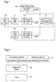
- Figure 1 shows an example of construction of a network system according to the first embodiment of the present invention.
- reference numerals 100, 110, 111, 112, 120, and 121 designate nodes connected to a network
- reference numeral 15 designates an optical star coupler.
- the node 100 is a token master node and the nodes 110, 111, 112, 120, and 121 are slave nodes.
- the node 100 is a loop master of a loop 0 comprising the node 100.
- the node 110 is a loop master of a loop 1 comprising the nodes 110, 111, and 112.
- the node 120 is a loop master of a loop 2 comprising the nodes 120 and 121.
- arrows show flow of data.
- the loops (loop1, loop2) in which plural nodes are connected in one direction or the loop (loop 0) comprising a single loop are connected to the optical star coupler 15, and among the nodes of respective loops, the nodes having outputs connected to the optical star coupler 15 serve the loop masters.
- Figure 2 shows a structure of a packet transmitted over the network in the network system according to the first embodiment of the present invention.
- reference numerals 21, 22, and 23 designate a token packet, a DS (Destination Status) packet, and a data packet, respectively.
- the token packet 21, as shown in figure 2, includes a transmission node identifier (ID) and a receiving node identifier (ID).
- the transmission node ID is a node ID of a node which is allowed to transmit data by the token master node
- the receiving node ID is a node ID of a node which is allowed to receive data by the token master node.
- the node IDs each comprises a loop address to which the corresponding node belongs and a node address on the loop.
- the loop address is a number unique to each loop
- the node address is a number unique to each node.
- To specify a node on the network specify a loop address of a loop to which the node belongs and a node address of the node on the loop.
- the node ID is described as (loop address, node address). For instance, the node ID of a node comprising a loop address 1 and a node address 2 is expressed as (1, 2).
- a DS packet 22, as shown in figure 2, includes a field of "Destination Status".
- the DS packet 22 contains information indicating whether or not the receiving node can receive data.
- a data packet 23 includes a field of data to be transmitted.
- Figure 3 shows packets transmitted over the network.
- reference numerals 31, 32, and 33 designate the token packet, the DS packet, and the data packet, respectively.
- the token packet, the DS packet, and the data packet are transmitted through the network in this order, and this is repeatedly performed at regular time intervals.
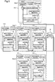
- FIG 4 shows a detailed construction of the network system of the first embodiment.
- reference numerals 100, 110, 111, 112, 120, and 121 designate nodes connected to the network
- reference numeral 15 designates an optical star coupler.
- the node 100 is a token master node
- the nodes 110, 111, 112, 120, and 121 are slave nodes.
- the node 100 belongs to the loop 0, the nodes 110, 111, and 112 belong to the loop 1, and the nodes 120 and 121 belong to the loop 2.
- the nodes 100, 110, and 120 are loop masters.
- the node IDs of the node 100, the node 110, the node 111, the node 112, the node 120, and the node 121 are (0. 0), (1. 0), (1. 1), (1. 2), (2. 0) and (2. 1), respectively. That is, each node has a node ID unique to it.
- the slave nodes 111, 112, and 121 and the loop master nodes 110 and 120 each comprises a token analyzing apparatus which analyzes a token and a packet, a nonvolatile memory which stores initialization, a storage connected to the token analyzing apparatus and the nonvolatile memory, a data transmitting apparatus for transmitting data, and a switch for connecting or breaking the loop. Placing the switch to A connects the loop and placing the switch to B breaks the loop.
- the token master node 100 includes a token transmitting apparatus for transmitting token in addition to the components of the slave node. Placing the switch to A connects the loop and placing the switch to B breaks the loop.
- the nonvolatile memory anything will do so long as it can store initialization and set the initialization in the storage.
- the memory may be implemented by a DIP switch and the like.
- the token master node 100 transmits a token packet of a transmission node ID (2, 1) and a receiving node ID (1, 1).
- the node which has transmitted packets performs switching so as to discard the packets sent back to itself.
- the loop master performs switching, thereby discarding packets transmitted from the node which belongs to another loop and passing packets transmitted from the node which belongs to the corresponding loop.
- the operation sequence is an initialization sequence and a normal operation sequence.
- the initialization sequence is activated when power is applied or resetting is performed.
- information preset in the nonvolatile memory or the DIP switch and the like is read into the storage.
- the token master node operates as the token master node and the loop masters operates as the loop masters.
- the loop masters each knows the loop address ("0") of the loop to which the token mater node belongs, and every node including the token master node knows the node ID (loop addresses and node addresses) of itself.
- FIG 9 shows an example of information preset in the volatile memory. Assume that addresses on the nonvolatile memory of each flag, each address, and each node ID are known in this illustrated example.
- information stored in the address of the token master node flag on the nonvolatile memory is read, and when it is "0", “other than token master” is set, while it is "1", “token master” is set. The same goes for the loop master flag, the loop address of the token master node, and the node ID.
- the normal operation sequence is an operation sequence in which the node transmits and receives packets, and includes a token mode of transmitting the token packet, a DS mode of transmitting the DS packet, and a data mode of transmitting the data packet.
- a token mode of transmitting the token packet a token mode of transmitting the token packet
- a DS mode of transmitting the DS packet a data mode of transmitting the data packet.
- Figure 4 shows states of switches of respective nodes when the token packet is transmitted and flow of the token packet.
- bold lines show flow of packets.
- the token transmitting apparatus constructs the token packet, the data transmitting apparatus restructures the packet to take a form to be transmitted over the network, and then the token analyzing apparatus places the switch to the B so as to transmit the token packet.
- the transmission node ID and the receiving node ID specified by the token packet is (2. 1) and (1. 1), respectively.
- the token analyzing apparatus of each of the loop masters 110 and 120 compares the loop address "0" of the token master node 100 stored in the initialization sequence to the address of the corresponding loop ("1" - the loop master 110 "2" - the loop master 120). Since there is no match between them, the token analyzing apparatus decides that the packet has been sent from another loop and then places the switch to B.
- the token analyzing apparatus of each of the slave nodes 111, 112, and 121 places the switch to A, thereby passing the packet in the token mode.
- the token packet transmitted from the token master node 100 is sent through the optical star coupler 15 to the nodes 100, 112, and 121.
- the token packet transmitted from the optical star coupler 15 is discarded by the token analyzing apparatus of the token master node 100.
- the token packet is transmitted to the slave node 112, the slave node 111, and the loop master 110 in this order, and is discarded by the token analyzing apparatus of the loop master 110.
- the token packet is transmitted to the slave node 121 and the loop master 120 in this order, and is discarded by the token analyzing apparatus of the loop master 120.
- the token analyzing apparatus of each of the nodes stores the transmission ID and the receiving ID contained in the received token packet in the storage.
- the token packet is transmitted in the token mode from the token master node 100 to all the nodes and received by them, and then discarded by the loop master and the token master node.
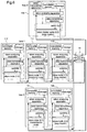
- Figure 5 shows states of switches of respective nodes when the DS packet is transmitted, and flow of the DS packet.
- the bold line shows flow of the DS packet.
- the token analyzing apparatus of each of the nodes including the token master node and the loop masters makes comparison between the receiving node ID stored in the storage resulting from operation in the token mode and the node ID of the corresponding node, and when there is a match between them (the node 111 in this case), and the corresponding node is in the state where it can receive data, it constructs a DS packet indicating "data receivable".
- the token analyzing apparatus constructs the DS packet indicating "data unreceivable" and the data transmitting apparatus restructures the DS packet to take a form to be transmitted over the network, followed by placing a switch to B so as to transmit the DS packet.
- the token analyzing apparatus of the loop master 110 since there is no match between the receiving node ID stored in the storage and the node ID of the corresponding node, decides that the node will not output the DS packet. Then, the token analyzing apparatus compares the loop address "1" of the receiving ID stored in the storage and the address "1" of the corresponding loop, and since there is a match between them, it decides that the node in the loop will output the DS packet, and then places the switch to A.
- the token analyzing apparatus of each of the loop masters 100 and 120 since there is no match between the receiving node ID stored in the storage and the node ID of the corresponding node, decides that the node will not output the DS packet. Then, the token analyzing apparatus compares the loop address "1" of the receiving node ID to the address of the corresponding loop ("0" -the node 100, "2" -the node 120), and since there is no match between them, it decides that the Ds packet will be transmitted from the node in another loop, and then places the switch to B.
- the token analyzing apparatus of each of the slave nodes 112 and 121 since there is no match between the receiving node ID stored in the storage and the node ID of the corresponding node, it places the switch to A.
- the DS packet transmitted from the node 111 passes through the node 110, and the optical star coupler 15, to the nodes 100, 112, and 121.
- the DS packet transmitted from the optical star coupler 15 is discarded by the token master node 100.
- the DS packet is transmitted to the slave node 112 and the slave node 111 in this order, and is discarded by the node 111.
- the Ds packet is transmitted to the slave node 121 and the loop master 120 in this order, and is discarded by the loop master 120.
- the token analyzing apparatus of each of all the nodes including the token master node makes comparison between the transmission node ID stored in the storage resulting from operation in the token master node and the node ID of the corresponding node, and when there is a match between them (the node 121 in this case), receives the transmitted DS packet and stores its content in the storage.
- the DS packet is thus transmitted from the node 111 specified as the receiving node by the token packet to all the nodes, received by the node 121 specified as the transmission node by the token packet, and then discarded by the loop masters 100 and 120 and the node 111 which has transmitted the DS packet.
- Figure 6 shows states of switches of respective nodes when the data packet is transmitted and flow of the data packet.
- bold lines show flow of the data packet.
- the token analyzing apparatus of each of the nodes including the token master node and the loop master makes comparison between the transmission node ID stored in the storage resulting from operation in the token mode and the node ID of the corresponding node, and when there is a match between them (the node 121 in this case), and the content of the DS packet stored in the DS mode indicates "data receivable", it constructs a data packet, the data transmitting apparatus restructures data to take a form to be transmitted over the network, and the token analyzing apparatus places the switch to B, thereby transmitting the data packet.
- the token analyzing apparatus will not transmit the data packet, if there is a match between the transmission node ID stored in the storage and the node ID of the corresponding node but the content of the DS packet stored in the DS mode indicates "data unreceivable".
- the token analyzing apparatus of the loop master 120 since there is no match between the transmission node ID stored in the storage and the node ID of the corresponding node, decides that the node will not output the data packet. Then, the token analyzing apparatus makes comparison between the loop address "2" of the transmission node ID and the loop address "2" of the corresponding loop, and since there is a match between them, it decides that the node in the corresponding loop will transmit the data packet and then places the switch to A.
- the token analyzing apparatus of each of the loop masters 100 and 110 since there is no match between the transmission node ID stored in the storage and the node ID of the corresponding node, decides that the node will not transmit the data packet. Then, the token analyzing apparatus makes comparison between the loop address "2" of the transmission node ID stored in the storage and the loop address ("0"-100, "1"-110) of the corresponding loop, and since there is no match between them, it decides that the node in another loop will transmit the data packet, and then places the switch to B.
- the token analyzing apparatus of each of the slave nodes 112 and 111 since there is no match between the transmission ID stored in the storage and the node ID of the corresponding node, places the switch to A so as to pass the packet.
- the data packet transmitted from the node 121 passes through the node 120 and the optical star coupler 15 to the nodes 100, 112, and 121.
- the data packet transmitted from the optical star coupler 15 is discarded by the token analyzing apparatus of the token master node 100.
- the data packet is transmitted to the slave node 112, the slave node 111, and the loop master 110 in this order, and is discarded by the token analyzing apparatus of the loop master 110.
- the data packet transmitted from the optical star coupler 15 is discarded by the slave node 121 which has transmitted the data packet.
- the token analyzing apparatus of each of all the nodes including the token master node makes comparison between the receiving node ID stored in the storage and the node ID of the corresponding node, and when there is a match between them, it receives the transmitted data packet.
- the data packet is thus transmitted from the node 121 specified as the transmission node by the token packet to all the nodes, received by the node 111 specified as the receiving node by the token packet, and discarded by the loop masters 100 and 110 and the node 121 which has transmitted the data packet.
- the token mode is reentered, and data transmission is repeated in the same sequence: the token mode, the DS mode, the data mode....
- the node which has transmitted the packet (the token packet, the DS packet, and the data packet), performs switching so that the packet sent back to itself will be discarded, and the loop master perform switching so that the packet sent from the node belonging to another loop will be discarded, whereby the packets are transmitted or discarded.
- MAC Media Access Control
- the means for performing switching so that packet received by each node is transmitted to its upper node or discarded by itself is implemented by a physical switch which shortens or breaks input and output terminals of the nodes, anything will do so long as it can perform such switching.
- the construction of the network system is not limited to that shown in the first embodiment. It is possible to arbitrary set the number of the loops, the number of nodes in the loops, and the number of the nodes directly connected to the optical star coupler, within bit widths of the node IDs or physically limited ranges.
- the token master node is directly connected to the optical star coupler, it is possible to dispose the token master node in an arbitrary position of the loop.
- the token packet, the DS packet, and the data packet are transmitted in this order, while in a network system where the data is discarded on the transmission line and retransmission of the data is requested and allowed to and by a transmission source, or after the corresponding receiving node has overwritten data, and retransmission of the lost data group is requested and allowed to and by the transmission source, if the receiving node cannot receive data, the phase of transmitting the DS packet may be omitted.
- node 100 While in the network system of the first embodiment, provided is one node (node 100) on the network system which includes the token transmitting apparatus and serves as the token master node, plural candidate nodes which might serve as the token master node may be provided on the network system. It should be remembered that one of the plural candidate nodes is set to serve as the token master node by information preset in the nonvolatile memory or the DIP switch and the like.
- reference numerals 71 and 72 designate nodes, respectively.
- a bus 75 comprising an optical star coupler and a signal output apparatus 75a is provided with a signal line 74 for outputting signals to the node 72 connected to the signal output apparatus 75a and the optical star coupler
- the nodes 71 and 72 on the loop type network include signal detecting apparatuses 71a and 72a for detecting signals on the signal line 74, respectively, and the signal output apparatus 75a sends a signal indicating direct connection to the optical star coupler, which the signal detecting apparatus 72a of the node 72 directly connected to the optical star coupler detects and performs setting in the storage so that the node 72 operates as the loop master.
- the node 72 directly connected to the optical star coupler automatically recognizes that it will serve as the loop master.
- a node 81 may be connected to a setting apparatus 82, which performs setting in a storage 81a.
- the setting apparatus 82 may be implemented by a computer and the like, and the node 81 may be connected to the setting apparatus 82 by serial communication.
- application of the system for providing the loop addresses unique to the loops to which the nodes belong and transmitting or discarding data by the use of the loop masters according to the present invention is not limited to the network system by the use of the token described above.
- this may be applied to a network system which employs a CSMA (Carrier Sense Multiple Access) system, a TDMA (Time-Division Multiple Access) system, or an arbitration system using a bus arbiter.
- CSMA Carrier Sense Multiple Access
- TDMA Time-Division Multiple Access
- loop addresses unique to loops to which the nodes belong transmission source loop addresses are added to transmission data, the loop master analyzes the loop addresses to transmit or discard data, and the transmission node discards the data sent back to itself, thereby realizing connection of the bus and the loop by the use of the optical star coupler, as in the case of the above embodiment.
Landscapes
- Engineering & Computer Science (AREA)
- Computer Networks & Wireless Communication (AREA)
- Signal Processing (AREA)
- Small-Scale Networks (AREA)
- Optical Communication System (AREA)
Applications Claiming Priority (4)
| Application Number | Priority Date | Filing Date | Title |
|---|---|---|---|
| JP3096198 | 1998-02-13 | ||
| JP3096198 | 1998-02-13 | ||
| JP11345998 | 1998-04-23 | ||
| JP10113459A JP2955555B1 (ja) | 1998-02-13 | 1998-04-23 | ネットワークシステム |
Publications (2)
| Publication Number | Publication Date |
|---|---|
| EP0936779A1 true EP0936779A1 (fr) | 1999-08-18 |
| EP0936779B1 EP0936779B1 (fr) | 2006-05-31 |
Family
ID=26369405
Family Applications (1)
| Application Number | Title | Priority Date | Filing Date |
|---|---|---|---|
| EP99101071A Expired - Lifetime EP0936779B1 (fr) | 1998-02-13 | 1999-01-25 | Système de réseau |
Country Status (9)
| Country | Link |
|---|---|
| US (1) | US6141349A (fr) |
| EP (1) | EP0936779B1 (fr) |
| JP (1) | JP2955555B1 (fr) |
| KR (1) | KR100300905B1 (fr) |
| CN (1) | CN1105440C (fr) |
| BR (1) | BR9900573A (fr) |
| CA (1) | CA2261244A1 (fr) |
| DE (1) | DE69931537T2 (fr) |
| ES (1) | ES2264227T3 (fr) |
Cited By (2)
| Publication number | Priority date | Publication date | Assignee | Title |
|---|---|---|---|---|
| EP2187569A1 (fr) | 2008-11-18 | 2010-05-19 | Yamaha Corporation | Système de réseau audio |
| US8675649B2 (en) | 2008-11-18 | 2014-03-18 | Yamaha Corporation | Audio network system and method of detecting topology in audio signal transmitting system |
Families Citing this family (17)
| Publication number | Priority date | Publication date | Assignee | Title |
|---|---|---|---|---|
| US7185081B1 (en) * | 1999-04-30 | 2007-02-27 | Pmc-Sierra, Inc. | Method and apparatus for programmable lexical packet classifier |
| US7188168B1 (en) * | 1999-04-30 | 2007-03-06 | Pmc-Sierra, Inc. | Method and apparatus for grammatical packet classifier |
| US6600727B1 (en) | 1999-05-27 | 2003-07-29 | Cisco Technology, Inc. | Distributed network repeater system |
| JP4304821B2 (ja) * | 2000-04-05 | 2009-07-29 | 沖電気工業株式会社 | ネットワークシステム |
| US7539154B1 (en) * | 2000-10-17 | 2009-05-26 | Cisco Technology, Inc. | Method and apparatus to detect and break loop configuration |
| KR20020067179A (ko) * | 2001-02-15 | 2002-08-22 | 주식회사 나라컨트롤 | 토큰을 이용한 데이터 전송방법 |
| US7181547B1 (en) * | 2001-06-28 | 2007-02-20 | Fortinet, Inc. | Identifying nodes in a ring network |
| JP3916953B2 (ja) * | 2001-12-28 | 2007-05-23 | 日本テキサス・インスツルメンツ株式会社 | 可変時分割多重伝送システム |
| US8605623B2 (en) * | 2002-05-31 | 2013-12-10 | Koninklijke Philips N.V. | Determining and configuring a communication path in a network |
| ES2436609T3 (es) * | 2006-05-16 | 2014-01-03 | Saab Ab | Nodo de bus de datos de tolerancia de fallos en un sistema distribuido |
| US8576704B2 (en) * | 2009-04-15 | 2013-11-05 | Panasonic Corporation | Communication system, communication device, integrated circuit, and communication method |
| JP5274666B2 (ja) * | 2009-09-25 | 2013-08-28 | 三菱電機株式会社 | ネットワーク性能見積もり装置およびネットワーク性能見積もり方法、ネットワーク構成確認方法、並びに通信管理装置およびデータ通信方法 |
| JP6299374B2 (ja) * | 2014-04-21 | 2018-03-28 | 富士通株式会社 | 処理連携方法,処理連携プログラム及び処理連携システム |
| EP3229388B1 (fr) * | 2016-04-06 | 2019-03-27 | Aros Electronics AB | Bus optique |
| US11196355B2 (en) * | 2018-01-22 | 2021-12-07 | Mitsubishi Electric Corporation | Power conversion apparatus having autonomous generation of identification information by each sub-module |
| KR102061274B1 (ko) | 2018-08-08 | 2019-12-31 | 재단법인대구경북과학기술원 | 버스네트워크시스템 |
| US11539638B2 (en) * | 2018-10-22 | 2022-12-27 | Tesla, Inc. | Vehicle network and method of communication |
Citations (2)
| Publication number | Priority date | Publication date | Assignee | Title |
|---|---|---|---|---|
| EP0594200A2 (fr) * | 1992-10-22 | 1994-04-27 | Digital Equipment Corporation | Câblage d'un fond de panier pour un boîtier central d'un réseau de commutation de paquets de données |
| EP0802655A2 (fr) * | 1996-04-17 | 1997-10-22 | Matsushita Electric Industrial Co., Ltd. | Réseau de communication |
Family Cites Families (7)
| Publication number | Priority date | Publication date | Assignee | Title |
|---|---|---|---|---|
| DE3572103D1 (en) * | 1985-02-28 | 1989-09-07 | Ibm | Communication system comprising overlayed multiple-access transmission networks |
| GB2198903B (en) * | 1986-12-18 | 1991-03-20 | Stc Plc | Optical communication system |
| JPH01144742A (ja) * | 1987-11-30 | 1989-06-07 | Toshiba Corp | 簡易ノード |
| US5189541A (en) * | 1987-11-30 | 1993-02-23 | Kabushiki Kaisha Toshiba | Method and apparatus for connecting branch networks with a trunk network in optical transmission system |
| JPH04346228A (ja) * | 1991-05-23 | 1992-12-02 | Shibayama Kikai Kk | 半導体ウエハの研削方法 |
| CA2103112A1 (fr) * | 1992-11-16 | 1994-05-17 | Toru Nakata | Methode et systeme de communication |
| US5729548A (en) * | 1995-12-29 | 1998-03-17 | Telefonaktiebolaget Lm Ericsson (Publ.) | High-speed optical data switching system |
-
1998
- 1998-04-23 JP JP10113459A patent/JP2955555B1/ja not_active Expired - Lifetime
-
1999
- 1999-01-25 ES ES99101071T patent/ES2264227T3/es not_active Expired - Lifetime
- 1999-01-25 DE DE69931537T patent/DE69931537T2/de not_active Expired - Fee Related
- 1999-01-25 EP EP99101071A patent/EP0936779B1/fr not_active Expired - Lifetime
- 1999-02-08 US US09/246,140 patent/US6141349A/en not_active Expired - Fee Related
- 1999-02-08 CA CA002261244A patent/CA2261244A1/fr not_active Abandoned
- 1999-02-10 KR KR1019990004553A patent/KR100300905B1/ko not_active Expired - Fee Related
- 1999-02-11 BR BR9900573-5A patent/BR9900573A/pt not_active IP Right Cessation
- 1999-02-11 CN CN99102115A patent/CN1105440C/zh not_active Expired - Fee Related
Patent Citations (2)
| Publication number | Priority date | Publication date | Assignee | Title |
|---|---|---|---|---|
| EP0594200A2 (fr) * | 1992-10-22 | 1994-04-27 | Digital Equipment Corporation | Câblage d'un fond de panier pour un boîtier central d'un réseau de commutation de paquets de données |
| EP0802655A2 (fr) * | 1996-04-17 | 1997-10-22 | Matsushita Electric Industrial Co., Ltd. | Réseau de communication |
Non-Patent Citations (2)
| Title |
|---|
| TSONG-MING TSAI ET AL: "INTERCONNECTION OF HIGH SPEED TOKEN RING LANS: A SWITCH-CONNECTION APPROACH", MULTIPLE FACETS OF INTEGRATION, SAN FRANCISCO, JUNE 3 - 7, 1990, vol. 3, no. CONF. 9, 3 June 1990 (1990-06-03), INSTITUTE OF ELECTRICAL AND ELECTRONIC ENGINEERS, pages 989 - 996, XP000164314 * |
| YUANG M C ET AL: "A RELIABLE AND PARALLEL DOUBLE-RING FDDI METROPOLITAN AREA NETWORK", ONE WORLD THROUGH COMMUNICATIONS, FLORENCE, MAY 4 - 8, 1992, vol. 1, no. CONF. 11, 1 January 1992 (1992-01-01), INSTITUTE OF ELECTRICAL AND ELECTRONICS ENGINEERS, pages 352 - 362, XP000300070 * |
Cited By (4)
| Publication number | Priority date | Publication date | Assignee | Title |
|---|---|---|---|---|
| EP2187569A1 (fr) | 2008-11-18 | 2010-05-19 | Yamaha Corporation | Système de réseau audio |
| US8675649B2 (en) | 2008-11-18 | 2014-03-18 | Yamaha Corporation | Audio network system and method of detecting topology in audio signal transmitting system |
| US8761208B2 (en) | 2008-11-18 | 2014-06-24 | Yamaha Corporation | Audio network system and method of detecting topology in audio signal transmitting system |
| US8804968B2 (en) | 2008-11-18 | 2014-08-12 | Yamaha Corporation | Audio network system and method of detecting topology in audio signal transmitting system |
Also Published As
| Publication number | Publication date |
|---|---|
| KR19990077415A (ko) | 1999-10-25 |
| US6141349A (en) | 2000-10-31 |
| CN1105440C (zh) | 2003-04-09 |
| CA2261244A1 (fr) | 1999-08-13 |
| ES2264227T3 (es) | 2006-12-16 |
| EP0936779B1 (fr) | 2006-05-31 |
| CN1232332A (zh) | 1999-10-20 |
| JPH11298511A (ja) | 1999-10-29 |
| DE69931537T2 (de) | 2007-06-06 |
| JP2955555B1 (ja) | 1999-10-04 |
| KR100300905B1 (ko) | 2001-09-26 |
| DE69931537D1 (de) | 2006-07-06 |
| BR9900573A (pt) | 2000-08-22 |
Similar Documents
| Publication | Publication Date | Title |
|---|---|---|
| US6141349A (en) | Network system | |
| US5889776A (en) | Physical layer switch system for ethernet local area network communication system | |
| US7145921B2 (en) | Asynchronous data pipe for automatically managing asynchronous data transfers between an application and a bus structure | |
| US7177325B2 (en) | Operations, administration and maintenance (OAM) systems and methods for packet switched data networks | |
| US6853623B2 (en) | Remote monitoring of switch network | |
| US6188675B1 (en) | System and method for self-identifying and configuring the nodes of a network | |
| US7194005B1 (en) | Circuits and methods for a ring network | |
| US5691984A (en) | Compact, adaptable brouting switch | |
| US7082138B2 (en) | Internal communication protocol for data switching equipment | |
| US5742603A (en) | Method and apparatus for integrating repeater management, media access control, and bridging functions | |
| WO1997029573A1 (fr) | Repeteur a commutation automatique de vitesse | |
| US5467346A (en) | Packet communication method and packet communication apparatus | |
| US6205147B1 (en) | Virtual network architecture | |
| KR100708425B1 (ko) | 단일 링 데이터 버스 접속 구성을 이용하여 메모리를 공유하는 장치 및 방법 | |
| EP0653863B1 (fr) | Procédé et dispositif d'arbitrage pour contrôler l'accès à un réseau | |
| US20020061025A1 (en) | Data transmitting and receiving apparatus and data transmitting and receiving method | |
| US6335939B1 (en) | Apparatus and method for selectively supplying data packets between media domains in a network repeater | |
| US5168496A (en) | System for internetwork communication between local areas networks | |
| US6741589B1 (en) | Apparatus and method for storing data segments in a multiple network switch system using a memory pool | |
| JPH03504912A (ja) | 通信システム及び通信システムに使用されるスイッチング素子 | |
| US6553035B1 (en) | Apparatus and method for queuing data | |
| RU2060539C1 (ru) | Устройство передачи данных и доступа к каналу для локальной вычислительной сети | |
| KR100396843B1 (ko) | 이더넷 스위칭 장치를 이용한 아이피씨 메시지 교환장치및 방법 | |
| JP3886666B2 (ja) | ネットワークシステム | |
| KR100745674B1 (ko) | 다중 스위칭 포트 지원 구조의 패킷 처리장치, 방법 및 그장치를 적용한 패킷 처리시스템 |
Legal Events
| Date | Code | Title | Description |
|---|---|---|---|
| PUAI | Public reference made under article 153(3) epc to a published international application that has entered the european phase |
Free format text: ORIGINAL CODE: 0009012 |
|
| AK | Designated contracting states |
Kind code of ref document: A1 Designated state(s): DE ES FR GB IT |
|
| AX | Request for extension of the european patent |
Free format text: AL;LT;LV;MK;RO;SI |
|
| 17P | Request for examination filed |
Effective date: 19990825 |
|
| AKX | Designation fees paid |
Free format text: DE ES FR GB IT |
|
| 17Q | First examination report despatched |
Effective date: 20050304 |
|
| RIC1 | Information provided on ipc code assigned before grant |
Ipc: 7H 04B 10/20 A |
|
| GRAP | Despatch of communication of intention to grant a patent |
Free format text: ORIGINAL CODE: EPIDOSNIGR1 |
|
| GRAS | Grant fee paid |
Free format text: ORIGINAL CODE: EPIDOSNIGR3 |
|
| GRAA | (expected) grant |
Free format text: ORIGINAL CODE: 0009210 |
|
| AK | Designated contracting states |
Kind code of ref document: B1 Designated state(s): DE ES FR GB IT |
|
| PG25 | Lapsed in a contracting state [announced via postgrant information from national office to epo] |
Ref country code: IT Free format text: LAPSE BECAUSE OF FAILURE TO SUBMIT A TRANSLATION OF THE DESCRIPTION OR TO PAY THE FEE WITHIN THE PRESCRIBED TIME-LIMIT;WARNING: LAPSES OF ITALIAN PATENTS WITH EFFECTIVE DATE BEFORE 2007 MAY HAVE OCCURRED AT ANY TIME BEFORE 2007. THE CORRECT EFFECTIVE DATE MAY BE DIFFERENT FROM THE ONE RECORDED. Effective date: 20060531 |
|
| REG | Reference to a national code |
Ref country code: GB Ref legal event code: FG4D |
|
| REF | Corresponds to: |
Ref document number: 69931537 Country of ref document: DE Date of ref document: 20060706 Kind code of ref document: P |
|
| ET | Fr: translation filed | ||
| REG | Reference to a national code |
Ref country code: ES Ref legal event code: FG2A Ref document number: 2264227 Country of ref document: ES Kind code of ref document: T3 |
|
| PGFP | Annual fee paid to national office [announced via postgrant information from national office to epo] |
Ref country code: ES Payment date: 20061229 Year of fee payment: 9 |
|
| PLBE | No opposition filed within time limit |
Free format text: ORIGINAL CODE: 0009261 |
|
| STAA | Information on the status of an ep patent application or granted ep patent |
Free format text: STATUS: NO OPPOSITION FILED WITHIN TIME LIMIT |
|
| 26N | No opposition filed |
Effective date: 20070301 |
|
| PGFP | Annual fee paid to national office [announced via postgrant information from national office to epo] |
Ref country code: IT Payment date: 20070514 Year of fee payment: 9 |
|
| REG | Reference to a national code |
Ref country code: ES Ref legal event code: FD2A Effective date: 20080126 |
|
| PGFP | Annual fee paid to national office [announced via postgrant information from national office to epo] |
Ref country code: DE Payment date: 20090123 Year of fee payment: 11 |
|
| PGFP | Annual fee paid to national office [announced via postgrant information from national office to epo] |
Ref country code: GB Payment date: 20090121 Year of fee payment: 11 |
|
| PG25 | Lapsed in a contracting state [announced via postgrant information from national office to epo] |
Ref country code: ES Free format text: LAPSE BECAUSE OF NON-PAYMENT OF DUE FEES Effective date: 20080126 |
|
| PG25 | Lapsed in a contracting state [announced via postgrant information from national office to epo] |
Ref country code: IT Free format text: LAPSE BECAUSE OF NON-PAYMENT OF DUE FEES Effective date: 20080125 |
|
| PGFP | Annual fee paid to national office [announced via postgrant information from national office to epo] |
Ref country code: FR Payment date: 20090113 Year of fee payment: 11 |
|
| GBPC | Gb: european patent ceased through non-payment of renewal fee |
Effective date: 20100125 |
|
| REG | Reference to a national code |
Ref country code: FR Ref legal event code: ST Effective date: 20100930 |
|
| PG25 | Lapsed in a contracting state [announced via postgrant information from national office to epo] |
Ref country code: FR Free format text: LAPSE BECAUSE OF NON-PAYMENT OF DUE FEES Effective date: 20100201 |
|
| PG25 | Lapsed in a contracting state [announced via postgrant information from national office to epo] |
Ref country code: DE Free format text: LAPSE BECAUSE OF NON-PAYMENT OF DUE FEES Effective date: 20100803 |
|
| PG25 | Lapsed in a contracting state [announced via postgrant information from national office to epo] |
Ref country code: GB Free format text: LAPSE BECAUSE OF NON-PAYMENT OF DUE FEES Effective date: 20100125 |