EP0937016B1 - Hydrocarbon gas processing - Google Patents
Hydrocarbon gas processing Download PDFInfo
- Publication number
- EP0937016B1 EP0937016B1 EP97946304A EP97946304A EP0937016B1 EP 0937016 B1 EP0937016 B1 EP 0937016B1 EP 97946304 A EP97946304 A EP 97946304A EP 97946304 A EP97946304 A EP 97946304A EP 0937016 B1 EP0937016 B1 EP 0937016B1
- Authority
- EP
- European Patent Office
- Prior art keywords
- stream
- vapor
- distillation column
- distillation
- liquid
- Prior art date
- Legal status (The legal status is an assumption and is not a legal conclusion. Google has not performed a legal analysis and makes no representation as to the accuracy of the status listed.)
- Expired - Lifetime
Links
Images


Classifications
-
- C—CHEMISTRY; METALLURGY
- C10—PETROLEUM, GAS OR COKE INDUSTRIES; TECHNICAL GASES CONTAINING CARBON MONOXIDE; FUELS; LUBRICANTS; PEAT
- C10L—FUELS NOT OTHERWISE PROVIDED FOR; NATURAL GAS; SYNTHETIC NATURAL GAS OBTAINED BY PROCESSES NOT COVERED BY SUBCLASSES C10G OR C10K; LIQUIFIED PETROLEUM GAS; USE OF ADDITIVES TO FUELS OR FIRES; FIRE-LIGHTERS
- C10L3/00—Gaseous fuels; Natural gas; Synthetic natural gas obtained by processes not covered by subclass C10G, C10K; Liquefied petroleum gas
- C10L3/06—Natural gas; Synthetic natural gas obtained by processes not covered by C10G, C10K3/02 or C10K3/04
- C10L3/10—Working-up natural gas or synthetic natural gas
-
- C—CHEMISTRY; METALLURGY
- C07—ORGANIC CHEMISTRY
- C07C—ACYCLIC OR CARBOCYCLIC COMPOUNDS
- C07C7/00—Purification; Separation; Use of additives
-
- C—CHEMISTRY; METALLURGY
- C07—ORGANIC CHEMISTRY
- C07C—ACYCLIC OR CARBOCYCLIC COMPOUNDS
- C07C7/00—Purification; Separation; Use of additives
- C07C7/005—Processes comprising at least two steps in series
-
- C—CHEMISTRY; METALLURGY
- C07—ORGANIC CHEMISTRY
- C07C—ACYCLIC OR CARBOCYCLIC COMPOUNDS
- C07C9/00—Aliphatic saturated hydrocarbons
- C07C9/02—Aliphatic saturated hydrocarbons with one to four carbon atoms
-
- F—MECHANICAL ENGINEERING; LIGHTING; HEATING; WEAPONS; BLASTING
- F25—REFRIGERATION OR COOLING; COMBINED HEATING AND REFRIGERATION SYSTEMS; HEAT PUMP SYSTEMS; MANUFACTURE OR STORAGE OF ICE; LIQUEFACTION SOLIDIFICATION OF GASES
- F25J—LIQUEFACTION, SOLIDIFICATION OR SEPARATION OF GASES OR GASEOUS OR LIQUEFIED GASEOUS MIXTURES BY PRESSURE AND COLD TREATMENT OR BY BRINGING THEM INTO THE SUPERCRITICAL STATE
- F25J3/00—Processes or apparatus for separating the constituents of gaseous or liquefied gaseous mixtures involving the use of liquefaction or solidification
- F25J3/02—Processes or apparatus for separating the constituents of gaseous or liquefied gaseous mixtures involving the use of liquefaction or solidification by rectification, i.e. by continuous interchange of heat and material between a vapour stream and a liquid stream
-
- F—MECHANICAL ENGINEERING; LIGHTING; HEATING; WEAPONS; BLASTING
- F25—REFRIGERATION OR COOLING; COMBINED HEATING AND REFRIGERATION SYSTEMS; HEAT PUMP SYSTEMS; MANUFACTURE OR STORAGE OF ICE; LIQUEFACTION SOLIDIFICATION OF GASES
- F25J—LIQUEFACTION, SOLIDIFICATION OR SEPARATION OF GASES OR GASEOUS OR LIQUEFIED GASEOUS MIXTURES BY PRESSURE AND COLD TREATMENT OR BY BRINGING THEM INTO THE SUPERCRITICAL STATE
- F25J3/00—Processes or apparatus for separating the constituents of gaseous or liquefied gaseous mixtures involving the use of liquefaction or solidification
- F25J3/02—Processes or apparatus for separating the constituents of gaseous or liquefied gaseous mixtures involving the use of liquefaction or solidification by rectification, i.e. by continuous interchange of heat and material between a vapour stream and a liquid stream
- F25J3/0204—Processes or apparatus for separating the constituents of gaseous or liquefied gaseous mixtures involving the use of liquefaction or solidification by rectification, i.e. by continuous interchange of heat and material between a vapour stream and a liquid stream characterised by the feed stream
- F25J3/0209—Natural gas or substitute natural gas
-
- F—MECHANICAL ENGINEERING; LIGHTING; HEATING; WEAPONS; BLASTING
- F25—REFRIGERATION OR COOLING; COMBINED HEATING AND REFRIGERATION SYSTEMS; HEAT PUMP SYSTEMS; MANUFACTURE OR STORAGE OF ICE; LIQUEFACTION SOLIDIFICATION OF GASES
- F25J—LIQUEFACTION, SOLIDIFICATION OR SEPARATION OF GASES OR GASEOUS OR LIQUEFIED GASEOUS MIXTURES BY PRESSURE AND COLD TREATMENT OR BY BRINGING THEM INTO THE SUPERCRITICAL STATE
- F25J3/00—Processes or apparatus for separating the constituents of gaseous or liquefied gaseous mixtures involving the use of liquefaction or solidification
- F25J3/02—Processes or apparatus for separating the constituents of gaseous or liquefied gaseous mixtures involving the use of liquefaction or solidification by rectification, i.e. by continuous interchange of heat and material between a vapour stream and a liquid stream
- F25J3/0204—Processes or apparatus for separating the constituents of gaseous or liquefied gaseous mixtures involving the use of liquefaction or solidification by rectification, i.e. by continuous interchange of heat and material between a vapour stream and a liquid stream characterised by the feed stream
- F25J3/0219—Refinery gas, cracking gas, coke oven gas, gaseous mixtures containing aliphatic unsaturated CnHm or gaseous mixtures of undefined nature
-
- F—MECHANICAL ENGINEERING; LIGHTING; HEATING; WEAPONS; BLASTING
- F25—REFRIGERATION OR COOLING; COMBINED HEATING AND REFRIGERATION SYSTEMS; HEAT PUMP SYSTEMS; MANUFACTURE OR STORAGE OF ICE; LIQUEFACTION SOLIDIFICATION OF GASES
- F25J—LIQUEFACTION, SOLIDIFICATION OR SEPARATION OF GASES OR GASEOUS OR LIQUEFIED GASEOUS MIXTURES BY PRESSURE AND COLD TREATMENT OR BY BRINGING THEM INTO THE SUPERCRITICAL STATE
- F25J3/00—Processes or apparatus for separating the constituents of gaseous or liquefied gaseous mixtures involving the use of liquefaction or solidification
- F25J3/02—Processes or apparatus for separating the constituents of gaseous or liquefied gaseous mixtures involving the use of liquefaction or solidification by rectification, i.e. by continuous interchange of heat and material between a vapour stream and a liquid stream
- F25J3/0228—Processes or apparatus for separating the constituents of gaseous or liquefied gaseous mixtures involving the use of liquefaction or solidification by rectification, i.e. by continuous interchange of heat and material between a vapour stream and a liquid stream characterised by the separated product stream
- F25J3/0233—Processes or apparatus for separating the constituents of gaseous or liquefied gaseous mixtures involving the use of liquefaction or solidification by rectification, i.e. by continuous interchange of heat and material between a vapour stream and a liquid stream characterised by the separated product stream separation of CnHm with 1 carbon atom or more
-
- F—MECHANICAL ENGINEERING; LIGHTING; HEATING; WEAPONS; BLASTING
- F25—REFRIGERATION OR COOLING; COMBINED HEATING AND REFRIGERATION SYSTEMS; HEAT PUMP SYSTEMS; MANUFACTURE OR STORAGE OF ICE; LIQUEFACTION SOLIDIFICATION OF GASES
- F25J—LIQUEFACTION, SOLIDIFICATION OR SEPARATION OF GASES OR GASEOUS OR LIQUEFIED GASEOUS MIXTURES BY PRESSURE AND COLD TREATMENT OR BY BRINGING THEM INTO THE SUPERCRITICAL STATE
- F25J3/00—Processes or apparatus for separating the constituents of gaseous or liquefied gaseous mixtures involving the use of liquefaction or solidification
- F25J3/02—Processes or apparatus for separating the constituents of gaseous or liquefied gaseous mixtures involving the use of liquefaction or solidification by rectification, i.e. by continuous interchange of heat and material between a vapour stream and a liquid stream
- F25J3/0228—Processes or apparatus for separating the constituents of gaseous or liquefied gaseous mixtures involving the use of liquefaction or solidification by rectification, i.e. by continuous interchange of heat and material between a vapour stream and a liquid stream characterised by the separated product stream
- F25J3/0242—Processes or apparatus for separating the constituents of gaseous or liquefied gaseous mixtures involving the use of liquefaction or solidification by rectification, i.e. by continuous interchange of heat and material between a vapour stream and a liquid stream characterised by the separated product stream separation of CnHm with 3 carbon atoms or more
-
- F—MECHANICAL ENGINEERING; LIGHTING; HEATING; WEAPONS; BLASTING
- F25—REFRIGERATION OR COOLING; COMBINED HEATING AND REFRIGERATION SYSTEMS; HEAT PUMP SYSTEMS; MANUFACTURE OR STORAGE OF ICE; LIQUEFACTION SOLIDIFICATION OF GASES
- F25J—LIQUEFACTION, SOLIDIFICATION OR SEPARATION OF GASES OR GASEOUS OR LIQUEFIED GASEOUS MIXTURES BY PRESSURE AND COLD TREATMENT OR BY BRINGING THEM INTO THE SUPERCRITICAL STATE
- F25J2200/00—Processes or apparatus using separation by rectification
- F25J2200/02—Processes or apparatus using separation by rectification in a single pressure main column system
-
- F—MECHANICAL ENGINEERING; LIGHTING; HEATING; WEAPONS; BLASTING
- F25—REFRIGERATION OR COOLING; COMBINED HEATING AND REFRIGERATION SYSTEMS; HEAT PUMP SYSTEMS; MANUFACTURE OR STORAGE OF ICE; LIQUEFACTION SOLIDIFICATION OF GASES
- F25J—LIQUEFACTION, SOLIDIFICATION OR SEPARATION OF GASES OR GASEOUS OR LIQUEFIED GASEOUS MIXTURES BY PRESSURE AND COLD TREATMENT OR BY BRINGING THEM INTO THE SUPERCRITICAL STATE
- F25J2200/00—Processes or apparatus using separation by rectification
- F25J2200/50—Processes or apparatus using separation by rectification using multiple (re-)boiler-condensers at different heights of the column
-
- F—MECHANICAL ENGINEERING; LIGHTING; HEATING; WEAPONS; BLASTING
- F25—REFRIGERATION OR COOLING; COMBINED HEATING AND REFRIGERATION SYSTEMS; HEAT PUMP SYSTEMS; MANUFACTURE OR STORAGE OF ICE; LIQUEFACTION SOLIDIFICATION OF GASES
- F25J—LIQUEFACTION, SOLIDIFICATION OR SEPARATION OF GASES OR GASEOUS OR LIQUEFIED GASEOUS MIXTURES BY PRESSURE AND COLD TREATMENT OR BY BRINGING THEM INTO THE SUPERCRITICAL STATE
- F25J2200/00—Processes or apparatus using separation by rectification
- F25J2200/78—Refluxing the column with a liquid stream originating from an upstream or downstream fractionator column
-
- F—MECHANICAL ENGINEERING; LIGHTING; HEATING; WEAPONS; BLASTING
- F25—REFRIGERATION OR COOLING; COMBINED HEATING AND REFRIGERATION SYSTEMS; HEAT PUMP SYSTEMS; MANUFACTURE OR STORAGE OF ICE; LIQUEFACTION SOLIDIFICATION OF GASES
- F25J—LIQUEFACTION, SOLIDIFICATION OR SEPARATION OF GASES OR GASEOUS OR LIQUEFIED GASEOUS MIXTURES BY PRESSURE AND COLD TREATMENT OR BY BRINGING THEM INTO THE SUPERCRITICAL STATE
- F25J2205/00—Processes or apparatus using other separation and/or other processing means
- F25J2205/02—Processes or apparatus using other separation and/or other processing means using simple phase separation in a vessel or drum
- F25J2205/04—Processes or apparatus using other separation and/or other processing means using simple phase separation in a vessel or drum in the feed line, i.e. upstream of the fractionation step
-
- F—MECHANICAL ENGINEERING; LIGHTING; HEATING; WEAPONS; BLASTING
- F25—REFRIGERATION OR COOLING; COMBINED HEATING AND REFRIGERATION SYSTEMS; HEAT PUMP SYSTEMS; MANUFACTURE OR STORAGE OF ICE; LIQUEFACTION SOLIDIFICATION OF GASES
- F25J—LIQUEFACTION, SOLIDIFICATION OR SEPARATION OF GASES OR GASEOUS OR LIQUEFIED GASEOUS MIXTURES BY PRESSURE AND COLD TREATMENT OR BY BRINGING THEM INTO THE SUPERCRITICAL STATE
- F25J2210/00—Processes characterised by the type or other details of the feed stream
- F25J2210/12—Refinery or petrochemical off-gas
-
- F—MECHANICAL ENGINEERING; LIGHTING; HEATING; WEAPONS; BLASTING
- F25—REFRIGERATION OR COOLING; COMBINED HEATING AND REFRIGERATION SYSTEMS; HEAT PUMP SYSTEMS; MANUFACTURE OR STORAGE OF ICE; LIQUEFACTION SOLIDIFICATION OF GASES
- F25J—LIQUEFACTION, SOLIDIFICATION OR SEPARATION OF GASES OR GASEOUS OR LIQUEFIED GASEOUS MIXTURES BY PRESSURE AND COLD TREATMENT OR BY BRINGING THEM INTO THE SUPERCRITICAL STATE
- F25J2240/00—Processes or apparatus involving steps for expanding of process streams
- F25J2240/02—Expansion of a process fluid in a work-extracting turbine (i.e. isentropic expansion), e.g. of the feed stream
Definitions
- This invention relates to a process for the separation of a gas containing hydrocarbons.
- Propylene, propane and/or heavier hydrocarbons can be recovered from a variety of gases, such as natural gas, refinery gas, and synthetic gas streams obtained from other hydrocarbon materials such as coal, crude oil, naphtha, oil shale, tar sands, and lignite.
- Natural gas usually has a major proportion of methane and ethane, i.e., methane and ethane together comprise at least 50 mole percent of the gas.
- the gas also contains relatively lesser amounts of heavier hydrocarbons such as propane, butanes, pentanes and the like, as well as hydrogen, nitrogen, carbon dioxide and other gases.
- the present invention is generally concerned with the recovery of propylene, propane and heavier hydrocarbons from such gas streams.
- a typical analysis of a gas stream to be processed in accordance with this invention would be, in approximate mole percent, 92.6% methane, 4.7% ethane and other C 2 components, 1.0% propane and other C 3 components, 0.2% iso-butane, 0.2% normal butane, 0.16% pentanes plus, with the balance made up of nitrogen and carbon dioxide. Sulfur containing gases are also sometimes present.
- a feed gas stream under pressure is cooled by heat exchange with other streams of the process and/or external sources of refrigeration such as a propane compression-refrigeration system.
- liquids may be condensed and collected in one or more separators as high-pressure liquids containing some of the desired C 3 + components.
- the high-pressure liquids may be expanded to a lower pressure and fractionated. The vaporization occurring during expansion of the liquids results in further cooling of the stream. Under some conditions, pre-cooling the high pressure liquids prior to the expansion may be desirable in order to further lower the temperature resulting from the expansion.
- the expanded stream comprising a mixture of liquid and vapor, is fractionated in a distillation (deethanizer) column.
- the expansion cooled stream(s) is (are) distilled to separate residual methane, ethane. nitrogen, and other volatile gases as overhead vapor from the desired C 3 components and heavier hydrocarbon components as bottom liquid product.
- the vapor remaining from the partial condensation can be passed through a work expansion machine or engine, or an expansion valve, to a lower pressure at which additional liquids are condensed as a result of further cooling of the stream.
- the pressure after expansion is slightly below the pressure at which the distillation column is operated.
- the expanded stream then enters the lower section of an absorption column and is contacted with cold liquids to absorb the C 3 components and heavier components from the vapor portion of the expanded stream.
- the liquids from the absorption column are then pumped into the deethanizer column at an upper column feed position.
- the overhead distillation stream from the deethanizer passes in heat exchange relation with the residue gas from the absorber column and is cooled, condensing at least a portion of the distillation stream from the deethanizer.
- the cooled distillation stream then enters the upper section of the absorption column where the cold liquids contained in the stream can contact the vapor portion of the expanded stream as described earlier.
- the vapor portion (if any) of the cooled distillation stream and the absorber overhead vapor combine in an upper separator section in the absorber column as residual methane and ethane product gas.
- the cooled distillation stream may be supplied to a separator to provide vapor and liquid streams. The vapor is combined with the absorber column overhead and the liquid is supplied to the absorber column as a top column feed.
- the separation that takes place in this process consumes energy for feed gas cooling, for reboiling the deethanizer, for refluxing the deethanizer, and/or for re-compressing the residue gas.
- the present invention provides a means for achieving this separation at substantially lower capital cost by allowing the absorption column and the deethanizer column to be combined into a single fractionation tower. In some cases, the present invention also provides an improvement in product recovery and/or a reduction in the utility requirements (cooling, reboiling, refluxing, and/or re-compressing) needed for the recovery of the desired products.
- the present invention makes possible essentially 100 percent separation of C 2 components and lighter components from the C 3 components and heavier hydrocarbon components at reduced energy requirements.
- the present invention although applicable at lower pressures and warmer temperatures, is particularly advantageous when processing feed gases in the range of 2758 to 5516 kPa(a) (400 to 800 psia) or higher under conditions requiring column overhead temperatures of -46°C (-50°F) or colder.
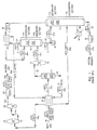
- inlet gas enters the plant at 27°C(80°F) and 3999kPa(a)(580 psia) as stream 31. If the inlet gas contains a concentration of sulfur compounds which would prevent the product streams from meeting specifications, the sulfur compounds are removed by appropriate pretreatment of the feed gas (not illustrated). In addition, the feed stream is usually dehydrated to prevent hydrate (ice) formation under cryogenic conditions. Solid desiccant has typically been used for this purpose.
- the feed stream 31 is cooled in exchanger 10 by heat exchange with cool residue gas at -72°C (-97°F)(stream 34a ) and with separator liquids at -68°C (-91°F)(stream 33a ).
- the decision as to whether to use more than one heat exchanger for the indicated cooling services will depend on a number of factors including, but not limited to. inlet gas flow rate, heat exchanger sizc. stream temperatures, etc.).
- the cooled stream 31a enters separator 11 at -58°C(-73 °F) and 3930kPa(a) (570 psia) where the vapor (stream 32 ) is separated from the condensed liquid (stream 33 ).
- the vapor (stream 32 ) from separator 11 enters a work expansion machine 13 in which mechanical energy is extracted from this portion of the high pressure feed.
- the machine 13 expands the vapor substantially isentropically from a pressure of about 3930 kPa(a) (570 psia) to a pressure of about 2434 kPa(a) (353 psia), with the work expansion cooling the expanded stream 32a to a temperature of approximately -79°C (-110°F).
- the expanded and partially condensed stream 32a is supplied to absorbing section 15b in a lower region of separator/absorber 15.
- the liquid portion of the expanded stream commingles with liquids falling downward from the absorbing section and the combined liquid stream 35 exits the bottom of separator/absorber 15 at -79°C (-111°F).
- the vapor portion of the expanded stream rises upward through the absorbing section and is contacted with cold liquid falling downward to condense and absorb the propane and heavier components.
- the separator/absorber tower 15 is a conventional distillation column containing a plurality of vertically spaced trays, one or more packed beds, or some combination of trays and packing. As is often the case in natural gas processing plants, the separator/absorber tower may consist of two sections.
- the upper section 15a is a separator wherein any vapor contained in the top feed is separated from its corresponding liquid portion, and wherein the vapor rising from the lower distillation or absorbing section 15b is combined with the vapor portion (if any) of the top feed to form the cold distillation stream 34 which exits the top of the tower.
- the lower, absorbing section 15b contains the trays and/or packing and provides the necessary contact between the liquids falling downward and the vapors rising upward to condense and absorb the propane and heavier components.
- the combined liquid stream 35 from the bottom of the separator/absorber 15 is supplied as a cold top column feed (stream 35a ) to deethanizer 17 by pump 16.
- the separator liquid (stream 33 ) is flash expanded to slightly above the 2537 kPa(a)(368 psia) operating pressure of deethanizer 17 by expansion valve 12 , cooling stream 33 to -68°C(-91°F)(stream 33a ) before it provides cooling to the incoming feed gas as described earlier.
- Stream 33b. now at 18°C (65°F) then enters deethanizer 17 at a mid-column feed point to be stripped of its methane and C 2 components.
- the deethanizer tower may also consist of two sections: an upper section 17a wherein any vapor contained in the top feed is separated from its corresponding liquid portion. and wherein the vapor rising from the lower distillation or deethanizing section 17b is combined with the vapor portion (if any) of the top feed to form distillation stream 36 which exits the top of the tower; and a lower, deethanizing section 17b that contains the trays and/or packing to provide the necessary contact between the liquids falling downward and the vapors rising upward.
- the deethanizing section 17b also includes a reboiler 18 which heats and vaporizes a portion of the liquid at the bottom of the column to provide the stripping vapors which flow up the column to strip the liquid product, stream 37, of methane and C 2 components.
- a typical specification for the bottom liquid product is to have an ethane to propane ratio of 0.02:1 on a molar basis.
- the liquid product stream 37 exits the bottom of the deethanizer at 86°C (186°F) and is cooled to 43°C (110°F)(stream 37a) in heat exchanger 19 before flowing to storage.
- deethanizer 17 The operating pressure in deethanizer 17 is maintained slightly above the operating pressure of separator/absorber 15. This allows the deethanizer overhead vapor (stream 36 ) to pressure flow through heat exchanger 20 and thence into the upper section of separator/absorber 15.
- the deethanizer overhead at -30°C (-21 °F) is directed in heat exchange relation with the overhead (stream 34 ) from separator/absorber 15, cooling the stream to -82°C (-116°F)(stream 36a ) and partially condensing it.
- the partially condensed stream is then supplied to the separator section in separator/absorber tower 15 , so that its condensed liquid is separated to become the cold liquid that contacts the vapors rising upward through the absorbing section.
- the distillation stream leaving the top of separator/absorber 15 at -83°C (-117°F) is the cold residue gas stream 34 .
- the residue gas stream passes countercurrently to deethanizer overhead stream 36 in heat exchanger 20 and is warmed to 72°C (97°F)(stream 34a ) as it provides cooling and partial condensation of the deethanizer overhead stream.
- the residue gas is further warmed to 24°C (75°F)(stream 34b) as it passes countercurrently to the incoming feed gas in heat exchanger 10.
- the residue gas is then re-compressed in two stages.
- the first stage is compressor 14 driven by expansion machine 13.
- the second stage is compressor 22 driven by a supplemental power source which compresses the residue gas (stream 34d ) to sales line pressure.
- the residue gas product (stream 34e ) flows to the sales gas pipeline at 43°C (110°F) and 4226 kPa(a) (613 psia).
- FIG. 1 A summary of stream flow rates and energy consumption for the process illustrated in FIG. 1 is set forth in the following table: (FIG.1) Stream Flow Summary - ((Kg.-Lb.)Moles/Hr) Stream Methane Ethane Propane Butanes+ Total 31 (81340) 36896 (4128) 1872 (878) 398 (439) 199 (87840) 39844 32 (80476) 36504 (3792) 1720 (623) 283 (149) 68 (86078) 39045 33 (864) 392 (336) 152 (255) 115 (290) 131 (1762) 799 35 (21.99) 997 (1261) 572 (689) 313 (156) 71 (4359) 1977 36 (3063) 1389 (1581) 717 (121) 55 (7) 3 (4843) 2196 34 (81340) 36896 (4112) 1865 (55) 25 0 (86562) 39264 37 0 (16) 7 (823) 373 (439) 199 (1278) 580 Recoveries
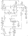
- feed gas enters at 27°C (80°F) and a pressure of 3999 kPa(a)(580 psia) as stream 31.
- the feed stream 31 is cooled in exchanger 10 by heat exchange with cool residue gas at -67°C(-88°F)(stream 34a), with separator liquids at -69°C(-92°F) (stream 33a ), and with separator/absorber liquids at 77°C (-107°F)(stream 35a ).
- the cooled stream 31a enters separator 11 at -61°C(-78°F) and 3930kPa(a)(570 psia) where the vapor (stream 32 ) is separated from the condensed liquid (stream 33 ).
- the vapor (stream 32 ) from separator 11 enters a work expansion machine 13 in which mechanical energy is extracted from this portion of the high pressure feed.
- the machine 13 expands the vapor substantially isentropically from a pressure of about 3930 kPa(a) (570 psia) to a pressure of about 2730 kPa(a) (396 psia) (the operating pressure of separator/absorber 15 ), with the work expansion cooling the expanded stream 32a to a temperature of approximately -77°C (-107°F).
- the expanded and partially condensed stream 32a enters the lower section of separator/absorber 15 .
- the liquid portion of the expanded stream commingles with liquids falling downward from the absorbing section and the combined liquid stream 35 exits the bottom of separator/absorber 15 at -78°C (-108°F).
- the vapor portion of the expanded stream rises upward through the absorbing section and is contacted with cold liquid falling downward to condense and absorb the propane and heavier components.
- the combined liquid stream 35 from the bottom of the separator/absorber 15 is routed to heat exchanger 10 by pump 16 where it (stream 35a) is heated as it provides cooling of the incoming feed gas as described earlier.
- the combined liquid stream is heated to -43°C(-46°F) partially vaporizing stream 35b before it is supplied as a mid-column feed to deethanizer 17.
- the separator liquid (stream 33 ) is flash expanded to slightly above the 2834 kPa(a) (411 psia) operating pressure of deethanizer 17 by expansion valve 12, cooling stream 33 to -69°C (-92°F) (stream 33a ) before it provides cooling to the incoming feed gas as described earlier.
- Stream 33b now at 21°C (70°F), then enters deethanizer 17 at a lower mid-column feed point.
- streams 35b and 33b are stripped of their methane and C 2 components.
- the resulting liquid product stream 37 exits the bottom of the deethanizer at 92°C (198°F) and is cooled to 43°C (110°F)(stream 37a ) in heat exchanger 19 before flowing to storage.
- deethanizer 17 The operating pressure in deethanizer 17 is maintained slightly above the operating pressure of separator/absorber 15. This allows the deethanizer overhead vapor (stream 36 ) to pressure flow through heat exchanger 20 and thence into the upper section of separator/absorber 15.
- the deethanizer overhead at -32°C (-25°F) is directed in heat exchange relation with the overhead (stream 34 ) from separator/absorber 15 , cooling the stream to -80°C (-112°F)(stream 36a ) and partially condensing it.
- the partially condensed stream is then supplied to the separator section in separator/absorber tower 15 where the condensed liquid is separated from the uncondensed vapor.
- the uncondensed vapor combines with the vapor rising from the lower absorbing section to form the cold distillation stream 34 leaving the upper region of separator/absorber 15 .
- the condensed liquid is divided into two portions. One portion, stream 40 , is routed to the lower absorbing section of separator/absorber 15 as the cold liquid that contacts the vapors rising upward through the absorbing section.
- the other portion, stream 39 is supplied to deethanizer 17 as reflux by pump 21, with reflux stream 39a flowing to a top feed point on deethanizer 17 at -80°C (112°F).
- the distillation stream leaving the top of separator/absorber 15 at -81°C (-113°F) is the cold residue gas stream 34 .
- the residue gas stream passes countercurrently to deethanizer overhead stream 36 in heat exchanger 20 and is warmed to -67°C (-88°F)(stream 34a ) as it provides cooling and partial condensation of the deethanizer overhead stream.
- the residue gas is further warmed to 24°C(75°F)(stream 34b ) as it passes countercurrently to the incoming feed gas in heat exchanger 10.
- the residue gas is then re-compressed in two stages.
- the first stage is compressor 14 driven by expansion machine 13 .
- the second stage is compressor 22 driven by a supplemental power source which compresses the residue gas (stream 34d ) to sales line pressure.
- the residue gas product (stream 34e ) flows to the sales gas pipeline at 43°C(110°F) and 4226 kPa(a)(613 psia).
- FIG.2 A summary of stream flow rates and energy consumption for the process illustrated in FIG. 2 is set forth in the table below: (FIG.2) Stream Flow Summary - ((Kg-Lb)Moles/Hr) Stream Methane Ethane Propane Butanes+ Total 31 36896 (81340) 1872 (4128) 398 (878) 199 (439) 39844 (87840) 32 36326 (80084) 1658 (3656) 249 (549) 53 (117) 38754 (85436) 33 570 (1256) 214 (472) 149 (329) 146 (322) 1090 (2404) 35 1033 (2277) 516 (1139) 270 (597) 53 (117) 1897 (4182) 36 1986 (4378) 945 (2084) 61 (135) 0 3037 (6695) 40 1214 (2676) 703 (1549) 46 (102) 0 1994 (4395) 39 383 (845) 222 (489) 15 (32) 0 630 (1388) 34 36856 (81340) 18
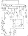
- FIG. 3 Another improvement to the prior art process of FIG. 1 above which is also disclosed in number 5,771,712 is shown in FIG. 3.
- the feed gas composition and conditions considered in the process presented in FIG. 3 are the same as those in FIGS. 1 and 2.
- stream 35a from pump 16 is heated from -80°C (-112°F) to -43°C(-45°F) in heat exchanger 10 as it provides cooling of the incoming feed gas as described previously for FIG. 2.
- the heated stream. stream 35b is then supplied to deethanizer 17 at a top column feed point. entering the tower at -43°C (-45°F) to be stripped of its methane and C 2 components.
- the resulting liquid product stream 37 exits the bottom of the deethanizer at 88°C (191°F) and is cooled to 43°C (110°F)(stream 37a ) in heat exchanger 19 before flowing to storage.
- deethanizer 17 The operating pressure in deethanizer 17 is maintained slightly above the operating pressure of separator/absorber 15. This allows the deethanizer overhead vapor (stream 36 ) to pressure flow through heat exchanger 20 and thence into the upper section of separator/absorber 15.
- the deethanizer overhead at -26°C(-15°F) is directed in heat exchange relation with the overhead (stream 34 ) from separator/absorber 15, cooling the stream to -81°C(-114°F)(stream 36a ) and partially condensing it.
- the partially condensed stream is then supplied to the separator section in separator/absorber tower 15 , so that its condensed liquid is separated to become the cold liquid that contacts the vapors rising upward through the absorbing section.
- the distillation stream leaving the top of separator/absorber 15 at -82°C(-115°F) is the cold residue gas stream 34.
- the residue gas stream passes countercurrently to deethanizer overhead stream 36 in heat exchanger 20 and is warmed to -57°C (-71°F)(stream 34a ) as it provides cooling and partial condensation of the deethanizer overhead stream.
- the residue gas is further warmed to 24°C(75°F) (stream 34b ) as it passes countercurrently to the incoming feed gas in heat exchanger 10 .
- the residue gas is then re-compressed in two stages. The first stage is compressor 14 driven by expansion machine 13 .
- the second stage is compressor 22 driven by a supplemental power source which compresses the residue gas (stream 34d ) to sales line pressure.
- the residue gas product (stream 34e ) flows to the sales gas pipeline at 43°C(110°F) and 4226 kPa(a)(613 psia).
- FIG. 3 A summary of stream flow rates and energy consumptions for the process illustrated in FIG. 3 is set forth in the table below: (FIG.3) Stream Flow Summary ((Kg.-Lb) Moles/Hr) Stream Methane Ethane Propane Butanes+ Total 31 36896 (81340) 1872 (4128) 398 (878) 199 (439) 39844 (87840) 32 36446 (80347) 1699 (3746) 270 (596) 62 (137) 38946 (85861) 33 450 (993) 2266 173 (382) 1353 128 (282) 374 137 (302) 69 898 (1979) 4119 35 (4995) (2983) (826) (153) (9080) 36 2716 (5988) 1519 (3349) 129 (285) 8 (17) 4437 (9781) 34 36896 (81340) 1865 (4112) 7 25 (55) 1 198 39264 (86562) 37 0 (16) 373 (823) (438) 580 (1278) Recoveries Prop
- This absorption cooling effect allows the tower overhead (stream 34 ) to provide the cooling needed in heat exchanger 20 to partially condense the deethanizer overhead (stream 36 ) without operating deethanizer 17 at a pressure significantly higher than that of the separator/absorber 15 .)
- two towers are required to provide the pressure driving force for flow of deethanizer 17 overhead stream 36 through exchanger 20 and to the top feed position of the absorber/separator.
- this top feed, stream 36a is not totally condensed and the vapor portion of it simply combines with the vapor flowing upward from absorber section 15b to form the cold residue, stream 34 .
- the uncondensed portion of stream 36a therefore, does not contribute to the absorption cooling inside absorber/separator 15 .
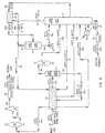
- FIG. 4 illustrates a flow diagram of a process in accordance with application of the present invention to the process of FIG. 1.
- the feed gas composition and conditions considered in the process presented in FIG. 4 are the same as those in FIG. 1. Accordingly, the FIG. 4 process can be compared with that of the FIG. 1 process to illustrate the advantages of the present invention.
- feed gas enters at 27°C (80°F) and a pressure of 3999 kPa(a) (580 psia) as stream 31 .
- the feed stream 31 is cooled in exchanger 10 by heat exchange with cool residue gas at -72°C (-97°F)(stream 34 ) and separator liquids at -69°C(-91°F) (stream 33a ).
- the cooled stream 31a enters separator 11 at -59°C(-73°F) and 3930kPa(a)(570 psia) where the vapor (stream 32 ) is separated from the condensed liquid (stream 33 ).
- the vapor (stream 32 ) from separator 11 enters a work expansion machine 13 in which mechanical energy is extracted from this portion of the high pressure feed.
- the machine 13 expands the vapor substantially isentropically from a pressure of about 3930 kPa(a)(570 psia) to a pressure of about 2448kPa(a)(355 psia)(the operating pressure of deethanizer 17 ), with the work expansion cooling the expanded stream 32a to a temperature of approximately -79°C (-110°F).
- the expanded and partially condensed stream 32a enters deethanizer 17 at an upper mid-column feed position.
- the deethanizer in tower 17 is a conventional distillation column containing a plurality of vertically spaced trays, one or more packed beds, or some combination of trays and packing.
- the deethanizer tower consists of two sections: an upper absorbing (rectification) section 17a that contains the trays and/or packing to provide the necessary contact between the vapor portion of the expanded stream 32a rising upward and cold liquid falling downward to condense and absorb the propane and heavier components; and a lower, stripping section 17b that contains the trays and/or packing to provide the necessary contact between the liquids falling downward and the vapors rising upward.
- the deethanizing section 17b also includes a reboiler 18 which heats and vaporizes a portion of the liquid at the bottom of the column to provide the stripping vapors which flow up the column to strip the liquid product, stream 37 , of methane and C 2 components.
- Stream 32a enters deethanizer 17 at an upper mid-column feed position located in the lower region of absorbing section 17a of deethanizer 17 .
- the liquid portion of the expanded stream commingles with liquids falling downward from the absorbing section 17a and the combined liquid continues downward into the stripping section 17b of deethanizer 17.
- the vapor portion of the expanded stream rises upward through the absorbing section and is contacted with cold liquid falling downward to condense and absorb the propane and heavier components.
- a portion of the distillation vapor (stream 36 ) is withdrawn from the upper region of stripping section 17b .
- This stream is then cooled and partially condensed (stream 36a ) in exchanger 20 by heat exchange with cold deethanizer overhead stream 38 which exits the top of deethanizer 17 at -83°C(-117°F).
- the cold deethanizer overhead stream is warmed to approximately -72°C (-97°F) as it cools stream 36 from -31°C(-24°F) to about -82°C (-116°F) (stream 36a ).
- the operating pressure in reflux separator 15 is maintained slightly below the operating pressure of deethanizer 17 . This allows distillation vapor stream 36 to pressure flow through heat exchanger 20 and thence into the reflux separator 15 wherein the condensed liquid (stream 39 ) is separated from the uncondensed vapor (stream 42 ). The uncondensed vapor stream 42 combines with the warmed deethanizer overhead stream 38a from exchanger 20 to form cool residue gas stream 34 .
- the liquid stream 39 from reflux separator 15 is pumped by pump 21 to a pressure slightly above the operating pressure of deethanizer 17 and the stream ( 39a ) is then supplied as cold top column feed (reflux) to deethanizer 17 .
- This cold liquid feed (reflux) provides the same absorption cooling effect in absorbing (rectification) section 17a of deethanizer 17 as in absorber/separator 15 of the FIG. 1 process while it absorbs and condenses the propane and heavier components flowing upward from below.
- the feed streams are stripped of their methane and C 2 components.
- the resulting liquid product stream 37 exits the bottom of the deethanizer at 84°C(182°F) and is cooled to 43°C(110°F)(stream 37a ) in heat exchanger 19 before flowing to storage.
- the cool residue gas stream 34 is warmed to 24°C (75°F)(stream 34a ) as it passes countercurrently to the incoming feed gas in heat exchanger 10 .
- the residue gas is then re-compressed in two stages.
- the first stage is compressor 14 driven by expansion machine 13 .
- the second stage is compressor 22 driven by a supplemental power source which compresses the residue gas (stream 34c ) to sales line pressure.
- the residue gas product (stream 34d ) flows to the sales gas pipeline at 43°C (110°F) and 4226 kPa(a) (613 psia).
- FIG. 4 A summary of stream flow rates and energy consumption for the process illustrated in FIG. 4 is set forth in the table below: (FIG. 4) Stream Flow Summary -(Kg.-Lb) Moles/Hr) Stream Methane Ethane Propane Butanes+ Total 36896 1872 398 199 39844 31 (81340) (4128) (878) (439) (87840) 36491 1716 279 66 39023 32 (80447) (3782) (616) (146) (86029) 405 156 119 133 821 33 (893) (346) (262) (293) (1811) 1420 728 53 3 2236 36 (3130) (1604) (117) (7) (4930) 423 22 449 42 (932) (49) 0 0 (991) 997 706 53 3 1787 39 (2198) (1555) (117) (7) (3939) 38 36473 (80408) 1843 (4062) 24 (52) 0 38814 (85569) 34 36896 (81
- the FIG. 4 process allows the vapor portion of stream 36a in the FIG. 1 process to bypass exchanger 20 , making it possible to integrate the absorbing section 15b of the absorber/separator 15 of the FIG. 1 process into the deethanizer 17 of the FIG. 4 process as absorbing section 17a . While this reduces slightly (relative to the amount of stream 34 in the FIG. 1 process) the amount of deethanizer overhead stream 38 which flows to heat exchanger 20 in the FIG. 4 process. it allows absorbing section 17a and stripping section 17b to operate at essentially the same pressure. This provides more favorable vapor-liquid equilibrium in the column which more than offsets the slight loss of cooling in exchanger 20. In fact, comparison of the values displayed in Table I for the FIG.
- FIG. 4 process with those displayed in Table IV for the FIG. 4 process shows that the FIG. 4 process achieves 0.3 percentage points better propane recovery than the FIG. 1 process at the same residue compression horsepower.
- the FIG. 4 process reduces the plant capital cost considerably.
- the two fractionation towers of the FIG. 1 process are combined into a single tower in the FIG. 4 process which saves on equipment and installation cost.
- reflux separator 15 of the FIG. 4 process is smaller in diameter than the top separator section 15a of absorber/ separator 15 of the FIG. 1 process, which provides further savings.
- FIG. 5 illustrates a flow diagram of a process in accordance with application of the preferred embodiment of the present invention to the process of FIG. 2.
- the feed gas composition and conditions considered in the process presented in FIG. 5 are the same as those in FIG. 2. Accordingly, the FIG. 5 process can be compared with that of the FIG. 2 process to illustrate the advantages of the present invention.
- feed gas enters at 27°C (80°F) and a pressure of 3999kPa(a)(580 psia) as stream 31 .
- the feed stream 31 is cooled in exchanger 10 by heat exchange with cool residue gas at -68°C(-90°F)(stream 34 ), with separator liquids at -70°C(-94°F) (stream 33a ), and with deethanizer liquids at -78°C(-108°F)(stream 35 ).
- the cooled stream 31a enters separator 11 at -61°C (-78°F) and 3930 kPa(a)(570 psia) where the vapor (stream 32 ) is separated from the condensed liquid (stream 33 ).
- the vapor (stream 32 ) from separator 11 enters a work expansion machine 13 in which mechanical energy is extracted from this portion of the high pressure feed.
- the machine 13 expands the vapor substantially isentropically from a pressure of about 3930 kPa(a) (570 psia) to a pressure of about (2731kPa(a) (396 psia)(the operating pressure of deethanizer 17 ), with the work expansion cooling the expanded stream 32a to a temperature of approximately -77°C (-107°F).
- the expanded and partially condensed stream 32a enters the lower portion of the absorbing (rectification) section of deethanizer 17.
- the liquid portion of the expanded stream commingles with liquids falling downward from the absorbing section and the combined liquid proceeds downward into the stripping section of deethanizer 17 .
- the vapor portion of the expanded stream rises upward through the absorbing section and is contacted with cold liquid falling downward to condense and absorb the propane and heavier components.
- a liquid stream 35 from deethanizer 17 is withdrawn from the upper region of stripping section 17b and is routed to heat exchanger 10 where it is heated as it provides cooling of the incoming feed gas as described earlier.
- the flow of this liquid from the deethanizer is via thermosiphon circulation. but a pump could be used.
- the liquid stream is heated to -49°C (-56°F), partially vaporizing stream 35a before it is returned as a mid-column feed to deethanizer 17, typically in the middle region of the stripping section.
- the separator liquid (stream 33 ) is flash expanded to slightly above the 2731 kPa(a) (396 psia) operating pressure of deethanizer 17 by expansion valve 12 , cooling stream 33 to -70°C (-94°F)(stream 33a ) before it provides cooling to the incoming feed gas as described earlier.
- Stream 33b now at 22°C(71°F), then enters deethanizer 17 at a lower mid-column feed point.
- streams 35a and 33b are stripped of their methane and C 2 components.
- the resulting liquid product stream 37 exits the bottom of the deethanizer at 90°C(194°F) and is cooled to 43°C(110°F)(stream 37a ) in heat exchanger 19 before flowing to storage.
- a portion of the distillation vapor (stream 36 ) is withdrawn from the upper region of the stripping section in deethanizer 17. This stream is then cooled and partially condensed (stream 36a ) by heat exchange with cold deethanizer overhead vapor stream 38 which exits the top of deethanizer 17 at a temperature of about -81°C (-113°F).
- the deethanizer overhead stream is warmed to approximately -67°C (-89°F) as it cools stream 36 from -34°C (-28°F) to about -80°C (-112°F)(stream 36a ).
- the operating pressure in deethanizer 17 is maintained slightly above the operating pressure of reflux separator 15. This allows distillation vapor stream 36 to pressure flow through heat exchanger 20 and thence into reflux separator 15 wherein the condensed liquid (stream 39 ) is separated from the uncondensed vapor (stream 42 ).
- the uncondensed vapor combines with the warmed deethanizer overhead stream 38a from exchanger 20 to form the cool residue gas stream 34 .
- the condensed liquid (stream 39 ) is pumped by pump 21 to a pressure slightly above the operating pressure of deethanizer 17 .
- the pumped stream 39a is then divided into at least two portions.
- stream 40 is routed as top feed (reflux) to deethanizer 17 as the cold liquid that contacts the vapors rising upward through the absorbing (rectification) section.
- stream 41 is supplied to deethanizer 17 at a mid-column feed position located in the upper region of the stripping section to provide partial rectification of distillation vapor stream 36.
- the cool residue gas stream 34 is warmed to 24°C(75°F)(stream 34a ) as it passes countercurrently to the incoming feed gas in heat exchanger 10 .
- the residue gas is then re-compressed in two stages.
- the first stage is compressor 14 driven by expansion machine 13 .
- the second stage is compressor 22 driven by a supplemental power source which compresses the residue gas (stream 34c ) to sales line pressure.
- the residue gas product (stream 34d ) flows to the sales gas pipeline at 43°C(110°F) and 4226 kPa(a) (613 psia).
- FIG. 5 A summary of stream flow rates and energy consumption for the process illustrated in FIG. 5 is set forth in the table below: (FIG.5) Stream Flow Summary - (Kg.-Lb) Moles/Hr) Stream Methane Ethane Propane Butanes+ Total 36896 1872 398 199 39844 31 (81340) (4128) (878) (439) (87840) 32 36318 (80065) 1655 (3650) 248 (546) 53 (116) 38740 (85407) 578 217 150 146 1104 33 (1275) (478) (332) (323) (2433) 1017 505 264 54 1862 35 (2241) (1114) (583) (120) (4105) 1945 916 51 2955 36 (4289) (2019) (113) 0 (6516) 42 383 (845) 20 (44) 1 0 407 (898) 1562 896 50 2548 39 (3444) (1975) (112) 0 (5618) 1210 695 39 1975 40 (2669) 352 (1531
- the column can be operated at a lower pressure resulting in more favorable vapor-liquid equilibrium. This yields an increase in product recovery for this case of 0.56 percentage points at essentially the same recompression power requirement and at a lower deethanizer reboiler duty relative to the FIG. 2 process.
- this single fractionation column system will provide considerable capital cost savings.
- the single fractionation column eliminates the absorber/separator pump for further capital and utility savings.
- FIG. 5 is the preferred embodiment of the present invention.
- FIG. 6 illustrates a flow diagram of a process in accordance with application of the present invention to the process of FIG. 3.
- the feed gas composition and conditions considered in the process presented in FIG. 6 are the same as those in FIG. 3. Accordingly. the FIG. 6 process can be compared with that of the FIG. 3 process to illustrate the advantages of the present invention.
- feed gas enters at 27°C (80°F) and a pressure of 3999 kPa(a) (580 psia) as stream 31 .
- the feed stream 31 is cooled in exchanger 10 by heat exchange with cool residue gas at -56°C (-70°F)(stream 34 ), with separator liquids at -69°C (-93°F) (stream 33a ), and with deethanizer liquids at -80°C(-112°F)(stream 35 ).
- the cooled stream 31a enters separator 11 at -60°C (-75°F) and 3930kPa(a)(570 psia) where the vapor (stream 32 ) is separated from the condensed liquid (stream 33 ).
- the vapor (stream 32 ) from separator 11 enters a work expansion machine 13 in which mechanical energy is extracted from this portion of the high pressure feed.
- the machine 13 expands the vapor substantially isentropically from a pressure of about 3930 kPa(a) (570 psia) to a pressure of about 2558 kPa(a) (371 psia)(the operating pressure of deethanizer 17 ), with the work expansion cooling the expanded stream 32a to a temperature of approximately -78°C (-109°F).
- the expanded and partially condensed stream 32a enters the lower region of the absorbing (rectification) section of deethanizer 17 .
- the liquid portion of the expanded stream commingles with liquids falling downward from the absorbing section and the combined liquid proceeds downward into the stripping section of deethanizer 17 .
- the vapor portion of the expanded stream rises upward through the absorbing section and is contacted with cold liquid falling downward to condense and absorb the propane and heavier components.
- a liquid stream 35 from deethanizer 17 is withdrawn from the upper region of the stripping section and is routed to heat exchanger 10 where it is heated as it provides cooling of the incoming feed gas as described earlier.
- the flow of this liquid from the deethanizer is via thermosiphon circulation, but a pump could be used.
- the liquid stream is heated to -43°C(-46°F) partially vaporizing stream 35a before it is returned as a mid-column feed to deethanizer 17 , typically in the upper region of the stripping section.
- the separator liquid (stream 33 ) is flash expanded to slightly above the 2558kPa(a) (371 psia) operating pressure of deethanizer 17 by expansion valve 12, cooling stream 33 to -69°C(-93°F)(stream 33a ) before it provides cooling to the incoming feed gas as described earlier.
- Stream 33b . now at 22°C(71°F) enters deethanizer 17 at a lower mid-column feed point.
- streams 35a and 33b are stripped of their methane and C 2 components.
- the resulting liquid product stream 37 exits the bottom of the deethanizer at 86°C(187°F) and is cooled to 43°C(110°F)(stream 37a ) in heat exchanger 19 before flowing to storage.
- a portion of the distillation vapor (stream 36 ) is withdrawn from the upper region of the stripping section in deethanizer 17 .
- This stream is then cooled and partially condensed (stream 36a ) by heat exchange with cold deethanizer overhead vapor stream 38 which exits the top of deethanizer 17 at a temperature of about -82°C (-115° F).
- the deethanizer overhead stream is warmed to approximately -65°C (-70°F)as it cools stream 36 from -31°C(-25°F) to about -81°C(-114°F)(stream 36a ).
- the operating pressure in deethanizer 17 is maintained slightly above the operating pressure of reflux separator 15 .
- the uncondensed vapor combines with the warmed deethanizer overhead stream 38a from exchanger 20 to form the cool residue gas stream 34 .
- the condensed liquid (stream 39 ) from reflux separator 15 is pumped by pump 21 to a pressure slightly above the operating pressure of deethanizer 17 .
- the pumped stream 39a is then routed as top feed (reflux) to deethanizer 17 as the cold liquid that contacts the vapors rising upward through the absorbing section.
- the cool residue gas stream 34 is warmed to 24°C(75°F) (stream 34a ) as it passes countercurrently to the incoming feed gas in heat exchanger 10 .
- the residue gas is then re-compressed in two stages.
- the first stage is compressor 14 driven by expansion machine 13 .
- the second stage is compressor 22 driven by a supplemental power source which compresses the residue gas (stream 34c ) to sales line pressure.
- the residue gas product (stream 34d ) flows to the sales gas pipeline at 43°C (110°F) and 4226 kPa(a) (613 psia).
- FIG. 6 A summary of stream flow rates and energy consumption for the process illustrated in FIG. 6 is set forth in the table below: (FIG. 6) Stream Flow Summay - (Lb. Moles/Hr) Stream Methane Ethane Propane Butanes+ Total 36896 1872 398 199 39844 31 (81340) (4128) (878) (439) (87840) 32 36441 (80336) 1697 (3742) 269 (594) 62 (136) 38939 (85844) 455 175 129 137 905 33 (1004) (386) (284) (303) (1996) 2353 1401 375 69 4255 35 (5187) (3089) (826) (152) (9380) 2808 1569 129 8 4580 36 (6191) (3459) (285) (17) (10097) 42 344 (759) 2464 18 (39) 1551 0 129 0 8 366 (806) 4214 39 (5432) (3420) (285) (17) (9291) 38 36896 36552 (8058
- FIG. 6 embodiment of the present invention can achieve essentially the same recovery levels as the FIG. 4 embodiment with slightly lower utility consumptions (residue compression power and deethanizer reboiler duty).
- Comparison of the values in Tables V and VI for the FIG. 5 and FIG. 6 processes shows that the FIG. 6 embodiment of the present invention cannot match the efficiency of the FIG. 5 embodiment, but the simpler arrangement of the FIG. 6 embodiment may offer capital cost advantages that outweigh its higher utility consumptions.
- the choice between the FIGS. 4, 5 and 6 embodiments of the present invention will often depend on factors such as plant size, available equipment, and the economic balance of capital cost versus operating cost.
- the absorbing (rectification) section of the deethanizer it is generally advantageous to design the absorbing (rectification) section of the deethanizer to contain multiple theoretical separation stages.
- the benefits of the present invention can be achieved with as few as one theoretical stage, and it is believed that even the equivalent of a fractional theoretical stage may allow achieving these benefits.
- all or a part of the condensed liquid (stream 39 ) leaving reflux separator 15 and all or a part of the partially condensed stream 32a from work expansion machine 13 can be combined (such as in the piping joining the expansion machine to the deethanizer) and if thoroughly intermingled, the vapors and liquids will mix together and separate in accordance with the relative volatilities of the various components of the total combined streams.
- Such commingling of the two streams shall be considered for the purposes of this invention as constituting an absorbing section.
- the distillation vapor stream 36 is partially condensed and the resulting condensate used to absorb valuable C 3 components and heavier components from the vapors leaving the work expansion machine.
- the present invention is not limited to this embodiment. It may be advantageous, for instance, to treat only a portion of the outlet vapor from the work expansion machine in this manner, or to use only a portion of the condensate as an absorbent, in cases where other design considerations indicate portions of the expansion machine outlet or the condensate should bypass the absorbing section of the deethanizer.
- Feed gas conditions, plant size, available equipment, or other factors may indicate that elimination of work expansion machine 13, or replacement with an alternate expansion device (such as an expansion valve), is feasible, or that total (rather than partial) condensation of distillation vapor stream 36 in heat exchanger 20 is possible or is preferred. It should also be noted that, depending on the composition of the feed gas stream, it may be advantageous to use external refrigeration to provide partial cooling of the distillation vapor stream 36 in exchanger 20.
- distillation vapor stream 36 passes through heat exchanger 20 and into separator 15 without any boost in pressure, the separator shall necessarily assume an operating pressure slightly below the operating pressure of deethanizer 17. In this case, the liquid stream withdrawn from the separator can be pumped to its feed position(s) in the deethanizer.
- An alternative is to provide a booster blower for distillation vapor stream 36 to raise the operating pressure in heat exchanger 20 and separator 15 sufficiently so that the liquid stream 39 can be supplied to deethanizer 17 without pumping.
- FIGS. 4 through 6 are the preferred feed locations for the process operating conditions described. However, the relative locations of the mid-column feeds may vary depending on inlet composition or other factors such as desired recovery levels, etc. Moreover, two or more of the feed streams, or portions thereof, may be combined depending on the relative temperatures and quantities of individual streams, and the combined stream then fed to a mid-column feed position.
- FIGS. 4 through 6 are the preferred embodiments for the compositions and pressure conditions shown. Although individual stream expansion is depicted in particular expansion devices, alternative expansion means may be employed where appropriate. For example, conditions may warrant work expansion of the condensed liquid stream (stream 33 ).
- the present invention provides improved recovery of C 3 components per amount of utility consumption required to operate the process. It also provides for reduced capital expenditure in that all fractionation can be done in a single column.
- An improvement in utility consumption required for operating the deethanizer process may appear in the form of reduced power requirements for compression or re-compression. reduced power requirements for external refrigeration, reduced energy requirements for tower reboilers, or a combination thereof. Alternatively, if desired, increased C 3 component recovery can be obtained for a fixed utility consumption.
Landscapes
- Engineering & Computer Science (AREA)
- Chemical & Material Sciences (AREA)
- Organic Chemistry (AREA)
- Oil, Petroleum & Natural Gas (AREA)
- Thermal Sciences (AREA)
- Physics & Mathematics (AREA)
- Mechanical Engineering (AREA)
- General Engineering & Computer Science (AREA)
- General Chemical & Material Sciences (AREA)
- Chemical Kinetics & Catalysis (AREA)
- Analytical Chemistry (AREA)
- Water Supply & Treatment (AREA)
- Separation By Low-Temperature Treatments (AREA)
- Organic Low-Molecular-Weight Compounds And Preparation Thereof (AREA)
- Production Of Liquid Hydrocarbon Mixture For Refining Petroleum (AREA)
- Transition And Organic Metals Composition Catalysts For Addition Polymerization (AREA)
- Vaporization, Distillation, Condensation, Sublimation, And Cold Traps (AREA)
Applications Claiming Priority (3)
| Application Number | Priority Date | Filing Date | Title |
|---|---|---|---|
| US08/738,321 US5799507A (en) | 1996-10-25 | 1996-10-25 | Hydrocarbon gas processing |
| US738321 | 1996-10-25 | ||
| PCT/US1997/019340 WO1998017609A1 (en) | 1996-10-25 | 1997-10-24 | Hydrocarbon gas processing |
Publications (2)
| Publication Number | Publication Date |
|---|---|
| EP0937016A1 EP0937016A1 (en) | 1999-08-25 |
| EP0937016B1 true EP0937016B1 (en) | 2001-08-16 |
Family
ID=24967510
Family Applications (1)
| Application Number | Title | Priority Date | Filing Date |
|---|---|---|---|
| EP97946304A Expired - Lifetime EP0937016B1 (en) | 1996-10-25 | 1997-10-24 | Hydrocarbon gas processing |
Country Status (27)
| Country | Link |
|---|---|
| US (1) | US5799507A (da) |
| EP (1) | EP0937016B1 (da) |
| JP (1) | JP3221570B2 (da) |
| KR (1) | KR100415950B1 (da) |
| CN (1) | CN1089740C (da) |
| AR (1) | AR009393A1 (da) |
| AT (1) | ATE204250T1 (da) |
| AU (1) | AU728467B2 (da) |
| BR (1) | BR9712373A (da) |
| CA (1) | CA2269462C (da) |
| CO (1) | CO4870777A1 (da) |
| DE (1) | DE69706186T2 (da) |
| DK (1) | DK0937016T3 (da) |
| EA (1) | EA000813B1 (da) |
| EG (1) | EG21661A (da) |
| GE (1) | GEP20012499B (da) |
| GT (1) | GT199700114A (da) |
| ID (1) | ID19316A (da) |
| MY (1) | MY116997A (da) |
| NO (1) | NO325661B1 (da) |
| NZ (1) | NZ335222A (da) |
| PE (1) | PE75899A1 (da) |
| SA (1) | SA98180785B1 (da) |
| TW (1) | TW350021B (da) |
| UA (1) | UA44869C2 (da) |
| UY (1) | UY24761A1 (da) |
| WO (1) | WO1998017609A1 (da) |
Families Citing this family (97)
| Publication number | Priority date | Publication date | Assignee | Title |
|---|---|---|---|---|
| US6098425A (en) * | 1993-10-01 | 2000-08-08 | Stothers; William R. | Thermodynamic separation |
| US6237365B1 (en) | 1998-01-20 | 2001-05-29 | Transcanada Energy Ltd. | Apparatus for and method of separating a hydrocarbon gas into two fractions and a method of retrofitting an existing cryogenic apparatus |
| US6182469B1 (en) * | 1998-12-01 | 2001-02-06 | Elcor Corporation | Hydrocarbon gas processing |
| US6311516B1 (en) * | 2000-01-27 | 2001-11-06 | Ronald D. Key | Process and apparatus for C3 recovery |
| US6278035B1 (en) * | 2000-03-17 | 2001-08-21 | Ronald D. Key | Process for C2 recovery |
| US6453698B2 (en) | 2000-04-13 | 2002-09-24 | Ipsi Llc | Flexible reflux process for high NGL recovery |
| WO2001088447A1 (en) * | 2000-05-18 | 2001-11-22 | Phillips Petroleum Company | Enhanced ngl recovery utilizing refrigeration and reflux from lng plants |
| US6401486B1 (en) * | 2000-05-18 | 2002-06-11 | Rong-Jwyn Lee | Enhanced NGL recovery utilizing refrigeration and reflux from LNG plants |
| AU9491401A (en) * | 2000-10-02 | 2002-04-15 | Elcor Corp | Hydrocarbon gas processing |
| US6712880B2 (en) | 2001-03-01 | 2004-03-30 | Abb Lummus Global, Inc. | Cryogenic process utilizing high pressure absorber column |
| US6526777B1 (en) | 2001-04-20 | 2003-03-04 | Elcor Corporation | LNG production in cryogenic natural gas processing plants |
| UA76750C2 (uk) * | 2001-06-08 | 2006-09-15 | Елккорп | Спосіб зрідження природного газу (варіанти) |
| US6742358B2 (en) * | 2001-06-08 | 2004-06-01 | Elkcorp | Natural gas liquefaction |
| US6425266B1 (en) | 2001-09-24 | 2002-07-30 | Air Products And Chemicals, Inc. | Low temperature hydrocarbon gas separation process |
| US6823692B1 (en) | 2002-02-11 | 2004-11-30 | Abb Lummus Global Inc. | Carbon dioxide reduction scheme for NGL processes |
| US6931889B1 (en) * | 2002-04-19 | 2005-08-23 | Abb Lummus Global, Randall Gas Technologies | Cryogenic process for increased recovery of hydrogen |
| CA2388266C (en) | 2002-05-30 | 2008-08-26 | Propak Systems Ltd. | System and method for liquefied petroleum gas recovery |
| JP4193438B2 (ja) | 2002-07-30 | 2008-12-10 | ソニー株式会社 | 半導体装置の製造方法 |
| US6945075B2 (en) * | 2002-10-23 | 2005-09-20 | Elkcorp | Natural gas liquefaction |
| US7069744B2 (en) * | 2002-12-19 | 2006-07-04 | Abb Lummus Global Inc. | Lean reflux-high hydrocarbon recovery process |
| EA008462B1 (ru) * | 2003-02-25 | 2007-06-29 | Ортлофф Инджинирс, Лтд. | Переработка углеводородного газа |
| US6889523B2 (en) | 2003-03-07 | 2005-05-10 | Elkcorp | LNG production in cryogenic natural gas processing plants |
| US6662589B1 (en) | 2003-04-16 | 2003-12-16 | Air Products And Chemicals, Inc. | Integrated high pressure NGL recovery in the production of liquefied natural gas |
| US7036337B2 (en) * | 2003-08-29 | 2006-05-02 | Wylie Companies, Inc | Recovery of hydrogen from refinery and petrochemical light ends streams |
| US7155931B2 (en) * | 2003-09-30 | 2007-01-02 | Ortloff Engineers, Ltd. | Liquefied natural gas processing |
| US7159417B2 (en) * | 2004-03-18 | 2007-01-09 | Abb Lummus Global, Inc. | Hydrocarbon recovery process utilizing enhanced reflux streams |
| US7204100B2 (en) * | 2004-05-04 | 2007-04-17 | Ortloff Engineers, Ltd. | Natural gas liquefaction |
| US7216507B2 (en) * | 2004-07-01 | 2007-05-15 | Ortloff Engineers, Ltd. | Liquefied natural gas processing |
| RU2272973C1 (ru) * | 2004-09-24 | 2006-03-27 | Салават Зайнетдинович Имаев | Способ низкотемпературной сепарации газа (варианты) |
| WO2006089948A1 (en) * | 2005-02-24 | 2006-08-31 | Twister B.V. | Method and system for cooling a natural gas stream and separating the cooled stream into various fractions |
| US20070061950A1 (en) * | 2005-03-29 | 2007-03-22 | Terry Delonas | Lipowear |
| US20090064712A1 (en) * | 2005-04-12 | 2009-03-12 | Cornelis Buijs | Method and Apparatus for Liquefying a Natural Gas Stream |
| EA013357B1 (ru) * | 2005-04-20 | 2010-04-30 | Флуор Текнолоджиз Корпорейшн | Способ и устройство для извлечения газоконденсатных жидкостей и сжижения природного газа |
| US9080810B2 (en) * | 2005-06-20 | 2015-07-14 | Ortloff Engineers, Ltd. | Hydrocarbon gas processing |
| US20070261437A1 (en) * | 2006-05-12 | 2007-11-15 | Boonstra Eric F | Enhanced process for the purification of anhydrous hydrogen chloride gas |
| KR101407771B1 (ko) * | 2006-06-02 | 2014-06-16 | 오르트로프 엔지니어스, 리미티드 | 액화 천연 가스 처리 |
| US8677780B2 (en) * | 2006-07-10 | 2014-03-25 | Fluor Technologies Corporation | Configurations and methods for rich gas conditioning for NGL recovery |
| JP2008050303A (ja) * | 2006-08-24 | 2008-03-06 | Mitsubishi Chemicals Corp | 蒸留系の制御方法、制御システム及び制御プログラム |
| US7777088B2 (en) * | 2007-01-10 | 2010-08-17 | Pilot Energy Solutions, Llc | Carbon dioxide fractionalization process |
| US8590340B2 (en) * | 2007-02-09 | 2013-11-26 | Ortoff Engineers, Ltd. | Hydrocarbon gas processing |
| US9869510B2 (en) * | 2007-05-17 | 2018-01-16 | Ortloff Engineers, Ltd. | Liquefied natural gas processing |
| US8919148B2 (en) * | 2007-10-18 | 2014-12-30 | Ortloff Engineers, Ltd. | Hydrocarbon gas processing |
| US9243842B2 (en) | 2008-02-15 | 2016-01-26 | Black & Veatch Corporation | Combined synthesis gas separation and LNG production method and system |
| US8209997B2 (en) * | 2008-05-16 | 2012-07-03 | Lummus Technology, Inc. | ISO-pressure open refrigeration NGL recovery |
| US20090282865A1 (en) | 2008-05-16 | 2009-11-19 | Ortloff Engineers, Ltd. | Liquefied Natural Gas and Hydrocarbon Gas Processing |
| US20090293537A1 (en) * | 2008-05-27 | 2009-12-03 | Ameringer Greg E | NGL Extraction From Natural Gas |
| US8584488B2 (en) * | 2008-08-06 | 2013-11-19 | Ortloff Engineers, Ltd. | Liquefied natural gas production |
| WO2010027986A1 (en) * | 2008-09-03 | 2010-03-11 | Ameringer Greg E | Ngl extraction from liquefied natural gas |
| US9939195B2 (en) * | 2009-02-17 | 2018-04-10 | Ortloff Engineers, Ltd. | Hydrocarbon gas processing including a single equipment item processing assembly |
| US9074814B2 (en) * | 2010-03-31 | 2015-07-07 | Ortloff Engineers, Ltd. | Hydrocarbon gas processing |
| US9933207B2 (en) * | 2009-02-17 | 2018-04-03 | Ortloff Engineers, Ltd. | Hydrocarbon gas processing |
| US9052136B2 (en) * | 2010-03-31 | 2015-06-09 | Ortloff Engineers, Ltd. | Hydrocarbon gas processing |
| US9080811B2 (en) * | 2009-02-17 | 2015-07-14 | Ortloff Engineers, Ltd | Hydrocarbon gas processing |
| EA022672B1 (ru) * | 2009-02-17 | 2016-02-29 | Ортлофф Инджинирс, Лтд. | Обработка углеводородного газа |
| US9052137B2 (en) | 2009-02-17 | 2015-06-09 | Ortloff Engineers, Ltd. | Hydrocarbon gas processing |
| US8881549B2 (en) * | 2009-02-17 | 2014-11-11 | Ortloff Engineers, Ltd. | Hydrocarbon gas processing |
| US8434325B2 (en) | 2009-05-15 | 2013-05-07 | Ortloff Engineers, Ltd. | Liquefied natural gas and hydrocarbon gas processing |
| US20100287982A1 (en) | 2009-05-15 | 2010-11-18 | Ortloff Engineers, Ltd. | Liquefied Natural Gas and Hydrocarbon Gas Processing |
| MY157703A (en) * | 2009-06-11 | 2016-07-15 | Ortloff Engineers Ltd | Hydrocarbon gas processing |
| US20110067443A1 (en) * | 2009-09-21 | 2011-03-24 | Ortloff Engineers, Ltd. | Hydrocarbon Gas Processing |
| US9021832B2 (en) | 2010-01-14 | 2015-05-05 | Ortloff Engineers, Ltd. | Hydrocarbon gas processing |
| US9068774B2 (en) * | 2010-03-31 | 2015-06-30 | Ortloff Engineers, Ltd. | Hydrocarbon gas processing |
| US9057558B2 (en) * | 2010-03-31 | 2015-06-16 | Ortloff Engineers, Ltd. | Hydrocarbon gas processing including a single equipment item processing assembly |
| US10113127B2 (en) | 2010-04-16 | 2018-10-30 | Black & Veatch Holding Company | Process for separating nitrogen from a natural gas stream with nitrogen stripping in the production of liquefied natural gas |
| AU2011261670B2 (en) | 2010-06-03 | 2014-08-21 | Uop Llc | Hydrocarbon gas processing |
| AU2011272754B2 (en) * | 2010-07-01 | 2016-02-11 | Black & Veatch Holding Company | Methods and systems for recovering liquified petroleum gas from natural gas |
| US8635885B2 (en) | 2010-10-15 | 2014-01-28 | Fluor Technologies Corporation | Configurations and methods of heating value control in LNG liquefaction plant |
| US9777960B2 (en) | 2010-12-01 | 2017-10-03 | Black & Veatch Holding Company | NGL recovery from natural gas using a mixed refrigerant |
| US10852060B2 (en) * | 2011-04-08 | 2020-12-01 | Pilot Energy Solutions, Llc | Single-unit gas separation process having expanded, post-separation vent stream |
| KR101248232B1 (ko) * | 2011-12-23 | 2013-03-27 | 재단법인 포항산업과학연구원 | 병렬 부대설비의 이상 진단 방법 및 시스템 |
| US10139157B2 (en) | 2012-02-22 | 2018-11-27 | Black & Veatch Holding Company | NGL recovery from natural gas using a mixed refrigerant |
| CN104736504A (zh) * | 2012-07-26 | 2015-06-24 | 氟石科技公司 | 用于深度的进料气体烃露点调整的构造和方法 |
| WO2014116273A1 (en) * | 2013-01-25 | 2014-07-31 | H R D Corporation | Method of high shear comminution of solids |
| US9581385B2 (en) | 2013-05-15 | 2017-02-28 | Linde Engineering North America Inc. | Methods for separating hydrocarbon gases |
| JP6591983B2 (ja) | 2013-09-11 | 2019-10-16 | オートロフ・エンジニアーズ・リミテッド | 炭化水素ガス処理 |
| WO2015038287A1 (en) | 2013-09-11 | 2015-03-19 | Ortloff Engineers, Ltd. | Hydrocarbon gas processing |
| US9790147B2 (en) | 2013-09-11 | 2017-10-17 | Ortloff Engineers, Ltd. | Hydrocarbon processing |
| US10563913B2 (en) | 2013-11-15 | 2020-02-18 | Black & Veatch Holding Company | Systems and methods for hydrocarbon refrigeration with a mixed refrigerant cycle |
| CA2942675C (en) | 2014-03-14 | 2024-01-09 | Lummus Technology Inc. | Process and apparatus for heavy hydrocarbon removal from lean natural gas before liquefaction |
| US9574822B2 (en) | 2014-03-17 | 2017-02-21 | Black & Veatch Corporation | Liquefied natural gas facility employing an optimized mixed refrigerant system |
| US10551118B2 (en) | 2016-08-26 | 2020-02-04 | Ortloff Engineers, Ltd. | Hydrocarbon gas processing |
| US10533794B2 (en) | 2016-08-26 | 2020-01-14 | Ortloff Engineers, Ltd. | Hydrocarbon gas processing |
| US10551119B2 (en) * | 2016-08-26 | 2020-02-04 | Ortloff Engineers, Ltd. | Hydrocarbon gas processing |
| US11402155B2 (en) | 2016-09-06 | 2022-08-02 | Lummus Technology Inc. | Pretreatment of natural gas prior to liquefaction |
| FR3066491B1 (fr) * | 2017-05-18 | 2019-07-12 | Technip France | Procede de recuperation d'un courant d'hydrocarbures en c2+ dans un gaz residuel de raffinerie et installation associee |
| US11428465B2 (en) | 2017-06-01 | 2022-08-30 | Uop Llc | Hydrocarbon gas processing |
| US11543180B2 (en) | 2017-06-01 | 2023-01-03 | Uop Llc | Hydrocarbon gas processing |
| US12504227B2 (en) | 2018-08-27 | 2025-12-23 | Bcck Holding Company | System and method for natural gas liquid production with flexible ethane recovery or rejection |
| US11015865B2 (en) | 2018-08-27 | 2021-05-25 | Bcck Holding Company | System and method for natural gas liquid production with flexible ethane recovery or rejection |
| US11473837B2 (en) | 2018-08-31 | 2022-10-18 | Uop Llc | Gas subcooled process conversion to recycle split vapor for recovery of ethane and propane |
| MY195957A (en) * | 2019-03-11 | 2023-02-27 | Uop Llc | Hydrocarbon Gas Processing |
| US11643604B2 (en) | 2019-10-18 | 2023-05-09 | Uop Llc | Hydrocarbon gas processing |
| JP7741823B2 (ja) * | 2020-06-03 | 2025-09-18 | チャート・エナジー・アンド・ケミカルズ,インコーポレーテッド | ガスストリーム成分除去システムおよび方法 |
| US20230375265A1 (en) * | 2022-05-17 | 2023-11-23 | Gas Liquids Engineering Ltd. | Gas processing methodology utilizing reflux and additionally synthesized stream optimization |
| US20230375263A1 (en) * | 2022-05-17 | 2023-11-23 | Gas Liquids Engineering Ltd. | Gas processing methodology utilizing reflux and additionally synthesized stream optimization |
| US20240318910A1 (en) * | 2023-03-22 | 2024-09-26 | Bcck Holding Company | System and method for improving propane recovery and ethane rejection in a gsp/ expander system |
| US20240417639A1 (en) * | 2023-06-19 | 2024-12-19 | Air Products And Chemicals, Inc. | Apparatus and Process for Removal of Heavy Hydrocarbons from a Feed Gas |
Family Cites Families (17)
| Publication number | Priority date | Publication date | Assignee | Title |
|---|---|---|---|---|
| US4171964A (en) * | 1976-06-21 | 1979-10-23 | The Ortloff Corporation | Hydrocarbon gas processing |
| US4157904A (en) * | 1976-08-09 | 1979-06-12 | The Ortloff Corporation | Hydrocarbon gas processing |
| SU656648A1 (ru) * | 1976-10-12 | 1979-04-15 | Всесоюзный научно-исследовательский институт природных газов | Способ разделени углеводородных смесей |
| US4251249A (en) * | 1977-01-19 | 1981-02-17 | The Randall Corporation | Low temperature process for separating propane and heavier hydrocarbons from a natural gas stream |
| US4278457A (en) * | 1977-07-14 | 1981-07-14 | Ortloff Corporation | Hydrocarbon gas processing |
| USRE33408E (en) * | 1983-09-29 | 1990-10-30 | Exxon Production Research Company | Process for LPG recovery |
| US4519824A (en) * | 1983-11-07 | 1985-05-28 | The Randall Corporation | Hydrocarbon gas separation |
| FR2571129B1 (fr) * | 1984-09-28 | 1988-01-29 | Technip Cie | Procede et installation de fractionnement cryogenique de charges gazeuses |
| US4617039A (en) * | 1984-11-19 | 1986-10-14 | Pro-Quip Corporation | Separating hydrocarbon gases |
| US4687499A (en) * | 1986-04-01 | 1987-08-18 | Mcdermott International Inc. | Process for separating hydrocarbon gas constituents |
| US4854955A (en) * | 1988-05-17 | 1989-08-08 | Elcor Corporation | Hydrocarbon gas processing |
| US4869740A (en) * | 1988-05-17 | 1989-09-26 | Elcor Corporation | Hydrocarbon gas processing |
| US4889545A (en) * | 1988-11-21 | 1989-12-26 | Elcor Corporation | Hydrocarbon gas processing |
| US4895584A (en) * | 1989-01-12 | 1990-01-23 | Pro-Quip Corporation | Process for C2 recovery |
| US5275005A (en) * | 1992-12-01 | 1994-01-04 | Elcor Corporation | Gas processing |
| US5568737A (en) * | 1994-11-10 | 1996-10-29 | Elcor Corporation | Hydrocarbon gas processing |
| BR9609099A (pt) * | 1995-06-07 | 1999-02-02 | Elcor Corp | Processo e dispositivo para a separação de um fluxo de gás |
-
1996
- 1996-10-25 US US08/738,321 patent/US5799507A/en not_active Expired - Lifetime
-
1997
- 1997-10-24 EP EP97946304A patent/EP0937016B1/en not_active Expired - Lifetime
- 1997-10-24 GE GEAP19974762A patent/GEP20012499B/en unknown
- 1997-10-24 NZ NZ335222A patent/NZ335222A/xx not_active IP Right Cessation
- 1997-10-24 DK DK97946304T patent/DK0937016T3/da active
- 1997-10-24 KR KR10-1999-7003549A patent/KR100415950B1/ko not_active Expired - Fee Related
- 1997-10-24 JP JP51966598A patent/JP3221570B2/ja not_active Expired - Fee Related
- 1997-10-24 AT AT97946304T patent/ATE204250T1/de not_active IP Right Cessation
- 1997-10-24 WO PCT/US1997/019340 patent/WO1998017609A1/en not_active Ceased
- 1997-10-24 CA CA002269462A patent/CA2269462C/en not_active Expired - Lifetime
- 1997-10-24 BR BR9712373-0A patent/BR9712373A/pt not_active IP Right Cessation
- 1997-10-24 GT GT199700114A patent/GT199700114A/es unknown
- 1997-10-24 DE DE69706186T patent/DE69706186T2/de not_active Expired - Lifetime
- 1997-10-24 MY MYPI97005016A patent/MY116997A/en unknown
- 1997-10-24 UA UA99052835A patent/UA44869C2/uk unknown
- 1997-10-24 CN CN97199161A patent/CN1089740C/zh not_active Expired - Fee Related
- 1997-10-24 EA EA199900405A patent/EA000813B1/ru not_active IP Right Cessation
- 1997-10-24 AU AU51503/98A patent/AU728467B2/en not_active Expired
- 1997-10-25 EG EG112497A patent/EG21661A/xx active
- 1997-10-27 CO CO97062829A patent/CO4870777A1/es unknown
- 1997-10-27 UY UY24761A patent/UY24761A1/es not_active IP Right Cessation
- 1997-10-27 PE PE1997000958A patent/PE75899A1/es not_active IP Right Cessation
- 1997-10-27 ID IDP973531A patent/ID19316A/id unknown
- 1997-10-27 AR ARP970104968A patent/AR009393A1/es active IP Right Grant
- 1997-12-04 TW TW086118252A patent/TW350021B/zh not_active IP Right Cessation
-
1998
- 1998-01-14 SA SA98180785A patent/SA98180785B1/ar unknown
-
1999
- 1999-04-23 NO NO19991955A patent/NO325661B1/no not_active IP Right Cessation
Non-Patent Citations (1)
| Title |
|---|
| None * |
Also Published As
Similar Documents
| Publication | Publication Date | Title |
|---|---|---|
| EP0937016B1 (en) | Hydrocarbon gas processing | |
| CA2223042C (en) | Hydrocarbon gas processing | |
| US7191617B2 (en) | Hydrocarbon gas processing | |
| US5890378A (en) | Hydrocarbon gas processing | |
| CA2676151C (en) | Hydrocarbon gas processing | |
| CA2204264C (en) | Hydrocarbon gas processing | |
| US5983664A (en) | Hydrocarbon gas processing | |
| US8919148B2 (en) | Hydrocarbon gas processing | |
| AU2010295869B2 (en) | Hydrocarbon gas processing | |
| US20020166336A1 (en) | Hydrocarbon gas processing | |
| NZ500066A (en) | Process for separating hydrocarbon components from a gas stream containing methane, C2 and C3 and heavier hydrocarbons | |
| AU710661C (en) | Hydrocarbon gas processing |
Legal Events
| Date | Code | Title | Description |
|---|---|---|---|
| PUAI | Public reference made under article 153(3) epc to a published international application that has entered the european phase |
Free format text: ORIGINAL CODE: 0009012 |
|
| 17P | Request for examination filed |
Effective date: 19990414 |
|
| AK | Designated contracting states |
Kind code of ref document: A1 Designated state(s): AT BE CH DE DK ES FI FR GB GR IE IT LI LU MC NL PT SE |
|
| AX | Request for extension of the european patent |
Free format text: LT PAYMENT 19990414 |
|
| RIN1 | Information on inventor provided before grant (corrected) |
Inventor name: CUELLAR, KYLE, T. Inventor name: HUDSON, HANK, M. Inventor name: WILKINSON, JOHN, D. |
|
| 17Q | First examination report despatched |
Effective date: 19991105 |
|
| GRAG | Despatch of communication of intention to grant |
Free format text: ORIGINAL CODE: EPIDOS AGRA |
|
| GRAG | Despatch of communication of intention to grant |
Free format text: ORIGINAL CODE: EPIDOS AGRA |
|
| GRAG | Despatch of communication of intention to grant |
Free format text: ORIGINAL CODE: EPIDOS AGRA |
|
| GRAG | Despatch of communication of intention to grant |
Free format text: ORIGINAL CODE: EPIDOS AGRA |
|
| GRAH | Despatch of communication of intention to grant a patent |
Free format text: ORIGINAL CODE: EPIDOS IGRA |
|
| GRAH | Despatch of communication of intention to grant a patent |
Free format text: ORIGINAL CODE: EPIDOS IGRA |
|
| GRAH | Despatch of communication of intention to grant a patent |
Free format text: ORIGINAL CODE: EPIDOS IGRA |
|
| GRAA | (expected) grant |
Free format text: ORIGINAL CODE: 0009210 |
|
| AK | Designated contracting states |
Kind code of ref document: B1 Designated state(s): AT BE CH DE DK ES FI FR GB GR IE IT LI LU MC NL PT SE |
|
| AX | Request for extension of the european patent |
Free format text: LT PAYMENT 19990414 |
|
| LTIE | Lt: invalidation of european patent or patent extension | ||
| PG25 | Lapsed in a contracting state [announced via postgrant information from national office to epo] |
Ref country code: LI Free format text: LAPSE BECAUSE OF FAILURE TO SUBMIT A TRANSLATION OF THE DESCRIPTION OR TO PAY THE FEE WITHIN THE PRESCRIBED TIME-LIMIT Effective date: 20010816 Ref country code: IT Free format text: LAPSE BECAUSE OF FAILURE TO SUBMIT A TRANSLATION OF THE DESCRIPTION OR TO PAY THE FEE WITHIN THE PRE;WARNING: LAPSES OF ITALIAN PATENTS WITH EFFECTIVE DATE BEFORE 2007 MAY HAVE OCCURRED AT ANY TIME BEFORE 2007. THE CORRECT EFFECTIVE DATE MAY BE DIFFERENT FROM THE ONE RECORDED.SCRIBED TIME-LIMIT Effective date: 20010816 Ref country code: FI Free format text: LAPSE BECAUSE OF FAILURE TO SUBMIT A TRANSLATION OF THE DESCRIPTION OR TO PAY THE FEE WITHIN THE PRESCRIBED TIME-LIMIT Effective date: 20010816 Ref country code: CH Free format text: LAPSE BECAUSE OF FAILURE TO SUBMIT A TRANSLATION OF THE DESCRIPTION OR TO PAY THE FEE WITHIN THE PRESCRIBED TIME-LIMIT Effective date: 20010816 Ref country code: BE Free format text: LAPSE BECAUSE OF FAILURE TO SUBMIT A TRANSLATION OF THE DESCRIPTION OR TO PAY THE FEE WITHIN THE PRESCRIBED TIME-LIMIT Effective date: 20010816 Ref country code: AT Free format text: LAPSE BECAUSE OF FAILURE TO SUBMIT A TRANSLATION OF THE DESCRIPTION OR TO PAY THE FEE WITHIN THE PRESCRIBED TIME-LIMIT Effective date: 20010816 |
|
| REF | Corresponds to: |
Ref document number: 204250 Country of ref document: AT Date of ref document: 20010915 Kind code of ref document: T |
|
| REG | Reference to a national code |
Ref country code: CH Ref legal event code: EP |
|
| REF | Corresponds to: |
Ref document number: 69706186 Country of ref document: DE Date of ref document: 20010920 |
|
| REG | Reference to a national code |
Ref country code: DK Ref legal event code: T3 |
|
| REG | Reference to a national code |
Ref country code: IE Ref legal event code: FG4D |
|
| PG25 | Lapsed in a contracting state [announced via postgrant information from national office to epo] |
Ref country code: MC Free format text: LAPSE BECAUSE OF NON-PAYMENT OF DUE FEES Effective date: 20011024 Ref country code: LU Free format text: LAPSE BECAUSE OF NON-PAYMENT OF DUE FEES Effective date: 20011024 Ref country code: IE Free format text: LAPSE BECAUSE OF FAILURE TO SUBMIT A TRANSLATION OF THE DESCRIPTION OR TO PAY THE FEE WITHIN THE PRESCRIBED TIME-LIMIT Effective date: 20011024 |
|
| PG25 | Lapsed in a contracting state [announced via postgrant information from national office to epo] |
Ref country code: SE Free format text: LAPSE BECAUSE OF FAILURE TO SUBMIT A TRANSLATION OF THE DESCRIPTION OR TO PAY THE FEE WITHIN THE PRESCRIBED TIME-LIMIT Effective date: 20011116 Ref country code: PT Free format text: LAPSE BECAUSE OF FAILURE TO SUBMIT A TRANSLATION OF THE DESCRIPTION OR TO PAY THE FEE WITHIN THE PRESCRIBED TIME-LIMIT Effective date: 20011116 |
|
| PG25 | Lapsed in a contracting state [announced via postgrant information from national office to epo] |
Ref country code: GR Free format text: LAPSE BECAUSE OF FAILURE TO SUBMIT A TRANSLATION OF THE DESCRIPTION OR TO PAY THE FEE WITHIN THE PRESCRIBED TIME-LIMIT Effective date: 20011117 |
|
| REG | Reference to a national code |
Ref country code: GB Ref legal event code: IF02 |
|
| ET | Fr: translation filed | ||
| PG25 | Lapsed in a contracting state [announced via postgrant information from national office to epo] |
Ref country code: ES Free format text: LAPSE BECAUSE OF FAILURE TO SUBMIT A TRANSLATION OF THE DESCRIPTION OR TO PAY THE FEE WITHIN THE PRESCRIBED TIME-LIMIT Effective date: 20020228 |
|
| REG | Reference to a national code |
Ref country code: CH Ref legal event code: PL |
|
| PLBE | No opposition filed within time limit |
Free format text: ORIGINAL CODE: 0009261 |
|
| STAA | Information on the status of an ep patent application or granted ep patent |
Free format text: STATUS: NO OPPOSITION FILED WITHIN TIME LIMIT |
|
| 26N | No opposition filed | ||
| REG | Reference to a national code |
Ref country code: IE Ref legal event code: MM4A |
|
| NLT1 | Nl: modifications of names registered in virtue of documents presented to the patent office pursuant to art. 16 a, paragraph 1 |
Owner name: ELKCORP |
|
| REG | Reference to a national code |
Ref country code: FR Ref legal event code: CD |
|
| NLS | Nl: assignments of ep-patents |
Owner name: ORTLOFF ENGINEERS, LTD. Effective date: 20070625 |
|
| REG | Reference to a national code |
Ref country code: FR Ref legal event code: TP |
|
| REG | Reference to a national code |
Ref country code: GB Ref legal event code: 732E |
|
| PGFP | Annual fee paid to national office [announced via postgrant information from national office to epo] |
Ref country code: DK Payment date: 20121025 Year of fee payment: 16 |
|
| PGFP | Annual fee paid to national office [announced via postgrant information from national office to epo] |
Ref country code: NL Payment date: 20121024 Year of fee payment: 16 |
|
| REG | Reference to a national code |
Ref country code: NL Ref legal event code: V1 Effective date: 20140501 |
|
| REG | Reference to a national code |
Ref country code: DK Ref legal event code: EBP Effective date: 20131031 |
|
| PG25 | Lapsed in a contracting state [announced via postgrant information from national office to epo] |
Ref country code: NL Free format text: LAPSE BECAUSE OF NON-PAYMENT OF DUE FEES Effective date: 20140501 |
|
| PG25 | Lapsed in a contracting state [announced via postgrant information from national office to epo] |
Ref country code: DK Free format text: LAPSE BECAUSE OF NON-PAYMENT OF DUE FEES Effective date: 20131031 |
|
| REG | Reference to a national code |
Ref country code: FR Ref legal event code: PLFP Year of fee payment: 19 |
|
| REG | Reference to a national code |
Ref country code: FR Ref legal event code: PLFP Year of fee payment: 20 |
|
| PGFP | Annual fee paid to national office [announced via postgrant information from national office to epo] |
Ref country code: FR Payment date: 20160926 Year of fee payment: 20 |
|
| PGFP | Annual fee paid to national office [announced via postgrant information from national office to epo] |
Ref country code: GB Payment date: 20161026 Year of fee payment: 20 Ref country code: DE Payment date: 20161031 Year of fee payment: 20 |
|
| REG | Reference to a national code |
Ref country code: DE Ref legal event code: R071 Ref document number: 69706186 Country of ref document: DE |
|
| REG | Reference to a national code |
Ref country code: GB Ref legal event code: PE20 Expiry date: 20171023 |
|
| PG25 | Lapsed in a contracting state [announced via postgrant information from national office to epo] |
Ref country code: GB Free format text: LAPSE BECAUSE OF EXPIRATION OF PROTECTION Effective date: 20171023 |