EP0937543A2 - Verfahren zum Schleifen einer Endhülse für schräge PC Steckverbinder - Google Patents
Verfahren zum Schleifen einer Endhülse für schräge PC Steckverbinder Download PDFInfo
- Publication number
- EP0937543A2 EP0937543A2 EP99301345A EP99301345A EP0937543A2 EP 0937543 A2 EP0937543 A2 EP 0937543A2 EP 99301345 A EP99301345 A EP 99301345A EP 99301345 A EP99301345 A EP 99301345A EP 0937543 A2 EP0937543 A2 EP 0937543A2
- Authority
- EP
- European Patent Office
- Prior art keywords
- ferrule
- grinding
- face
- leading end
- ground
- Prior art date
- Legal status (The legal status is an assumption and is not a legal conclusion. Google has not performed a legal analysis and makes no representation as to the accuracy of the status listed.)
- Withdrawn
Links
Images


Classifications
-
- G—PHYSICS
- G02—OPTICS
- G02B—OPTICAL ELEMENTS, SYSTEMS OR APPARATUS
- G02B6/00—Light guides; Structural details of arrangements comprising light guides and other optical elements, e.g. couplings
- G02B6/24—Coupling light guides
- G02B6/25—Preparing the ends of light guides for coupling, e.g. cutting
-
- B—PERFORMING OPERATIONS; TRANSPORTING
- B24—GRINDING; POLISHING
- B24B—MACHINES, DEVICES, OR PROCESSES FOR GRINDING OR POLISHING; DRESSING OR CONDITIONING OF ABRADING SURFACES; FEEDING OF GRINDING, POLISHING, OR LAPPING AGENTS
- B24B19/00—Single-purpose machines or devices for particular grinding operations not covered by any other main group
- B24B19/22—Single-purpose machines or devices for particular grinding operations not covered by any other main group characterised by a special design with respect to properties of the material of non-metallic articles to be ground
- B24B19/226—Single-purpose machines or devices for particular grinding operations not covered by any other main group characterised by a special design with respect to properties of the material of non-metallic articles to be ground of the ends of optical fibres
-
- G—PHYSICS
- G02—OPTICS
- G02B—OPTICAL ELEMENTS, SYSTEMS OR APPARATUS
- G02B6/00—Light guides; Structural details of arrangements comprising light guides and other optical elements, e.g. couplings
- G02B6/24—Coupling light guides
- G02B6/36—Mechanical coupling means
- G02B6/38—Mechanical coupling means having fibre to fibre mating means
- G02B6/3807—Dismountable connectors, i.e. comprising plugs
- G02B6/381—Dismountable connectors, i.e. comprising plugs of the ferrule type, e.g. fibre ends embedded in ferrules, connecting a pair of fibres
- G02B6/3818—Dismountable connectors, i.e. comprising plugs of the ferrule type, e.g. fibre ends embedded in ferrules, connecting a pair of fibres of a low-reflection-loss type
- G02B6/3821—Dismountable connectors, i.e. comprising plugs of the ferrule type, e.g. fibre ends embedded in ferrules, connecting a pair of fibres of a low-reflection-loss type with axial spring biasing or loading means
-
- G—PHYSICS
- G02—OPTICS
- G02B—OPTICAL ELEMENTS, SYSTEMS OR APPARATUS
- G02B6/00—Light guides; Structural details of arrangements comprising light guides and other optical elements, e.g. couplings
- G02B6/24—Coupling light guides
- G02B6/36—Mechanical coupling means
- G02B6/38—Mechanical coupling means having fibre to fibre mating means
- G02B6/3807—Dismountable connectors, i.e. comprising plugs
- G02B6/381—Dismountable connectors, i.e. comprising plugs of the ferrule type, e.g. fibre ends embedded in ferrules, connecting a pair of fibres
- G02B6/3818—Dismountable connectors, i.e. comprising plugs of the ferrule type, e.g. fibre ends embedded in ferrules, connecting a pair of fibres of a low-reflection-loss type
- G02B6/3822—Dismountable connectors, i.e. comprising plugs of the ferrule type, e.g. fibre ends embedded in ferrules, connecting a pair of fibres of a low-reflection-loss type with beveled fibre ends
-
- G—PHYSICS
- G02—OPTICS
- G02B—OPTICAL ELEMENTS, SYSTEMS OR APPARATUS
- G02B6/00—Light guides; Structural details of arrangements comprising light guides and other optical elements, e.g. couplings
- G02B6/24—Coupling light guides
- G02B6/36—Mechanical coupling means
- G02B6/38—Mechanical coupling means having fibre to fibre mating means
- G02B6/3807—Dismountable connectors, i.e. comprising plugs
- G02B6/3833—Details of mounting fibres in ferrules; Assembly methods; Manufacture
- G02B6/3863—Details of mounting fibres in ferrules; Assembly methods; Manufacture fabricated by using polishing techniques
Definitions
- the present invention relates to a method of efficiently grinding a ferrule used for an inclined PC connector by which inclined grinding surfaces of optical fibers are connected to each other.
- an inclined PC (Physical Contact) connector is used for the purpose of reducing connection loss and beam reflection in the connecting section.
- an end face of an optical fiber is ground together with a ferrule to provide a convex spherical surface inclined with respect to a plane orthogonal to an axis of the optical fiber.
- the ferrule 100 prior to the grinding process has a basically cylindrical configuration, which has a flange 110 at its rear end portion and a through-hole 111 for insertion and fixing of the optical fiber at its center. The leading end face of the ferrule is perpendicular to the through-hole 111.
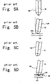
- This ferrule 100 is subjected to the grinding process as shown in Figs. 5A-D. That is, an optical fiber 12 is held in the ferrule 100 having a truncated-cone-like leading end portion defining the leading end face perpendicular to the axis, and then the leading end face is ground to provide a convex spherical surface, refer to Fig. 5A. After the eccentric direction of the core of the optical fiber 12 is inspected, the ferrule 100 is mounted to a jig in such a state that its leading end face is inclined, for instance, at 8° with respect to the surface 120a of the grinding abrasive wheel 120, refer to Fig.
- the leading end face is ground to provide an inclined planar face
- Fig. 5C although the expression of "cut” may be more appropriate, the terminology “grind” is used for convenience.
- the core eccentric direction is set, for instance, so as to be at the front side of this drawing.
- the process advances to a step of grinding the leading end face to provide a convex spherical surface in the similar mounting state to the jig.
- the inclined PC grinding is completed.
- the inclined spherical grinding can be performed similarly to the general convex spherical grinding with the exception of the mounting state in which the ferrule 100 is mounted incliningly, and as shown in Fig.
- this step is referred to as "cutting" when applicable, the end face of the ferrule 100, which is chucked in an inclined state, is depressed onto the surface 120a of the rotating abrasive wheel 120. That is, the ferrule 100 is held and fixed onto a chuck in a state that the axis of the ferrule 100 is inclined at a predetermined angle, for instance, 8°, with respect to the normal of the abrasive wheel surface 120a, and the abrasive wheel 120 is depressed onto the ferrule 100 while being rotated, thereby effecting the inclined planar grinding onto the end face of the ferrule 100.
- a predetermined angle for instance 8°
- the inclined spherical grinding of the prior art is performed such that the end face of the ferrule, which has the cylindrical base portion and tapered, truncated-cone-like leading end portion, is subjected to the general spherical grinding, the inspection of the core eccentricity, and then the inclined planar grinding, and thereafter the inclined planar end portion is ground to provide a spherical surface.
- the above-noted inclined spherical grinding method suffers from a problem in that it requires a larger number of grinding steps in comparison to the general ferrule grinding method. Further, in a case of the inclined spherical grinding, it is preferable to reduce a curvature eccentricity of the leading end spherical surface in comparison to the general ferrule since there arises the adverse effect due to the rotative variation of the ferrule in the connector connecting portion.
- an object of the present invention is to provide a method of grinding a ferrule which can simplify the ferrule grinding steps of the inclined spherical grinding, and reduce the curvature eccentricity.
- a first aspect of the present invention for solving the problem is a method of grinding a ferrule for use in an inclined PC connector which connects inclined ground end faces of optical fibers to each other, characterised in that a perpendicular end face ferrule, having a leading end face perpendicular to an axis, is brought into contact with a grinding sheet placed on an elastic member on a grinding table base with the axis inclined at a predetermined angle, the grinding table base is rotated about a rotation axis while the rotation axis is turned so that the perpendicular end face ferrule is ground to provide an inclined spherical end face.
- a ferrule in the first aspect of the method of grinding a ferrule is characterised in that an optical fiber is preliminarily held on the perpendicular end face ferrule.
- the method of grinding a ferrule is characterized in that an optical fiber is preliminary held on the perpendicular end face ferrule, and a leading end face thereof is ground to provide a spherical surface to effect a core eccentric adjustment.
- the method of grinding a ferrule is characterized by comprising a step of, after the inclined spherical grinding step, holding an optical fiber on the ferrule, and grinding a leading end to finish the same.
- directly grinding a leading end face of a ferrule having a perpendicular end face into an inclined spherical surface provides an effect of suppressing a curvature eccentricity so that it is small.
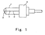
- Fig. 1 is a plan view showing an example of a ferrule which has been ground through a grinding method according to the present invention.
- the ferrule 1, which has been ground through a grinding method according to the present invention is basically similar in configuration to prior art one. That is, it is substantially cylindrical, and has a flange 10 at its rear end portion, and a through-hole 11 at its central portion to which an optical fiber 12 is inserted and fixed by adhesive.
- the leading end portion of the ferrule 1 is formed with a convex spherical inclined surface 13 which is inclined, for instance, at 8° with respect to the surface orthogonal to the axis. This inclined surface 13 is, for instance, about 5-12 mm in radius although it depends on the diameter of the ferrule 1.
- this convex spherical inclined surface 13 is a connection surface by which the optical fiber 12 inserted and fixed onto the ferrule 1 is optically connected to the other mating optical fiber, and as noted above the convex spherical inclined surface 13 preferably has a smaller curvature eccentricity than the general ferrule. Accordingly, in the present embodiment, the curvature eccentricity of the convex spherical inclined surface 13 is suppressed to be smaller by the virtue of the later described grinding method.
- Figs. 2A-B show the grinding steps according to the present embodiment.
- the optical fiber 12 is adhesively held preliminarily on the ferrule 1 having the truncated-cone-like leading end portion defining the leading end face perpendicular to the axis.
- the leading end face of the ferrule 1 in this state is first ground by a grinding machine or the like to provide a convex spherical surface as shown in Fig. 2A, and then the eccentric direction of the core of the optical fiber 12 is inspected.
- This grinding step is similar to the prior art one.
- the ferrule 1 is mounted onto a jig such that the leading end face of the ferrule 1 can be contacted with a planar grinding sheet 22 placed on a grinding table base 20 through an elastic member 21 in an inclined manner, for instance, at 8°.
- the grinding table base 20 is rotated about its axis while the axis is turned so that the leading end face of the ferrule 1 is ground to provide a convex spherical inclined surface.
- the leading end face of the ferrule 1 has been ground to provide the convex spherical surface, that is, the portion contacted with the grinding sheet 22 is spherical, the grinding is carried out along that spherical surface. Therefore, the curvature eccentricity is suppressed.
- the elastic member 21 is elastically deformed and thus the grinding sheet 22 is permitted to be pressed downward to form the leading end face of the ferrule 1 into the convex spherical inclined surface. Therefore, by changing this load, a predetermined convex spherical configuration can be formed.
- the ferrule 1 thus formed by through the above-noted process is then assembled into an optical connector or the like, and connected to another optical connector to provide a reliable optical connection between the optical fibers.
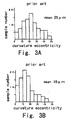
- Figs. 3 are histograms snowing the result.
- Fig. 3A shows the result in the case where the prior art grinding method was employed. It can be found that the variation of the curvature eccentricity of the optical fiber is large and is much distributed to a relatively large-value range of 20-25 ⁇ m.
- Fig. 3B shows the result in the case where the grinding method according to the present invention was employed, and it can be found from this histogram that the variation of the curvature eccentricity is small and the curvature eccentricity is much distributed to a relatively small-value range not more than 20 ⁇ m.
- Figs. 2A and 2B are applied to the ferrule having the truncated-cone-like leading end, these steps may be similarly applied to the ferrule having a cylindrical leading end.
- the leading end face of the ferrule can be ground and processed with high precision, and as can be seen from the graph, the curvature eccentricity can be suppressed so that it is small. Further, according to the grinding method of the present invention, since the step of forming the planar inclined surface can be dispensed with, the number of steps can be reduced to improve the working efficiency.
- the grinding sheet used in the present embodiment is not particularly limited, and for example, it is preferably formed by a diamond sheet having a particle size of 2-18 ⁇ m, a diamond grinding agent, or a combination of these, and the elastic member.
- 8° is given as an example of the inclined angle of the leading end face, but the present invention is not limited to this.
- 9°, 12°, or the like can be selected appropriately depending on the kind of the optical fiber.
- the leading end face of the ferrule having the leading end face perpendicular to the axis is ground to provide the convex spherical surface whose curvature center is on the optical axis, and then the axis is inclined and ground to provide the convex spherical inclined surface, the convex spherical surface which does not have the curvature center on the optical axis.
- the present invention is not limited to this.
- the convex spherical inclined surface may be formed directly from the state in which the leading end face is planar.
- the ferrule since the ferrule is inclined at a predetermined angle with respect to the grinding sheet, a leading portion that is initially contacted with the grinding sheet is substantially in the form of a point, and thus the curvature eccentricity can be suppressed. That is, the end portion of the ferrule in the direction perpendicular to the inclined direction presents a curve and the ferrule and the grinding sheet are contacted with each other through a central portion of this curve. Therefore, the curvature eccentricity can be suppressed similarly as described above.
- the grinding is carried out in a condition in which the optical fiber is preliminarily fixed to the ferrule.
- the present invention is not limited to this.
- the inclined PC ferrule may be formed such that the ferrule is ground to provide the convex spherical inclined surface, and then the optical fiber is inserted and fixed to the ferrule, and thereafter the rear end face is ground.
- the perpendicular end face ferrule having the truncated-cone-like leading end portion tapered relative to the base portion is initially prepared, but the grinding method of the present application may be applied to a ferrule which has a cylindrical leading end portion smaller in diameter than a base portion, i.e. a ferrule having a cylindrical base portion and a cylindrical leading end portion smaller in diameter than the base portion.
- the convex spherical inclined surface is formed without the formation of the planar inclined surface, the curvature eccentricity can be reduced and the variation thereof can be reduced. Further, since the number of cutting step is reduced, the processing time can be shortened and the cost can be also reduced.
Landscapes
- Physics & Mathematics (AREA)
- General Physics & Mathematics (AREA)
- Optics & Photonics (AREA)
- Engineering & Computer Science (AREA)
- Mechanical Engineering (AREA)
- Grinding And Polishing Of Tertiary Curved Surfaces And Surfaces With Complex Shapes (AREA)
- Light Guides In General And Applications Therefor (AREA)
- Mechanical Coupling Of Light Guides (AREA)
Applications Claiming Priority (2)
| Application Number | Priority Date | Filing Date | Title |
|---|---|---|---|
| JP4254498 | 1998-02-24 | ||
| JP10042544A JPH11242135A (ja) | 1998-02-24 | 1998-02-24 | 斜めpcコネクタのフェルール研磨方法 |
Publications (2)
| Publication Number | Publication Date |
|---|---|
| EP0937543A2 true EP0937543A2 (de) | 1999-08-25 |
| EP0937543A3 EP0937543A3 (de) | 2001-05-16 |
Family
ID=12639013
Family Applications (1)
| Application Number | Title | Priority Date | Filing Date |
|---|---|---|---|
| EP99301345A Withdrawn EP0937543A3 (de) | 1998-02-24 | 1999-02-24 | Verfahren zum Schleifen einer Endhülse für schräge PC Steckverbinder |
Country Status (3)
| Country | Link |
|---|---|
| US (1) | US6126519A (de) |
| EP (1) | EP0937543A3 (de) |
| JP (1) | JPH11242135A (de) |
Cited By (1)
| Publication number | Priority date | Publication date | Assignee | Title |
|---|---|---|---|---|
| US11712775B2 (en) | 2017-01-25 | 2023-08-01 | Fives Landis Limited | Machine tools and methods of operation thereof |
Families Citing this family (14)
| Publication number | Priority date | Publication date | Assignee | Title |
|---|---|---|---|---|
| US6712526B1 (en) | 2000-07-13 | 2004-03-30 | Corning Cable Systems Llc | Angled physical contact ferrule and associated method and apparatus for fabricating same |
| JP2002239926A (ja) * | 2001-02-07 | 2002-08-28 | Dainippon Printing Co Ltd | 研磨フィルムおよびその製造方法 |
| USH2141H1 (en) * | 2001-04-06 | 2006-01-03 | Tyco Electronics Corporation | Multifiber ferrule |
| JP2003117793A (ja) * | 2001-10-04 | 2003-04-23 | Seiko Instruments Inc | 端面研磨方法および端面研磨装置 |
| US6918816B2 (en) | 2003-01-31 | 2005-07-19 | Adc Telecommunications, Inc. | Apparatus and method for polishing a fiber optic connector |
| US7209629B2 (en) * | 2004-06-14 | 2007-04-24 | Adc Telecommunications, Inc. | System and method for processing fiber optic connectors |
| US7068906B2 (en) * | 2004-06-14 | 2006-06-27 | Adc Telecommunications, Inc. | Fixture for system for processing fiber optic connectors |
| US7352938B2 (en) * | 2004-06-14 | 2008-04-01 | Adc Telecommunications, Inc. | Drive for system for processing fiber optic connectors |
| CN102289042A (zh) * | 2011-08-19 | 2011-12-21 | 昆山迎翔光电科技有限公司 | 一种sc-apc台阶陶瓷插芯 |
| US9366830B2 (en) * | 2013-02-28 | 2016-06-14 | Lifodas, Uab | Hybrid ferrule and fiber optical test device |
| JP5740800B1 (ja) * | 2014-04-30 | 2015-07-01 | Toto株式会社 | 光レセプタクル |
| JP2021119363A (ja) * | 2018-03-30 | 2021-08-12 | 住友電気工業株式会社 | 光コネクタおよび光接続構造 |
| US12047117B2 (en) | 2020-07-30 | 2024-07-23 | Exfo Inc. | Optical-fiber device for one-cord reference optical power loss measurement |
| US12442719B2 (en) | 2022-01-19 | 2025-10-14 | Exfo Inc. | Duplex optical power loss measurement using an adaptor device |
Citations (3)
| Publication number | Priority date | Publication date | Assignee | Title |
|---|---|---|---|---|
| US5216846A (en) * | 1991-12-17 | 1993-06-08 | Seikoh Giken Co., Ltd. | Method and apparatus for grinding foremost end surface of a ferrule |
| US5464361A (en) * | 1990-06-05 | 1995-11-07 | Seiko Instruments Inc. | Method of making fiber termination |
| US5687269A (en) * | 1994-09-08 | 1997-11-11 | The Whitaker Corporation | Optical connector and polishing method of its end surface |
Family Cites Families (10)
| Publication number | Priority date | Publication date | Assignee | Title |
|---|---|---|---|---|
| JP3116124B2 (ja) * | 1991-08-23 | 2000-12-11 | 東京特殊電線株式会社 | 光ファイバ接続体 |
| JP3544977B2 (ja) * | 1992-10-27 | 2004-07-21 | セイコーインスツルメンツ株式会社 | 端面研磨機 |
| US5351327A (en) * | 1993-06-25 | 1994-09-27 | Minnesota Mining And Manufacturing Company | Polished fiber optic ferrules |
| JP3110228B2 (ja) * | 1993-10-29 | 2000-11-20 | 株式会社精工技研 | 光コネクタフェルール部材、光コネクタフェルール部材の研磨方法、および前記方法で使用するフェルールボディ |
| US5432880A (en) * | 1994-03-17 | 1995-07-11 | At&T Corp. | Angled optical connector ferrule |
| JPH0829639A (ja) * | 1994-07-13 | 1996-02-02 | Seiko Giken:Kk | 光ファイバ端面の球面研磨装置の研磨基盤および光ファイバ端面の球面研磨方法 |
| JP3084471B2 (ja) * | 1994-09-28 | 2000-09-04 | セイコーインスツルメンツ株式会社 | 光コネクタフェルール端面の研磨方法 |
| JP3659671B2 (ja) * | 1994-10-13 | 2005-06-15 | セイコーインスツル株式会社 | 光ファイバ端面研磨機及び研磨方法 |
| WO1996014960A2 (en) * | 1994-11-10 | 1996-05-23 | The Whitaker Corporation | Universal polishing fixture for polishing optical fiber connectors |
| JPH1031130A (ja) * | 1996-07-12 | 1998-02-03 | Seiko Instr Inc | 斜めpc用フェルール及びその研磨方法 |
-
1998
- 1998-02-24 JP JP10042544A patent/JPH11242135A/ja active Pending
-
1999
- 1999-02-23 US US09/256,614 patent/US6126519A/en not_active Expired - Fee Related
- 1999-02-24 EP EP99301345A patent/EP0937543A3/de not_active Withdrawn
Patent Citations (3)
| Publication number | Priority date | Publication date | Assignee | Title |
|---|---|---|---|---|
| US5464361A (en) * | 1990-06-05 | 1995-11-07 | Seiko Instruments Inc. | Method of making fiber termination |
| US5216846A (en) * | 1991-12-17 | 1993-06-08 | Seikoh Giken Co., Ltd. | Method and apparatus for grinding foremost end surface of a ferrule |
| US5687269A (en) * | 1994-09-08 | 1997-11-11 | The Whitaker Corporation | Optical connector and polishing method of its end surface |
Cited By (1)
| Publication number | Priority date | Publication date | Assignee | Title |
|---|---|---|---|---|
| US11712775B2 (en) | 2017-01-25 | 2023-08-01 | Fives Landis Limited | Machine tools and methods of operation thereof |
Also Published As
| Publication number | Publication date |
|---|---|
| JPH11242135A (ja) | 1999-09-07 |
| EP0937543A3 (de) | 2001-05-16 |
| US6126519A (en) | 2000-10-03 |
Similar Documents
| Publication | Publication Date | Title |
|---|---|---|
| US6126519A (en) | Method of grinding ferrule for inclined PC connector | |
| JP3650109B2 (ja) | 光ファイバのフェルールの研磨法 | |
| EP0706853B1 (de) | Vorrichtung und Verfahren zum Polieren der Endfläche einer optischen Fiber | |
| US5464361A (en) | Method of making fiber termination | |
| JP3011869B2 (ja) | 光ファイバコネクタのフェルールの端面の形成方法 | |
| KR100201791B1 (ko) | 공작물에 블록 팁을 형성하는 방법 및 장치 | |
| US20030081909A1 (en) | Ferrule | |
| CA2118087A1 (en) | Planar optical waveguides with low back reflection pigtailing | |
| CN106217233B (zh) | 一种apc短插芯的加工处理方法 | |
| US5909530A (en) | Method for manufacturing ferrule for use with optical fiber connector | |
| US5687269A (en) | Optical connector and polishing method of its end surface | |
| JPH01121805A (ja) | 光コネクタ用組立体およびその研磨治具並びに光ファイバの接続方法 | |
| US6846111B2 (en) | Method of processing optical fiber end portion | |
| JP3062532B2 (ja) | 光ファイバコネクタおよび光ファイバコネクタ用フェルールの製造方法 | |
| JP3267008B2 (ja) | 光コネクタ用フェルールの加工方法 | |
| JP7532975B2 (ja) | 多心コネクタの製造方法及び多心コネクタ | |
| JP3722643B2 (ja) | 光ファイバ固定具の加工方法 | |
| JP2004170563A (ja) | 斜めpcコネクタのフェルール及びその研磨方法 | |
| EP0814354B1 (de) | Lichtwellenleitersteckverbindungen | |
| JP3110228B2 (ja) | 光コネクタフェルール部材、光コネクタフェルール部材の研磨方法、および前記方法で使用するフェルールボディ | |
| JP2000292649A (ja) | 光コネクタ用フェルール及びその端部加工方法 | |
| JP2000338355A (ja) | 光コネクタプラグ、光コネクタ、及び光コネクタプラグの締結方法 | |
| JP2004170564A (ja) | フェルール及びその端面研磨方法 | |
| JPH1031130A (ja) | 斜めpc用フェルール及びその研磨方法 | |
| JPH1158203A (ja) | 光ファイバコネクタの端面研磨方法 |
Legal Events
| Date | Code | Title | Description |
|---|---|---|---|
| PUAI | Public reference made under article 153(3) epc to a published international application that has entered the european phase |
Free format text: ORIGINAL CODE: 0009012 |
|
| AK | Designated contracting states |
Kind code of ref document: A2 Designated state(s): DE GB IT |
|
| AX | Request for extension of the european patent |
Free format text: AL;LT;LV;MK;RO;SI |
|
| PUAL | Search report despatched |
Free format text: ORIGINAL CODE: 0009013 |
|
| AK | Designated contracting states |
Kind code of ref document: A3 Designated state(s): AT BE CH CY DE DK ES FI FR GB GR IE IT LI LU MC NL PT SE |
|
| AX | Request for extension of the european patent |
Free format text: AL;LT;LV;MK;RO;SI |
|
| RIC1 | Information provided on ipc code assigned before grant |
Free format text: 7B 24B 19/22 A, 7B 24B 11/00 B, 7B 24B 13/00 B, 7B 24B 7/16 B |
|
| 17P | Request for examination filed |
Effective date: 20011108 |
|
| AKX | Designation fees paid |
Free format text: DE GB IT |
|
| 17Q | First examination report despatched |
Effective date: 20031001 |
|
| STAA | Information on the status of an ep patent application or granted ep patent |
Free format text: STATUS: THE APPLICATION IS DEEMED TO BE WITHDRAWN |
|
| 18D | Application deemed to be withdrawn |
Effective date: 20050106 |