EP0937614A2 - Verfahren und Vorrichtung zur Steuerung einer Bremsanlage - Google Patents
Verfahren und Vorrichtung zur Steuerung einer Bremsanlage Download PDFInfo
- Publication number
- EP0937614A2 EP0937614A2 EP98119579A EP98119579A EP0937614A2 EP 0937614 A2 EP0937614 A2 EP 0937614A2 EP 98119579 A EP98119579 A EP 98119579A EP 98119579 A EP98119579 A EP 98119579A EP 0937614 A2 EP0937614 A2 EP 0937614A2
- Authority
- EP
- European Patent Office
- Prior art keywords
- signal
- brake
- actuation
- brake pedal
- pedal
- Prior art date
- Legal status (The legal status is an assumption and is not a legal conclusion. Google has not performed a legal analysis and makes no representation as to the accuracy of the status listed.)
- Granted
Links
- 238000000034 method Methods 0.000 title claims abstract description 20
- 238000001514 detection method Methods 0.000 claims description 11
- 230000001276 controlling effect Effects 0.000 claims description 7
- 238000012544 monitoring process Methods 0.000 claims description 4
- 230000001419 dependent effect Effects 0.000 claims description 3
- 230000001105 regulatory effect Effects 0.000 claims description 3
- 230000004913 activation Effects 0.000 abstract 3
- 238000002955 isolation Methods 0.000 description 5
- 230000008569 process Effects 0.000 description 5
- 238000006243 chemical reaction Methods 0.000 description 2
- 238000004590 computer program Methods 0.000 description 2
- 230000002950 deficient Effects 0.000 description 2
- 238000005259 measurement Methods 0.000 description 2
- 230000009467 reduction Effects 0.000 description 2
- 238000000926 separation method Methods 0.000 description 2
- 230000009471 action Effects 0.000 description 1
- 230000006399 behavior Effects 0.000 description 1
- 238000006073 displacement reaction Methods 0.000 description 1
- 230000000694 effects Effects 0.000 description 1
- 239000012530 fluid Substances 0.000 description 1
- 230000006870 function Effects 0.000 description 1
- 230000006872 improvement Effects 0.000 description 1
- 210000003205 muscle Anatomy 0.000 description 1
- 230000007704 transition Effects 0.000 description 1
Images


Classifications
-
- B—PERFORMING OPERATIONS; TRANSPORTING
- B60—VEHICLES IN GENERAL
- B60T—VEHICLE BRAKE CONTROL SYSTEMS OR PARTS THEREOF; BRAKE CONTROL SYSTEMS OR PARTS THEREOF, IN GENERAL; ARRANGEMENT OF BRAKING ELEMENTS ON VEHICLES IN GENERAL; PORTABLE DEVICES FOR PREVENTING UNWANTED MOVEMENT OF VEHICLES; VEHICLE MODIFICATIONS TO FACILITATE COOLING OF BRAKES
- B60T8/00—Arrangements for adjusting wheel-braking force to meet varying vehicular or ground-surface conditions, e.g. limiting or varying distribution of braking force
- B60T8/32—Arrangements for adjusting wheel-braking force to meet varying vehicular or ground-surface conditions, e.g. limiting or varying distribution of braking force responsive to a speed condition, e.g. acceleration or deceleration
- B60T8/88—Arrangements for adjusting wheel-braking force to meet varying vehicular or ground-surface conditions, e.g. limiting or varying distribution of braking force responsive to a speed condition, e.g. acceleration or deceleration with failure responsive means, i.e. means for detecting and indicating faulty operation of the speed responsive control means
- B60T8/92—Arrangements for adjusting wheel-braking force to meet varying vehicular or ground-surface conditions, e.g. limiting or varying distribution of braking force responsive to a speed condition, e.g. acceleration or deceleration with failure responsive means, i.e. means for detecting and indicating faulty operation of the speed responsive control means automatically taking corrective action
- B60T8/94—Arrangements for adjusting wheel-braking force to meet varying vehicular or ground-surface conditions, e.g. limiting or varying distribution of braking force responsive to a speed condition, e.g. acceleration or deceleration with failure responsive means, i.e. means for detecting and indicating faulty operation of the speed responsive control means automatically taking corrective action on a fluid pressure regulator
-
- B—PERFORMING OPERATIONS; TRANSPORTING
- B60—VEHICLES IN GENERAL
- B60T—VEHICLE BRAKE CONTROL SYSTEMS OR PARTS THEREOF; BRAKE CONTROL SYSTEMS OR PARTS THEREOF, IN GENERAL; ARRANGEMENT OF BRAKING ELEMENTS ON VEHICLES IN GENERAL; PORTABLE DEVICES FOR PREVENTING UNWANTED MOVEMENT OF VEHICLES; VEHICLE MODIFICATIONS TO FACILITATE COOLING OF BRAKES
- B60T8/00—Arrangements for adjusting wheel-braking force to meet varying vehicular or ground-surface conditions, e.g. limiting or varying distribution of braking force
- B60T8/32—Arrangements for adjusting wheel-braking force to meet varying vehicular or ground-surface conditions, e.g. limiting or varying distribution of braking force responsive to a speed condition, e.g. acceleration or deceleration
- B60T8/34—Arrangements for adjusting wheel-braking force to meet varying vehicular or ground-surface conditions, e.g. limiting or varying distribution of braking force responsive to a speed condition, e.g. acceleration or deceleration having a fluid pressure regulator responsive to a speed condition
- B60T8/40—Arrangements for adjusting wheel-braking force to meet varying vehicular or ground-surface conditions, e.g. limiting or varying distribution of braking force responsive to a speed condition, e.g. acceleration or deceleration having a fluid pressure regulator responsive to a speed condition comprising an additional fluid circuit including fluid pressurising means for modifying the pressure of the braking fluid, e.g. including wheel driven pumps for detecting a speed condition, or pumps which are controlled by means independent of the braking system
- B60T8/4072—Systems in which a driver input signal is used as a control signal for the additional fluid circuit which is normally used for braking
- B60T8/4081—Systems with stroke simulating devices for driver input
- B60T8/4086—Systems with stroke simulating devices for driver input the stroke simulating device being connected to, or integrated in the driver input device
-
- B—PERFORMING OPERATIONS; TRANSPORTING
- B60—VEHICLES IN GENERAL
- B60T—VEHICLE BRAKE CONTROL SYSTEMS OR PARTS THEREOF; BRAKE CONTROL SYSTEMS OR PARTS THEREOF, IN GENERAL; ARRANGEMENT OF BRAKING ELEMENTS ON VEHICLES IN GENERAL; PORTABLE DEVICES FOR PREVENTING UNWANTED MOVEMENT OF VEHICLES; VEHICLE MODIFICATIONS TO FACILITATE COOLING OF BRAKES
- B60T8/00—Arrangements for adjusting wheel-braking force to meet varying vehicular or ground-surface conditions, e.g. limiting or varying distribution of braking force
- B60T8/32—Arrangements for adjusting wheel-braking force to meet varying vehicular or ground-surface conditions, e.g. limiting or varying distribution of braking force responsive to a speed condition, e.g. acceleration or deceleration
- B60T8/88—Arrangements for adjusting wheel-braking force to meet varying vehicular or ground-surface conditions, e.g. limiting or varying distribution of braking force responsive to a speed condition, e.g. acceleration or deceleration with failure responsive means, i.e. means for detecting and indicating faulty operation of the speed responsive control means
- B60T8/885—Arrangements for adjusting wheel-braking force to meet varying vehicular or ground-surface conditions, e.g. limiting or varying distribution of braking force responsive to a speed condition, e.g. acceleration or deceleration with failure responsive means, i.e. means for detecting and indicating faulty operation of the speed responsive control means using electrical circuitry
-
- B—PERFORMING OPERATIONS; TRANSPORTING
- B60—VEHICLES IN GENERAL
- B60T—VEHICLE BRAKE CONTROL SYSTEMS OR PARTS THEREOF; BRAKE CONTROL SYSTEMS OR PARTS THEREOF, IN GENERAL; ARRANGEMENT OF BRAKING ELEMENTS ON VEHICLES IN GENERAL; PORTABLE DEVICES FOR PREVENTING UNWANTED MOVEMENT OF VEHICLES; VEHICLE MODIFICATIONS TO FACILITATE COOLING OF BRAKES
- B60T2260/00—Interaction of vehicle brake system with other systems
- B60T2260/09—Complex systems; Conjoint control of two or more vehicle active control systems
-
- B—PERFORMING OPERATIONS; TRANSPORTING
- B60—VEHICLES IN GENERAL
- B60T—VEHICLE BRAKE CONTROL SYSTEMS OR PARTS THEREOF; BRAKE CONTROL SYSTEMS OR PARTS THEREOF, IN GENERAL; ARRANGEMENT OF BRAKING ELEMENTS ON VEHICLES IN GENERAL; PORTABLE DEVICES FOR PREVENTING UNWANTED MOVEMENT OF VEHICLES; VEHICLE MODIFICATIONS TO FACILITATE COOLING OF BRAKES
- B60T2270/00—Further aspects of brake control systems not otherwise provided for
- B60T2270/40—Failsafe aspects of brake control systems
- B60T2270/413—Plausibility monitoring, cross check, redundancy
-
- B—PERFORMING OPERATIONS; TRANSPORTING
- B60—VEHICLES IN GENERAL
- B60T—VEHICLE BRAKE CONTROL SYSTEMS OR PARTS THEREOF; BRAKE CONTROL SYSTEMS OR PARTS THEREOF, IN GENERAL; ARRANGEMENT OF BRAKING ELEMENTS ON VEHICLES IN GENERAL; PORTABLE DEVICES FOR PREVENTING UNWANTED MOVEMENT OF VEHICLES; VEHICLE MODIFICATIONS TO FACILITATE COOLING OF BRAKES
- B60T2270/00—Further aspects of brake control systems not otherwise provided for
- B60T2270/82—Brake-by-Wire, EHB
Definitions
- the invention relates to a method and a device to control a brake system according to the generic terms of independent claims.
- Such a method or device is known for example from SAE paper 960991.
- SAE paper 960991 There will described an electro-hydraulic brake system in which from the brake pedal actuation by the driver The driver's braking request is derived. This will, if necessary taking into account other company sizes converted into target brake pressures for the individual wheel brakes.
- the target braking pressures are set for each wheel by pressure control loops based on the specified target pressure and the actual brake pressure measured in the area of the wheel brake.
- the driver braking request is made by at least two Measuring devices determined. Because the one exercised on the wheel brakes Braking force by electrical means depending on that these measuring devices set the desired braking measures to monitor the functionality of these measuring devices and thus measures for checking the correctness of the driver brake request provided.
- suitable, Control measures ensuring the operational safety of the brake system in the event of an error.
- the brake system for the front brakes on hydraulic Actuation is switched.
- the rear brakes continue can be controlled electronically, with operational reliability through an extended plausibility check of the measurement signals representing the actuation Brake pressure signals from the front axle brakes guaranteed is.
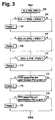
- FIGS. 3 and 4 which is a preferred implementation of error monitoring represent and recognition as a program of a microcomputer.
- FIG. 5 shows the preferred one using a flow chart Realization of an emergency braking operation in the event of a fault.
- Figure 1 shows a preferred embodiment of a electrohydraulic brake system. It shows a master brake cylinder HBZ with storage container 10 to which one from Driver operated brake pedal is attached. Further is a hydraulic unit 14 is provided, which valve and Pump arrangements for controlling the wheel brakes 16, 18, 20 and contains 22. With the brake pedal 12 is a brake pedal switch 24 connected, which when the brake pedal is pressed closes, and a measuring device 26 for detecting the deflection of the brake pedal.
- the brake pedal switch can be used as simple closer can be designed or for improvement the ability to be monitored as a double switch with an NC contact and a closer. Likewise, the measuring device 26 for Detection of the deflection of the pedal can be designed redundantly.
- a pedal travel simulator PWS is also provided, which a familiar experience for the driver when the brake pedal is pressed Pedal feeling regarding counterforce and pedal deflection simulated.
- MV_TVR and MV_TVL inserted, which closed by energization in the case of an electrically controlled brake system becomes.
- a pressure sensor 28 from the driver via the Brake pedal actuation applied pressure.
- the main brake cylinder is hydraulically separated from the isolating valves Pressure control system disconnected.
- Pressure control system In the pressure control system are for each wheel brake has a pressure modulator for brake pressure control contain.
- a pressure modulator consists of one Inlet valve (MV_UVR, MV_UVL, MV_UHR, MV_UHL), one outlet valve each (MV_DVR, MV_DVL, MV_DHR, MV_DHL) and one each Pressure sensor 30, 32, 34 and 36, which the pressure in the wheel brake leading management measures.
- MV_UVR, MV_UVL, MV_UHR, MV_UHL Inlet valve
- MV_DVR MV_DVL
- MV_DHR MV_DHR
- MV_DHL Pressure sensor 30, 32, 34 and 36
- relief valves are MV_EVA and MV_EHA for everyone Axis provided, the pressure reduction in the de-energized state allow from the wheel pressure modulators of an axle. You connect the pressure modulators of an axis with those to the reservoir 10 leading return lines. In the electrically controlled Operating status, these two valves are permanent energized, i.e. closed. There is also a temperature compensation valve MV_TKVL and MV_TKVR for everyone Front wheel pressure modulator provided. These valves are deenergized are closed and are released from the pressure modulator for pressure reduction of a front wheel opened by energization when certain conditions, especially a very long one Braking time. The temperature compensation valves connect the brake line to the wheel brake with the return line.
- the energy for brake pressure modulation comes from a single-piston high-pressure pump driven by an electric motor 42. This is at a high pressure accumulator 44 connected, which serves as an intermediate buffer and its pressure is detected by a pressure sensor 46.
- the pressure line of the Pump 42 leads to the inlet valves of the wheel brakes while the suction line of the pump 42 connected to the reservoir 10 is.
- the invention described below How-to, however, is not only related advantageously used with such a hydraulic circuit, but wherever in connection with a electrically controlled braking system the driver's braking request is detected via measuring devices, errors in the area recognized this brake request detection and countered these errors must become.
- the brake system described in FIG. 1 operates in normal operation as follows.
- the driver steps on the brake pedal. He senses a path-dependent counterforce. This path dependency is defined by the characteristic of the pedal travel simulator educated.
- the brake pedal switch and / or the The isolating valves (MV_TVR and MV_TVL) and the relief valves (MV_EVA and MV_EHA) closed.
- the Master brake cylinder HBZ builds up a pressure that from the Pedal force results. From the signals of the brake light switch 24, the displacement sensor 26 and / or the pressure sensor 28 the driver's braking request, for example, as a target deceleration or calculated as the target braking force.
- the individual target wheel brake pressures are formed. Each these pressures depend on the driving condition and slip condition modified and via the wheel pressure modulators through valve energization adjusted. Be in a closed loop the current pressures on the wheel pressure sensors for each wheel brake used for the target-actual comparison. With different Target pressures in the left and right wheel one The equalization valves are closed in each axis Wheel brake the predetermined target pressure by controlling the intake and exhaust valves in the sense of regulating the actual brake pressure adjusted to the target brake pressure. To build up pressure on a wheel brake, the inlet valve is energized so far, that the desired target pressure in the wheel brake with the desired dynamics. A decrease in pressure is achieved accordingly by energizing the exhaust valve, taking brake fluid over to the reservoir the return line flows back.
- the relief valves come into effect in the event of a fault in the system. If during if the braking system fails, all fall Valves return to their de-energized state. The relief valves then open the pressure modulators to the return line, so that no brake pressure can be locked up. These valves also allow volume compensation in the idle state to the container in case of temperature fluctuations.
- the electrically operated valves and the pump 42 are controlled by at least one electronic control unit, which is outlined in Figure 2. It includes at least a microcomputer 102, an input circuit 104, an output circuit 106 and a connecting these elements Bus system 108 for mutual data exchange.
- Input circuit 104 is lines 50 and 54 of FIG Brake pedal switch 24 and pedal travel sensor 26 supplied. Further input lines 118 through 124 connect the input circuit 104 with the sensors assigned to each wheel brake 30 to 36.
- An input line 140 is also provided, that of the measuring device 46 for detecting the storage pressure is fed to the input line 104.
- Other input lines 126 to 128 connect the input circuit 104 with measuring devices 130 to 132 for detecting further Operating parameters of the brake system, the vehicle and / or its Drive unit.
- Such operating sizes are, for example the wheel speeds, possibly that of the engine torque, axle loads, the Pressure in the brake line (sensor 28), etc.
- To the output circuit 106 several output lines are connected. The output lines are shown by way of example which the valves of the pressure modulators are operated.
- the pump 42 is controlled via a further output line 138.
- the control unit 100 controls the brake system depending on of the supplied signal quantities in the above Senses.
- the Brake pedal actuation a brake pedal switch signal BLS, on from the master cylinder by operating the brake pedal controlled brake pressure PHZ and the brake pedal travel Signal indicating SPED available. These signals are linked to each other for error detection.
- the preferred The exemplary embodiment is based on the flow chart in FIG. 3 shown. The program outlined there runs during and outside of a braking process at predetermined time intervals from.
- the available actuation variables read.
- This limit value for the pedal value is preferred Exemplary embodiment on a pedal travel placed in front of 1.5 mm. If both of these conditions are met, a flag "Error1" is set in accordance with step 104. Is a the conditions are not met, so can be from a faultless Operation can be assumed. If necessary, in one embodiment, the possibly set mark (Step 104) reset. After that, in step 106 the condition checks whether the brake pedal switch signal has the value zero, i.e.
- a second predetermined Limit SPED1 is.
- This limit is preferred Exemplary embodiment 20 mm. Are these both conditions are met, a mark is made according to step 108 "Error2" set. If one of the conditions is not met, as in step 108 with query step 110 continued. If necessary, with a no answer reset the set mark.
- query step 110 checks whether the brake pedal switch signal is zero, i.e. no actuation, displays while the master cylinder brake pressure PHZ exceeds a predetermined limit value PHZ0. In the preferred embodiment, this limit is selected to 5 bar.
- step 112 If these conditions are met, set the mark "Error 3" in accordance with step 112, otherwise, possibly resetting the mark, with step 114 continued.
- step 114 There are the pedal travel and pressure signals compared with each other. It shows that the pedal travel is opposite the corresponding pressure value is too small, i.e. For the pedal travel displayed is too high a pressure or for indicated pressure a too small pedal travel is measured, the flag "Fehler4" is set according to step 116. Lie the two values to each other with a view to that in step 114 checked relation correctly, if necessary under Reset the mark as after step 116 in step 118 checks whether the pedal travel signal compared to the corresponding Pressure signal is too large.
- Step 120 the pressure value compared to a reference value is small or that for a given pressure signal value the measured Pedal travel is too large compared to a reference value. Is if this is the case, the "Error 5" flag is set in step 120 and ended the program. With a no answer in Step 118 becomes the program, optionally under reset the brand, also ended.
- the program shown in Figure 4 is also given Time outside and during a braking process run through with and without emergency operation so that the error separation is also possible during emergency braking.
- this is dispensed with and only run through the program when there is an emergency braking operation is initiated, which has no transition from the electrical controlled braking for purely hydraulically controlled Braking includes at least one wheel brake.
- step 150 it is checked whether the mark "Fehler1" is set. If this is not the case, step 152 checks whether the flag "Fehler2" is set. Is this Mark is not set, it is checked in step 154 whether the "Error3" mark is set. If this is not the case, the mark "Fehler4" is checked in step 156. It is too if this is not set, the error flag becomes step 158 5 queried. If this is also not set, then according to Step 160 assumed normal operation of the brake system and the electronic control of the brake depending on Driver brake request carried out. After step 160, this becomes program ended and run through to the next point in time.
- step 150 If step 150 has shown that the error flag 1 is set, it is checked in step 162 whether the error flag 4 is set is. If this is the case, then according to step 164 Conclusion that the pedal travel sensor one too indicates small path. This is because when the pedal is pressed the pedal travel is too small and at the same time given Pressure signal value the pedal travel is also too small. This Error information is displayed and / or saved. It is also switched to an emergency braking mode (back-up), in which all valves are de-energized and thus the Isolation valves MV_TVR and MV_TVL are opened. The driver The front axle then brakes using the hydraulic system it creates Connection from the master brake cylinder to the wheel brakes.
- back-up emergency braking mode
- the rear axle continue to be electrically controlled by the pressure set point either based on a braking request the pressure signal or a combination of pressure and pedal travel signal is formed.
- a preferred embodiment of this Electrical emergency operation is based on the flow chart shown in Figure 5.
- the Error mark 4 is not set, is also carried out according to step 166 the emergency braking operation described above is initiated. As Error information is displayed or saved that either the pedal travel sensor is faulty because it has a delivers too small a value or the brake pedal switch without pedal actuation indicates pedal actuation.
- step 164 or 166 the program is ended.
- step 152 If step 152 has shown that the error flag 2 is set, it is checked in step 168 whether the error flag 3 is also set is. If this is the case, emergency braking will also be activated initiated and according to step 170 as an error state a defective brake pedal switch specified, displayed or stored, which shows the value zero despite pedaling. If the error mark 3 is not set, the step 172 checks whether the error flag 5 is set. Is this if this is the case, emergency braking operation is initiated in accordance with step 174 and too large a value of the brake pedal travel as a fault pattern determined, displayed or saved.
- step 176 emergency braking operation initiated and as a fault pattern either assumed that the pedal travel signal is too large or from a defective brake pedal switch, which despite operation displays the value zero. This error information is also displayed and / or saved.
- step 178 a check is made as to whether whether the error flag 4 is also set (step 178). If this is the case, emergency braking operation is carried out in accordance with step 180 initiated and the value of the Pressure sensor isolated. If the error mark 4 is not set, emergency braking operation is also initiated in step 182 and too high a pressure value as a fault pattern or a Brake pedal switch showing zero despite operation accepted. After step 180 or 182, the program completed.
- Step 184 is a wheel pressure actual value PRADIST of a front wheel brake as well as the associated brake pressure setpoint PRADSOLL. It is then checked in step 186 whether the target value stationary is greater than the actual value. Is this the If this is the case, emergency braking operation is initiated in accordance with step 188 and assumed a hard pedal as a fault pattern. This hard The cause of the pedal is that a separating valve is faulty is open. Steps 184 and 186 are used for go through each front wheel separately.
- step 186 did step 186 result in that the setpoint is not greater in stationary operation than the actual pressure value is, according to step 190 also switched to emergency braking mode and a hard error Pedal, pedal travel too small or pressure too large accepted. The hard pedal may then become the cause therefore, that the pedal travel simulator or Floating circle piston stuck in the master cylinder. After the steps 188 and 190 the program is ended.
- step 158 If step 158 has shown that the error flag 5 is set, so an emergency operation is initiated in step 192 in which not the hydraulic connection between the brake pedal and the wheel brakes is unlocked, but in which the wheel pressure setpoints PRADSOLL is formed on the basis of the pedal travel signal SPED becomes. It is stated as an error pattern that either the pedal travel is measured too large, the pressure value is too small, air the spring of the pedal travel simulator is broken in the brake circuit or there is a leak in the hydraulic circuit. After step 192, the program is ended.
- Step 192 an electrical Emergency operation is initiated. In this case the Monitoring shown in Figure 4 continues to be performed.
- FIG. 5 A preferred embodiment for the electrical Emergency operation (back-up) is shown in FIG. 5. Also this is a flow chart which is the preferred one Realization of the procedure outlined as a computer program.
- step 200 the isolation valves MV_TVR and MV_TVL in their de-energized state switched, i.e. open.
- Step 202 the brake request signals pedal travel and master cylinder pressure read.
- the braking force on the front brakes is through muscle power via the now open hydraulic Connection from the master cylinder to the wheel brakes built up.
- step 206 it is checked in step 206 whether the braking request formed from the actuation signals (solely from the path signal or the pressure signal or a combination of the two signals) with the detected Brake pressures in the front axle brakes are plausible.
- step 208 the setpoint is then for the rear axle brakes based on the braking request determines and according to step 210 a control of the wheel brake pressure depending on the setpoint and the measured actual values carried out. After that, the program goes to step 202 repeated.
- step 206 braking request and front axle brake pressure not plausible to each other, is a difficult one Error before, so that according to step 212 on the rear axle control is dispensed with and that shown in FIG. 5 Program part has ended.
- this emergency braking operation then carried out when a sensor for detecting the driver's brake request fails. This is the case in step 164, 174 and 180. The braking request is then not considered to be faulty recognized actuation signal formed.
- This type of emergency braking operation is used in the exemplary embodiment carried out all error states, whereby if not clear A combination of pedal travel and Pressure, preferably the larger of the two values, for determination of the setpoint is used.
- the determined fault patterns are displayed or in a Fault memory stored according to a specified fault code.
- a predetermined filter time expires, after which it is only possible to determine another error.
Landscapes
- Engineering & Computer Science (AREA)
- Physics & Mathematics (AREA)
- Fluid Mechanics (AREA)
- Transportation (AREA)
- Mechanical Engineering (AREA)
- Regulating Braking Force (AREA)
- Valves And Accessory Devices For Braking Systems (AREA)
Abstract
Description
Claims (11)
- Verfahren zur Steuerung einer Bremsanlage eines Kraftfahrzeugs, bei welchem ein erstes die Auslenkung bei Betätigung eines Bremspedals repräsentierendes Signal erfaßt wird, bei welchem ein zweites zu den ersten Signal redundanten Signal erfaßt wird, bei welchem ein drittes die Betätigung des Bremspedals anzeigendes binäres Signal erfaßt wird, wobei zur Fehlerüberwachung diese drei Signale miteinander verglichen werden, dadurch gekennzeichnet, daß ein zu kleines Auslenkungssignal angenommen wird, wenn bei einem die Betätigung des Pedals anzeigenden binären Signal das Auslenkungssignal gegenüber dem zweiten Signal zu klein ist, und daß ein zu großes Signal angenommen wird, wenn bei eine Nichtbetätigung des Pedals anzeigendem Schalterzustand, einem zu großen ersten Signal und einem zu großen zweiten Signal das erste Signal gegenüber dem zweiten Signal zu groß ist.
- Verfahren nach Anspruch 1, dadurch gekennzeichnet, daß das zweite Signal einen Hauptzylinderdruck, der von der Bremspedalbetätigung beeinflußt wird oder eine Betätigungskraft, darstellt, während das dritte Signal das Signal eines Bremspedalschalters ist.
- Verfahren nach einem der vorhergehenden Ansprüche, dadurch gekennzeichnet, daß die Bremsanlage eine elektrisch steuerbare Bremsanlage ist, bei der Druck in den Radbremsen gemessen wird und ein Solldruck für die Radbremsen abhängig vom Fahrerbremswunsch gebildet wird, wobei bei einer Unplausibilität zwischen dem ersten und dem zweiten Signal und bei einem zu großem Solldruckwert gegenüber einem Istdruckwert ein zu hartes Pedal erkannt wird.
- Verfahren zur Steuerung der Bremsanlage eines Kraftfahrzeugs, wobei die Betätigung des Bremspedals durch wenigstens zwei Signale erfaßt wird, wobei abhängig von wenigstens einem Betätigungssignale Sollwerte für die an den Radbremsen aufzubauenden Bremsdrücke ermittelt wird und diese eingeregelt wird, wobei Fehler im Bereich Erfassung der Betätigung des Bremspedals ermittelt werden, dadurch gekennzeichnet, daß bei einem Fehler im Bereich Erfassung der Betätigung des Bremspedals die Radbremsdrücke an den Vorderachsbremsen durch die Bremspedalbetätigung auf hydraulischem Wege aufgebracht werden.
- Verfahren nach Anspruch 4, dadurch gekennzeichnet, daß die Bremsdrücke an den Hinterachsbremsen bei einem Fehler weiterhin elektrisch auf der Basis von Soll- und Istbremsdrücken geregelt werden.
- Verfahren nach Anspruch 4 oder 5, dadurch gekennzeichnet, daß dies bei erkanntem Ausfall einer Meßeinrichtung erfolgt.
- Verfahren nach Anspruch 4, 5 oder 6, dadurch gekennzeichnet, daß im Fehlerfall eine Plausibilitätsüberprüfung zwischen den Bremsdrücken der Vorderachsbremsen und dem wenigstens einen die Betätigung des Bremspedals erfassenden Signal erfolgt.
- Verfahren nach Anspruch 7, dadurch gekennzeichnet, daß bei vorhandener Plausibilität die Hinterachsbremsen geregelt, bei nicht vorhandener Plausibilität die Hinterachsbremsen abgeschaltet sind.
- Verfahren nach einem der vorhergehenden Ansprüche, dadurch gekennzeichnet, daß die erkannten Fehler als Fehlerinformationen codiert in einem Speicher abgelegt werden.
- Vorrichtung zur Steuerung der Bremsanlage eines Fahrzeugs, mit einer elektronischen Steuereinheit, die ein erstes die Auslenkung bei Betätigung eines Bremspedals repräsentierendes Signal, die ein zweites zu den ersten Signal redundanten Signal und die ein drittes die Betätigung des Bremspedals anzeigendes binäres Signal erfaßt, die zur Fehlerüberwachung diese drei Signale miteinander vergleicht, dadurch gekennzeichnet, daß die Steuereinheit ein zu kleines Auslenkungssignal anzeigt, wenn bei einem die Betätigung des Pedals anzeigenden binären Signal das Auslenkungssignal gegenüber dem zweiten Signal zu klein ist, und daß sie ein zu großes Signal anzeigt, wenn bei einem Nichtbetätigung des Pedals anzeigendem Schalterzustand, einem zu großen ersten Signal und einem zu großen zweiten Signal das erste Signal gegenüber dem zweiten Signal zu groß ist.
- Vorrichtung zur Steuerung der Bremsanlage eines Kraftfahrzeugs, mit einer elektronischen Steuereinheit, die die Betätigung des Bremspedals durch wenigstens ein Signal erfaßt, die abhängig von diesem wenigstens einen Betätigungssignal Sollwerte für die an den Radbremsen aufzubauenden Bremsdrücke ermittelt und diese eingeregelt, die ferner Fehler im Bereich Erfassung der Betätigung des Bremspedals ermittelt, dadurch gekennzeichnet, daß die Steuereinheit bei einem Fehler im Bereich Erfassung der Betätigung des Bremspedals die hydraulischen Verbindung zwischen dem Bremspedal und den Radbremsen freischaltet, so daß die Radbremsdrücke durch die Bremspedalbetätigung auf hydraulischem Wege aufgebracht werden.
Applications Claiming Priority (2)
| Application Number | Priority Date | Filing Date | Title |
|---|---|---|---|
| DE19811265 | 1998-02-21 | ||
| DE1998111265 DE19811265B4 (de) | 1998-02-21 | 1998-02-21 | Verfahren und Vorrichtung zur Steuerung einer Bremsanlage |
Publications (3)
| Publication Number | Publication Date |
|---|---|
| EP0937614A2 true EP0937614A2 (de) | 1999-08-25 |
| EP0937614A3 EP0937614A3 (de) | 2000-10-11 |
| EP0937614B1 EP0937614B1 (de) | 2008-10-15 |
Family
ID=7861003
Family Applications (1)
| Application Number | Title | Priority Date | Filing Date |
|---|---|---|---|
| EP19980119579 Expired - Lifetime EP0937614B1 (de) | 1998-02-21 | 1998-10-16 | Verfahren und Vorrichtung zur Steuerung einer Bremsanlage |
Country Status (3)
| Country | Link |
|---|---|
| EP (1) | EP0937614B1 (de) |
| JP (1) | JPH11348752A (de) |
| DE (2) | DE19811265B4 (de) |
Cited By (8)
| Publication number | Priority date | Publication date | Assignee | Title |
|---|---|---|---|---|
| WO2001014195A1 (de) * | 1999-08-25 | 2001-03-01 | Continental Teves Ag & Co. Ohg | Verfahren und vorrichtung zur ermittlung einer konsolidierten eingangsgrösse |
| WO2002032736A1 (en) * | 2000-10-14 | 2002-04-25 | Trw Limited | Rear-axle demand for use with front push-through in electrohydraulic (ehb) braking systems |
| WO2002038427A1 (de) * | 2000-11-10 | 2002-05-16 | Continental Teves Ag & Co. Ohg | Vorrichtung zur von elektromagnetisch betätigbaren ventilen in einer elektrohydraulichen bremsanlage |
| WO2002051679A1 (de) * | 2000-12-23 | 2002-07-04 | Robert Bosch Gmbh | Verfahren und vorrichtung zum erzeugen eines bremssignals |
| FR2821598A1 (fr) * | 2000-12-30 | 2002-09-06 | Bosch Gmbh Robert | Dispositif et procede pour surveiller un capteur de pression notamment d'une installation de freinage de vehicule automobile |
| EP1308377A1 (de) * | 2001-10-30 | 2003-05-07 | Kässbohrer Geländefahrzeug AG | Kettenfahrzeug |
| CN101746363A (zh) * | 2008-12-09 | 2010-06-23 | 赵继安 | 智能监控车距及报警自动刹车装置 |
| WO2012136293A1 (de) * | 2011-04-05 | 2012-10-11 | Lucas Automotive Gmbh | Technik zum redundanten erfassen einer betätigung einer kraftfahrzeug-bremsanlage |
Families Citing this family (6)
| Publication number | Priority date | Publication date | Assignee | Title |
|---|---|---|---|---|
| DE10036286B4 (de) * | 2000-07-26 | 2009-07-30 | Robert Bosch Gmbh | Hydraulische Fahrzeugbremsanlage |
| DE102007035326B4 (de) * | 2007-07-27 | 2026-03-26 | Robert Bosch Gmbh | Sensorkonzept für eine elektrisch betätigte Bremse |
| JP5168038B2 (ja) * | 2008-09-12 | 2013-03-21 | トヨタ自動車株式会社 | ブレーキ制御装置 |
| JP5672955B2 (ja) * | 2010-10-26 | 2015-02-18 | 日産自動車株式会社 | ブレーキの診断装置 |
| KR102148320B1 (ko) * | 2014-05-30 | 2020-08-26 | 주식회사 만도 | 차량의 능동 유압 부스터 시스템 및 그 제어방법 |
| DE102016221584B4 (de) | 2016-11-03 | 2019-09-05 | Audi Ag | Verfahren zur Steuerung einer Bremsanlage eines Kraftfahrzeugs |
Citations (1)
| Publication number | Priority date | Publication date | Assignee | Title |
|---|---|---|---|---|
| DE19510522A1 (de) | 1995-03-23 | 1996-09-26 | Bosch Gmbh Robert | Verfahren und Vorrichtung zur Steuerung bzw. Regelung der Bremsanlage eines Fahrzeugs |
Family Cites Families (19)
| Publication number | Priority date | Publication date | Assignee | Title |
|---|---|---|---|---|
| JPS63270273A (ja) * | 1987-04-28 | 1988-11-08 | Mazda Motor Corp | 車載用電子制御装置の故障コ−ドメモリ消去方法 |
| JP2662588B2 (ja) * | 1988-01-28 | 1997-10-15 | 住友電気工業株式会社 | 車載用電子制御装置の故障コードメモリ消去方法 |
| JP2693172B2 (ja) * | 1988-04-20 | 1997-12-24 | 富士通テン株式会社 | 自動車用故障判定装置を用いるアンチスキッド制御装置 |
| DE3829949A1 (de) * | 1988-09-03 | 1990-03-15 | Daimler Benz Ag | Verfahren zum betrieb einer elektrischen druckmittel-betriebsbremseinrichtung und steuervorrichtung zur durchfuehrung des verfahrens |
| JP2864744B2 (ja) * | 1990-12-20 | 1999-03-08 | トヨタ自動車株式会社 | ブレーキ操作量センサのフェール検出装置 |
| JPH04232154A (ja) * | 1990-12-28 | 1992-08-20 | Toyota Motor Corp | ブレーキ装置のセンサフェール検出方法 |
| JPH04243658A (ja) * | 1991-01-23 | 1992-08-31 | Toyota Motor Corp | 電気制御式ブレーキ装置のフェール検出方法 |
| WO1993000236A1 (en) * | 1991-06-26 | 1993-01-07 | Allied-Signal Inc. | Electrohydraulic braking system with push through capability |
| JPH05184007A (ja) * | 1992-01-06 | 1993-07-23 | Honda Motor Co Ltd | 電動車両の制動装置 |
| JP3336633B2 (ja) * | 1992-07-30 | 2002-10-21 | 住友電気工業株式会社 | 電子制御ブレーキ装置および該ブレーキ装置におけるブレーキ特性設定方法 |
| US5246283A (en) * | 1992-09-08 | 1993-09-21 | General Motors Corporation | Electro-hydraulic brake apply system |
| JP3261226B2 (ja) * | 1993-09-16 | 2002-02-25 | 本田技研工業株式会社 | 車両のブレーキ装置 |
| DE4339570B4 (de) * | 1993-11-19 | 2004-03-04 | Robert Bosch Gmbh | Elektronisches Bremssystem |
| DE4343314A1 (de) * | 1993-12-18 | 1995-06-22 | Bosch Gmbh Robert | Fremdkraftbremsanlage |
| DE19510525A1 (de) * | 1995-03-23 | 1996-09-26 | Bosch Gmbh Robert | Verfahren und Vorrichtung zur Steuerung bzw. Regelung der Bremsanlage eines Fahrzeugs |
| DE19548248A1 (de) * | 1995-12-22 | 1997-06-26 | Bosch Gmbh Robert | Verfahren und Vorrichtung zur Steuerung einer Pumpe eines elektrohydraulischen Bremssystems |
| JP3521634B2 (ja) * | 1996-08-01 | 2004-04-19 | トヨタ自動車株式会社 | ブレーキ液圧制御装置 |
| JPH10217936A (ja) * | 1997-02-10 | 1998-08-18 | Tokico Ltd | 車両用ブレーキ制御装置 |
| JP4096378B2 (ja) * | 1997-07-17 | 2008-06-04 | 株式会社デンソー | ブレーキ装置 |
-
1998
- 1998-02-21 DE DE1998111265 patent/DE19811265B4/de not_active Expired - Lifetime
- 1998-10-16 EP EP19980119579 patent/EP0937614B1/de not_active Expired - Lifetime
- 1998-10-16 DE DE59814303T patent/DE59814303D1/de not_active Expired - Lifetime
-
1999
- 1999-02-19 JP JP11041556A patent/JPH11348752A/ja active Pending
Patent Citations (1)
| Publication number | Priority date | Publication date | Assignee | Title |
|---|---|---|---|---|
| DE19510522A1 (de) | 1995-03-23 | 1996-09-26 | Bosch Gmbh Robert | Verfahren und Vorrichtung zur Steuerung bzw. Regelung der Bremsanlage eines Fahrzeugs |
Non-Patent Citations (1)
| Title |
|---|
| SAE-PAPER 960991 |
Cited By (16)
| Publication number | Priority date | Publication date | Assignee | Title |
|---|---|---|---|---|
| WO2001014195A1 (de) * | 1999-08-25 | 2001-03-01 | Continental Teves Ag & Co. Ohg | Verfahren und vorrichtung zur ermittlung einer konsolidierten eingangsgrösse |
| GB2367869B (en) * | 2000-10-14 | 2004-10-06 | Trw Ltd | Rear-axle demand for use with front push-through in electrohydraulic (EHB) braking systems |
| WO2002032736A1 (en) * | 2000-10-14 | 2002-04-25 | Trw Limited | Rear-axle demand for use with front push-through in electrohydraulic (ehb) braking systems |
| US6824228B2 (en) | 2000-10-14 | 2004-11-30 | Trw Limited | Rear-axle demand for use with front push-through in electrohydraulic (EHB) braking systems |
| WO2002038427A1 (de) * | 2000-11-10 | 2002-05-16 | Continental Teves Ag & Co. Ohg | Vorrichtung zur von elektromagnetisch betätigbaren ventilen in einer elektrohydraulichen bremsanlage |
| US6871917B2 (en) | 2000-11-10 | 2005-03-29 | Continental Teves Ag & Co. Ohg | Device for controlling electromagnetically operated valves |
| WO2002051679A1 (de) * | 2000-12-23 | 2002-07-04 | Robert Bosch Gmbh | Verfahren und vorrichtung zum erzeugen eines bremssignals |
| DE10065012B4 (de) * | 2000-12-23 | 2014-08-07 | Robert Bosch Gmbh | Verfahren und Vorrichtung zum Erzeugen eines Bremssignals |
| FR2821598A1 (fr) * | 2000-12-30 | 2002-09-06 | Bosch Gmbh Robert | Dispositif et procede pour surveiller un capteur de pression notamment d'une installation de freinage de vehicule automobile |
| US6678593B2 (en) | 2000-12-30 | 2004-01-13 | Robert Bosch Gmbh | Device and method for monitoring a pressure sensor |
| US6782960B2 (en) | 2001-10-30 | 2004-08-31 | Kaessbohrer Geländefahrzeug AG | Tracked vehicle |
| EP1308377A1 (de) * | 2001-10-30 | 2003-05-07 | Kässbohrer Geländefahrzeug AG | Kettenfahrzeug |
| CN101746363A (zh) * | 2008-12-09 | 2010-06-23 | 赵继安 | 智能监控车距及报警自动刹车装置 |
| CN101746363B (zh) * | 2008-12-09 | 2014-01-29 | 赵继安 | 智能监控车距及报警自动刹车装置 |
| WO2012136293A1 (de) * | 2011-04-05 | 2012-10-11 | Lucas Automotive Gmbh | Technik zum redundanten erfassen einer betätigung einer kraftfahrzeug-bremsanlage |
| US11292446B2 (en) | 2011-04-05 | 2022-04-05 | Zf Active Safety Gmbh | Technique for redundant registration of an actuation of a motor-vehicle braking system |
Also Published As
| Publication number | Publication date |
|---|---|
| DE59814303D1 (de) | 2008-11-27 |
| DE19811265A1 (de) | 1999-08-26 |
| DE19811265B4 (de) | 2006-09-21 |
| JPH11348752A (ja) | 1999-12-21 |
| EP0937614A3 (de) | 2000-10-11 |
| EP0937614B1 (de) | 2008-10-15 |
Similar Documents
| Publication | Publication Date | Title |
|---|---|---|
| EP0937618B1 (de) | Verfahren und Vorrichtung zur Überprüfung einer Bremsanlage | |
| EP0937617B1 (de) | Verfahren und Vorrichtung zur Steuerung einer Bremsanlage | |
| EP0937620B1 (de) | Verfahren und Vorrichtung zur Steuerung einer Bremsanlage | |
| EP0937621B1 (de) | Verfahren und Vorrichtung zur Steuerung einer Bremsanlage | |
| DE10036287B4 (de) | Verfahren und Vorrichtung zur Steuerung von Radbremsen | |
| DE60003310T2 (de) | Aushilfs-/back-up-bremssystem in einem elektrohydraulischen bremssystem | |
| DE19603863B4 (de) | Verfahren und Vorrichtungen zur Überprüfung der Bremsanlage eines Fahrzeugs | |
| EP0979189B1 (de) | Schaltungsanordnung für ein kraftfahrzeug-regelungssystem | |
| EP2627546B1 (de) | Verfahren zur überwachung einer bremsanlage sowie bremsanlage | |
| DE112020000597T5 (de) | Bremssystem | |
| DE19811265B4 (de) | Verfahren und Vorrichtung zur Steuerung einer Bremsanlage | |
| EP0734929B1 (de) | Elektrohydraulische Bremsanlage | |
| DE69509909T2 (de) | Hydraulische fahrzeugbremsanlagen | |
| DE19831541A1 (de) | Bremsbetätigungsverfahren, Bremsensteuerung, Bremsanlage und Kraftfahrzeuge mit einer solchen Bremsanlage | |
| WO2002042138A1 (de) | Verfahren zur steuerung einer elektrohydraulischen bremsanlage | |
| DE102022206558A1 (de) | Vorrichtung und ein Verfahren zur redundanten Steuerung eines hydraulischen Bremssystems | |
| DE19729097B4 (de) | Verfahren und Vorrichtung zur Steuerung einer Bremsanlage | |
| DE19706850B4 (de) | Verfahren und Vorrichtung zur Steuerung einer Bremsanlage eines Fahrzeugs | |
| DE69833404T2 (de) | Manuelle Hinterbremssteuerung für eine elektro-hydraulische Bremsanlage | |
| DE3828931A1 (de) | Verfahren zur ueberwachung der funktion einer bremsanlage | |
| DE69616869T2 (de) | Elektronische Bremssysteme | |
| DE102019204904B3 (de) | Bremskrafterzeuger und Betriebsverfahren | |
| DE102023208177B4 (de) | Rückfallebene mit weichem Pedal | |
| EP1144233B1 (de) | Bremsanlage mit hydraulischer bremskraftverstärkung und verfahren hierzu | |
| DE102024208790A1 (de) | Überwachung eines redundanten Bremssystems |
Legal Events
| Date | Code | Title | Description |
|---|---|---|---|
| PUAI | Public reference made under article 153(3) epc to a published international application that has entered the european phase |
Free format text: ORIGINAL CODE: 0009012 |
|
| AK | Designated contracting states |
Kind code of ref document: A2 Designated state(s): DE FR GB |
|
| AX | Request for extension of the european patent |
Free format text: AL;LT;LV;MK;RO;SI |
|
| PUAL | Search report despatched |
Free format text: ORIGINAL CODE: 0009013 |
|
| AK | Designated contracting states |
Kind code of ref document: A3 Designated state(s): AT BE CH CY DE DK ES FI FR GB GR IE IT LI LU MC NL PT SE |
|
| AX | Request for extension of the european patent |
Free format text: AL;LT;LV;MK;RO;SI |
|
| 17P | Request for examination filed |
Effective date: 20010411 |
|
| AKX | Designation fees paid |
Free format text: DE FR GB |
|
| 17Q | First examination report despatched |
Effective date: 20060824 |
|
| GRAP | Despatch of communication of intention to grant a patent |
Free format text: ORIGINAL CODE: EPIDOSNIGR1 |
|
| RTI1 | Title (correction) |
Free format text: METHOD AND DEVICE FOR CONTROLLING A BRAKE SYSTEM |
|
| GRAS | Grant fee paid |
Free format text: ORIGINAL CODE: EPIDOSNIGR3 |
|
| GRAA | (expected) grant |
Free format text: ORIGINAL CODE: 0009210 |
|
| AK | Designated contracting states |
Kind code of ref document: B1 Designated state(s): DE FR GB |
|
| REG | Reference to a national code |
Ref country code: GB Ref legal event code: FG4D Free format text: NOT ENGLISH |
|
| REF | Corresponds to: |
Ref document number: 59814303 Country of ref document: DE Date of ref document: 20081127 Kind code of ref document: P |
|
| PLBE | No opposition filed within time limit |
Free format text: ORIGINAL CODE: 0009261 |
|
| STAA | Information on the status of an ep patent application or granted ep patent |
Free format text: STATUS: NO OPPOSITION FILED WITHIN TIME LIMIT |
|
| 26N | No opposition filed |
Effective date: 20090716 |
|
| PGFP | Annual fee paid to national office [announced via postgrant information from national office to epo] |
Ref country code: GB Payment date: 20101021 Year of fee payment: 13 |
|
| PGFP | Annual fee paid to national office [announced via postgrant information from national office to epo] |
Ref country code: FR Payment date: 20111103 Year of fee payment: 14 |
|
| GBPC | Gb: european patent ceased through non-payment of renewal fee |
Effective date: 20121016 |
|
| REG | Reference to a national code |
Ref country code: FR Ref legal event code: ST Effective date: 20130628 |
|
| PG25 | Lapsed in a contracting state [announced via postgrant information from national office to epo] |
Ref country code: GB Free format text: LAPSE BECAUSE OF NON-PAYMENT OF DUE FEES Effective date: 20121016 |
|
| PG25 | Lapsed in a contracting state [announced via postgrant information from national office to epo] |
Ref country code: FR Free format text: LAPSE BECAUSE OF NON-PAYMENT OF DUE FEES Effective date: 20121031 |
|
| REG | Reference to a national code |
Ref country code: DE Ref legal event code: R084 Ref document number: 59814303 Country of ref document: DE Effective date: 20130813 |
|
| PGFP | Annual fee paid to national office [announced via postgrant information from national office to epo] |
Ref country code: DE Payment date: 20171206 Year of fee payment: 20 |
|
| REG | Reference to a national code |
Ref country code: DE Ref legal event code: R071 Ref document number: 59814303 Country of ref document: DE |