EP0937626A2 - Piognée pour pousser d'un chariot de transport - Google Patents
Piognée pour pousser d'un chariot de transport Download PDFInfo
- Publication number
- EP0937626A2 EP0937626A2 EP99100161A EP99100161A EP0937626A2 EP 0937626 A2 EP0937626 A2 EP 0937626A2 EP 99100161 A EP99100161 A EP 99100161A EP 99100161 A EP99100161 A EP 99100161A EP 0937626 A2 EP0937626 A2 EP 0937626A2
- Authority
- EP
- European Patent Office
- Prior art keywords
- cover part
- push handle
- edge strip
- handle according
- designed
- Prior art date
- Legal status (The legal status is an assumption and is not a legal conclusion. Google has not performed a legal analysis and makes no representation as to the accuracy of the status listed.)
- Granted
Links
- 230000002093 peripheral effect Effects 0.000 claims abstract description 5
- 210000002105 tongue Anatomy 0.000 claims description 7
- 239000000463 material Substances 0.000 description 8
- 238000000034 method Methods 0.000 description 4
- 230000008878 coupling Effects 0.000 description 1
- 238000010168 coupling process Methods 0.000 description 1
- 238000005859 coupling reaction Methods 0.000 description 1
- 230000001627 detrimental effect Effects 0.000 description 1
- 238000003780 insertion Methods 0.000 description 1
- 230000037431 insertion Effects 0.000 description 1
- 238000000465 moulding Methods 0.000 description 1
- XLYOFNOQVPJJNP-UHFFFAOYSA-N water Substances O XLYOFNOQVPJJNP-UHFFFAOYSA-N 0.000 description 1
Images
Classifications
-
- B—PERFORMING OPERATIONS; TRANSPORTING
- B62—LAND VEHICLES FOR TRAVELLING OTHERWISE THAN ON RAILS
- B62B—HAND-PROPELLED VEHICLES, e.g. HAND CARTS OR PERAMBULATORS; SLEDGES
- B62B5/00—Accessories or details specially adapted for hand carts
- B62B5/06—Hand moving equipment, e.g. handle bars
-
- B—PERFORMING OPERATIONS; TRANSPORTING
- B62—LAND VEHICLES FOR TRAVELLING OTHERWISE THAN ON RAILS
- B62B—HAND-PROPELLED VEHICLES, e.g. HAND CARTS OR PERAMBULATORS; SLEDGES
- B62B3/00—Hand carts having more than one axis carrying transport wheels; Steering devices therefor; Equipment therefor
- B62B3/14—Hand carts having more than one axis carrying transport wheels; Steering devices therefor; Equipment therefor characterised by provisions for nesting or stacking, e.g. shopping trolleys
- B62B3/1408—Display devices mounted on it, e.g. advertisement displays
-
- B—PERFORMING OPERATIONS; TRANSPORTING
- B62—LAND VEHICLES FOR TRAVELLING OTHERWISE THAN ON RAILS
- B62B—HAND-PROPELLED VEHICLES, e.g. HAND CARTS OR PERAMBULATORS; SLEDGES
- B62B3/00—Hand carts having more than one axis carrying transport wheels; Steering devices therefor; Equipment therefor
- B62B3/14—Hand carts having more than one axis carrying transport wheels; Steering devices therefor; Equipment therefor characterised by provisions for nesting or stacking, e.g. shopping trolleys
- B62B3/1408—Display devices mounted on it, e.g. advertisement displays
- B62B3/1416—Display devices mounted on it, e.g. advertisement displays mounted on the handle
Definitions
- the invention relates to a push handle for a trolley, the has a device for receiving an advertising medium, wherein a Device closing cover part is provided, which with the help of on the device and on the cover part locking means on the Device is attachable.
- the prior art includes a push handle that is labeled Trolleymatic "is offered.
- This push handle is used in hand-movable transport trolleys, but especially in shopping trolleys.
- the push handle also has a device for receiving an advertising medium.
- the advertising medium is usually a paper-like strip on which advertising information is printed.
- the device can be closed by a transparent cover part.
- the cover part is part of an extruded profile and can therefore be cut in any length from the extruded profile. On both long sides of the cover part there is a web that claims the entire length of the cover part and points downwards.
- the cross section of the two The webs are curved so that each of the undercuts, which also claims the length of the cover part, is formed by the webs Undercuts, while in the other undercut two rotatable holding elements reachable from below engage, which can be moved from a position securing the cover part into a position releasing the cover part and vice versa.
- the device for receiving the advertising material is designed as a recess and has an elongated rectangular plan.
- the cover is designed slightly longer than the length of the device to prevent rainwater from getting into the advertising media in practical use.
- the push handle has two major disadvantages.
- a first disadvantage is that when the cover part is placed on the device, the cover part has to be bent relatively strongly in order to bring the cover part into a position closing the device from above.
- the object of the invention is a push handle of the present one Art to develop so that the just described Let disadvantages be avoided.
- the solution to the problem is that the cover part is all-round Has edge strip and that the locking means located on the cover part designed as recesses or openings and arranged on the sidebar are.
- the cover part By molding a peripheral edge strip, the cover part is given a stable, trough-shaped shape, the cover part being placed or inserted with the edge strip in front of or into the device, where it is latched with the locking means. This process does not bend or twist the cover part.
- the advertising material does not slip. It won't get damaged either. Since the latching means located on the cover part are designed as depressions or recesses, the edge strip does not yield during the attachment process, but rather the latching means arranged on the device.
- the proposed solution allows advertising materials to be exchanged even when transport or shopping trolleys are parked in a stacked assembly using so-called deposit locks.
- the intensity of the latching can be predetermined so that it is possible to remove the cover part from the device with the aid of two suction cups, which are attached, for example, to a handle.
- the suction cups only need to be placed on the back of the cover in order to be able to lift the cover.
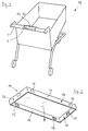
- the push handle 1 shown in FIG. 1 is on a shopping cart designed trolley 17 mounted.
- the push handle 1 is a plastic part designed and has a cover part in addition to handle sections 11 lockable device 2, which is used to hold an advertising medium 16 is determined.
- On the push handle 1, other useful Devices may be arranged.
- the insertion of a transponder is just as possible as that Equipment of push handle 1 with a paper clip.
- the facility 2 is designed as a kind of depression, which has a rectangular floor plan.
- a cover part 11 removably closes the device 2.
- the cover part 11 which can be placed on the device 2 from above. You can see from below into the transparent, plastic cover 11.
- the cover 11 has almost the same layout as that Device 2.
- On the usually flat plate-shaped back 12 closes a circumferential, the back 12 bounding on all sides Edge bar 13, which is directed downwards.
- In the sidebar 13 Locking means in the form of spaced wells or Breakthroughs 15 are provided.
- the cover part 11 is designed like a tub, which faces down with its open side.
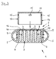
- FIG. 3 shows the device 2 in a section transverse to the longitudinal direction of the push handle 1. It is designed as a depression, from the bottom 3 of which webs 7 pointing upward extend, on the upper boundary 8 of which a strip-shaped advertising medium 16 lies.
- the two outermost webs 7 shown in the picture are designed as resilient locking tongues 9.
- the latching tongues 9, like the depressions or openings 15, are suitable latching means which are located in the device 2 and thus on the push handle 1.
- the drawing shows how the cover part 11 is placed on the device 2.
- the edge strip 13 points downward and is in the fitted state of the cover part 11 between the latching tongues 9 and the wall 5 delimiting the device 2. During the placement process, the latching tongues 9 engage with projections 10 in the depressions or openings 15 in the cover part 11.
- the cover part 11 is keyed to the device 2 and thus to the sliding device 1 in such a way that it cannot be detached by hand without additional aids, because it is also flush on all sides with the upper edge 4 of the device 2.
- the cover part 11 is dimensioned such that between the peripheral edge strip 13 and the peripheral wall 5 of the device 2, only an extremely small, even zero gap is formed. Ingressing rainwater seeps down on the outer walls 14 of the edge strip 13 and flows down through openings 6, which are located at the bottom 3 of the device 2, out of the push handle 1. Since the advertising medium 16 rests on the webs 7, no rain water can reach the advertising medium 16, which could have a detrimental effect on the advertising medium 16.
- the cover part 11 can be pulled upwards away from the device 2 by using suction cups and applying a certain force.
- the projections 10 on the catches 9 are designed such that they jump out of the depressions or openings 15 above a certain tensile force transmitted by the suction cups, so that the cover part 11 can be lifted off.
Landscapes
- Engineering & Computer Science (AREA)
- Chemical & Material Sciences (AREA)
- Combustion & Propulsion (AREA)
- Transportation (AREA)
- Mechanical Engineering (AREA)
- Handcart (AREA)
- Steering Devices For Bicycles And Motorcycles (AREA)
- Walking Sticks, Umbrellas, And Fans (AREA)
Applications Claiming Priority (2)
| Application Number | Priority Date | Filing Date | Title |
|---|---|---|---|
| DE29803064U | 1998-02-21 | ||
| DE29803064U DE29803064U1 (de) | 1998-02-21 | 1998-02-21 | Schiebegriff für einen Transportwagen |
Publications (3)
| Publication Number | Publication Date |
|---|---|
| EP0937626A2 true EP0937626A2 (fr) | 1999-08-25 |
| EP0937626A3 EP0937626A3 (fr) | 2001-07-04 |
| EP0937626B1 EP0937626B1 (fr) | 2003-05-21 |
Family
ID=8053037
Family Applications (1)
| Application Number | Title | Priority Date | Filing Date |
|---|---|---|---|
| EP99100161A Expired - Lifetime EP0937626B1 (fr) | 1998-02-21 | 1999-01-07 | Piognée pour pousser d'un chariot de transport |
Country Status (3)
| Country | Link |
|---|---|
| EP (1) | EP0937626B1 (fr) |
| DE (2) | DE29803064U1 (fr) |
| ES (1) | ES2199485T3 (fr) |
Cited By (2)
| Publication number | Priority date | Publication date | Assignee | Title |
|---|---|---|---|---|
| ES2232261A1 (es) * | 2002-12-16 | 2005-05-16 | Hipersystem, S.L. | Mango-consigna para carro de compra. |
| CN116507813A (zh) * | 2020-10-26 | 2023-07-28 | 旺众有限及股份两合公司 | 把手盖 |
Families Citing this family (3)
| Publication number | Priority date | Publication date | Assignee | Title |
|---|---|---|---|---|
| DE202006002938U1 (de) * | 2006-02-22 | 2007-07-05 | Sonnendorfer, Horst | Einkaufswagen mit Transponder |
| DE102007015268A1 (de) | 2007-03-27 | 2008-10-02 | Wanzl Metallwarenfabrik Gmbh | Schiebegriff |
| DE102008009686B4 (de) | 2008-02-18 | 2018-11-22 | Wanzl Metallwarenfabrik Gmbh | Schiebegriff |
Family Cites Families (5)
| Publication number | Priority date | Publication date | Assignee | Title |
|---|---|---|---|---|
| DE8502781U1 (de) * | 1985-02-01 | 1985-06-13 | Brüder Siegel GmbH & Co KG Draht- und Metallwarenfabrik, 8874 Leipheim | Schiebegriffvorrichtung für Einkaufswagen |
| DE3528898A1 (de) * | 1985-08-12 | 1987-02-19 | Siegel Geb Gmbh Co Kg | Schiebegriffvorrichtung fuer einkaufswagen |
| DE8601412U1 (de) * | 1986-01-21 | 1986-11-20 | Rudolf Wanzl Kg, 8874 Leipheim | Informations-Display |
| DE9317500U1 (de) * | 1993-11-16 | 1993-12-23 | Wanzl Gmbh & Co. Entwicklungs-Kg, 89340 Leipheim | Schiebegriffanordnung für einen Transportwagen |
| DE9419042U1 (de) * | 1994-11-26 | 1995-01-26 | Wanzl Gmbh & Co. Entwicklungs-Kg, 89340 Leipheim | Schiebegriffanordnung für einen Transportwagen |
-
1998
- 1998-02-21 DE DE29803064U patent/DE29803064U1/de not_active Expired - Lifetime
-
1999
- 1999-01-07 DE DE59905598T patent/DE59905598D1/de not_active Expired - Lifetime
- 1999-01-07 EP EP99100161A patent/EP0937626B1/fr not_active Expired - Lifetime
- 1999-01-07 ES ES99100161T patent/ES2199485T3/es not_active Expired - Lifetime
Cited By (3)
| Publication number | Priority date | Publication date | Assignee | Title |
|---|---|---|---|---|
| ES2232261A1 (es) * | 2002-12-16 | 2005-05-16 | Hipersystem, S.L. | Mango-consigna para carro de compra. |
| ES2232261B1 (es) * | 2002-12-16 | 2006-07-01 | Hipersystem, S.L. | Mango-consigna para carro de compra. |
| CN116507813A (zh) * | 2020-10-26 | 2023-07-28 | 旺众有限及股份两合公司 | 把手盖 |
Also Published As
| Publication number | Publication date |
|---|---|
| DE59905598D1 (de) | 2003-06-26 |
| ES2199485T3 (es) | 2004-02-16 |
| EP0937626A3 (fr) | 2001-07-04 |
| DE29803064U1 (de) | 1998-08-20 |
| EP0937626B1 (fr) | 2003-05-21 |
Similar Documents
| Publication | Publication Date | Title |
|---|---|---|
| EP0985200B1 (fr) | Poignee | |
| EP0937626B1 (fr) | Piognée pour pousser d'un chariot de transport | |
| DE4200861C2 (de) | Einrichtung zum Einkaufen von Ware in einem Selbstbedienungsgeschäft oder zum Transport von Reisegepäck | |
| EP2072371A2 (fr) | Chariot de transport empilable | |
| DE2549306A1 (de) | Verbesserter kunststoff-flaschenkasten mit verriegelungsvorrichtung | |
| DE102007015268A1 (de) | Schiebegriff | |
| EP0515979A1 (fr) | Chariot, particulièrement chariot d'achat | |
| DE3519960A1 (de) | Transport-handwagen | |
| DE102022111697A1 (de) | Transportvorrichtung und Verwendung derselben zum Transport zumindest eines Sterilgutbehälters | |
| EP0701518A1 (fr) | Plaque a pinces | |
| DE29503545U1 (de) | Vorrichtung zum Transport von Gegenständen | |
| DE29510138U1 (de) | Einkaufswagen sowie Schreibpult für Einkaufswagen | |
| EP3663230A1 (fr) | Conteneur de transport | |
| DE29919508U1 (de) | Tragevorrichtung für Flaschen | |
| DE202017100481U1 (de) | Profilmatte mit Griffelement | |
| DE1944527C (de) | Karteikasten | |
| EP3090642A1 (fr) | Insert pour monnaie de consigne | |
| DE4226375A1 (de) | Abfallbehälter-Anordnung | |
| AT409016B (de) | Vorrichtung zum abdecken einer wandöffnung in einem gebäude | |
| DE1944527B (de) | Karteikasten | |
| DE9308624U1 (de) | Einkaufswagen mit Pfandschloß | |
| DE19522182A1 (de) | Pfandmarke | |
| DE19915501A1 (de) | Pfandkarte, Schlüsselkarte, Kreditkarte und/oder Identitätskarte | |
| DE19963058A1 (de) | Gestell zum Abstellen von mobil einsetzbaren Verkehrsschildern | |
| DE102007058354A1 (de) | Systemmöbel |
Legal Events
| Date | Code | Title | Description |
|---|---|---|---|
| PUAI | Public reference made under article 153(3) epc to a published international application that has entered the european phase |
Free format text: ORIGINAL CODE: 0009012 |
|
| AK | Designated contracting states |
Kind code of ref document: A2 Designated state(s): DE ES FR GB IT |
|
| AX | Request for extension of the european patent |
Free format text: AL;LT;LV;MK;RO;SI |
|
| PUAL | Search report despatched |
Free format text: ORIGINAL CODE: 0009013 |
|
| AK | Designated contracting states |
Kind code of ref document: A3 Designated state(s): AT BE CH CY DE DK ES FI FR GB GR IE IT LI LU MC NL PT SE |
|
| AX | Request for extension of the european patent |
Free format text: AL;LT;LV;MK;RO;SI |
|
| RIC1 | Information provided on ipc code assigned before grant |
Free format text: 7B 62B 5/06 A, 7B 62B 3/14 B |
|
| 17P | Request for examination filed |
Effective date: 20010613 |
|
| AKX | Designation fees paid |
Free format text: DE ES FR GB IT |
|
| 17Q | First examination report despatched |
Effective date: 20020924 |
|
| GRAH | Despatch of communication of intention to grant a patent |
Free format text: ORIGINAL CODE: EPIDOS IGRA |
|
| GRAH | Despatch of communication of intention to grant a patent |
Free format text: ORIGINAL CODE: EPIDOS IGRA |
|
| GRAA | (expected) grant |
Free format text: ORIGINAL CODE: 0009210 |
|
| AK | Designated contracting states |
Designated state(s): DE ES FR GB IT |
|
| REG | Reference to a national code |
Ref country code: GB Ref legal event code: FG4D Free format text: NOT ENGLISH |
|
| REF | Corresponds to: |
Ref document number: 59905598 Country of ref document: DE Date of ref document: 20030626 Kind code of ref document: P |
|
| GBT | Gb: translation of ep patent filed (gb section 77(6)(a)/1977) | ||
| ET | Fr: translation filed | ||
| REG | Reference to a national code |
Ref country code: ES Ref legal event code: FG2A Ref document number: 2199485 Country of ref document: ES Kind code of ref document: T3 |
|
| PLBE | No opposition filed within time limit |
Free format text: ORIGINAL CODE: 0009261 |
|
| STAA | Information on the status of an ep patent application or granted ep patent |
Free format text: STATUS: NO OPPOSITION FILED WITHIN TIME LIMIT |
|
| 26N | No opposition filed |
Effective date: 20040224 |
|
| PG25 | Lapsed in a contracting state [announced via postgrant information from national office to epo] |
Ref country code: IT Free format text: LAPSE BECAUSE OF NON-PAYMENT OF DUE FEES Effective date: 20050107 |
|
| REG | Reference to a national code |
Ref country code: FR Ref legal event code: PLFP Year of fee payment: 18 |
|
| REG | Reference to a national code |
Ref country code: FR Ref legal event code: PLFP Year of fee payment: 19 |
|
| REG | Reference to a national code |
Ref country code: FR Ref legal event code: PLFP Year of fee payment: 20 |
|
| PGFP | Annual fee paid to national office [announced via postgrant information from national office to epo] |
Ref country code: GB Payment date: 20180125 Year of fee payment: 20 Ref country code: DE Payment date: 20180131 Year of fee payment: 20 Ref country code: ES Payment date: 20180220 Year of fee payment: 20 |
|
| PGFP | Annual fee paid to national office [announced via postgrant information from national office to epo] |
Ref country code: FR Payment date: 20180124 Year of fee payment: 20 |
|
| REG | Reference to a national code |
Ref country code: DE Ref legal event code: R071 Ref document number: 59905598 Country of ref document: DE |
|
| REG | Reference to a national code |
Ref country code: GB Ref legal event code: PE20 Expiry date: 20190106 |
|
| PG25 | Lapsed in a contracting state [announced via postgrant information from national office to epo] |
Ref country code: GB Free format text: LAPSE BECAUSE OF EXPIRATION OF PROTECTION Effective date: 20190106 |
|
| REG | Reference to a national code |
Ref country code: ES Ref legal event code: FD2A Effective date: 20220103 |
|
| PG25 | Lapsed in a contracting state [announced via postgrant information from national office to epo] |
Ref country code: ES Free format text: LAPSE BECAUSE OF EXPIRATION OF PROTECTION Effective date: 20190108 |