EP0937647B1 - Dispositif pour cercler des marchandises avec une bande de cerclage - Google Patents
Dispositif pour cercler des marchandises avec une bande de cerclage Download PDFInfo
- Publication number
- EP0937647B1 EP0937647B1 EP99108836A EP99108836A EP0937647B1 EP 0937647 B1 EP0937647 B1 EP 0937647B1 EP 99108836 A EP99108836 A EP 99108836A EP 99108836 A EP99108836 A EP 99108836A EP 0937647 B1 EP0937647 B1 EP 0937647B1
- Authority
- EP
- European Patent Office
- Prior art keywords
- looping
- strap
- air
- strapping
- guide
- Prior art date
- Legal status (The legal status is an assumption and is not a legal conclusion. Google has not performed a legal analysis and makes no representation as to the accuracy of the status listed.)
- Expired - Lifetime
Links
- 238000003780 insertion Methods 0.000 claims description 9
- 230000037431 insertion Effects 0.000 claims description 9
- 238000003466 welding Methods 0.000 claims description 9
- 229920001169 thermoplastic Polymers 0.000 claims description 4
- 239000004416 thermosoftening plastic Substances 0.000 claims description 2
- 238000011144 upstream manufacturing Methods 0.000 claims 1
- 230000000694 effects Effects 0.000 description 4
- 239000002184 metal Substances 0.000 description 3
- 230000001154 acute effect Effects 0.000 description 2
- 238000010276 construction Methods 0.000 description 2
- 238000004049 embossing Methods 0.000 description 2
- 238000002372 labelling Methods 0.000 description 2
- 230000007246 mechanism Effects 0.000 description 2
- 238000000034 method Methods 0.000 description 2
- 230000002441 reversible effect Effects 0.000 description 2
- 238000004804 winding Methods 0.000 description 2
- 230000009286 beneficial effect Effects 0.000 description 1
- 239000011230 binding agent Substances 0.000 description 1
- 230000003111 delayed effect Effects 0.000 description 1
- 230000008921 facial expression Effects 0.000 description 1
- 238000004519 manufacturing process Methods 0.000 description 1
- 238000004806 packaging method and process Methods 0.000 description 1
- 238000003860 storage Methods 0.000 description 1
- 230000003319 supportive effect Effects 0.000 description 1
- 239000012815 thermoplastic material Substances 0.000 description 1
Images

Classifications
-
- B—PERFORMING OPERATIONS; TRANSPORTING
- B65—CONVEYING; PACKING; STORING; HANDLING THIN OR FILAMENTARY MATERIAL
- B65B—MACHINES, APPARATUS OR DEVICES FOR, OR METHODS OF, PACKAGING ARTICLES OR MATERIALS; UNPACKING
- B65B13/00—Bundling articles
- B65B13/02—Applying and securing binding material around articles or groups of articles, e.g. using strings, wires, strips, bands or tapes
- B65B13/04—Applying and securing binding material around articles or groups of articles, e.g. using strings, wires, strips, bands or tapes with means for guiding the binding material around the articles prior to severing from supply
- B65B13/06—Stationary ducts or channels
Definitions
- the invention relates to a device for strapping packaged goods by means of a strapping consisting in particular of thermoplastic plastic with those specified in the preamble of claim 1 Characteristics.
- Such a strapping device is known from DE 33 03 956 A1. It has a machine table on which the packaged goods are transported by means of a Transport device in the form of a conveyor belt or a roller conveyor in a transport direction retractable into the strapping device and again can be moved out of it. Furthermore, a tape guide device provided on the machine table, by means of which the strapping as loose loop can be passed around the packaged goods. There is a tape guide frame for this provided in which a strap channel receiving the strapping is trained.
- thermoplastic strapping in the strap channel of the strap guide shot and then pulled tight around the packaged goods.
- a connection device in particular a The welding head, fixes the strapping around the packaged goods especially by welding the overlapping Strapping ends and separates the strap from the incoming strap stock from.
- the construction of the tape guide device discussed above brings Problems with the longitudinal strapping of packaged goods.
- Cross strapping in which the packaged goods in the opening of the cross and vertical
- the belt guide frame facing the transport direction is retracted unhindered the tape guide frame stands when strapping lengthways in the transport route of the packaged goods.
- they have the transport route crossing vertical leg of the tape guide frame can be pivoted away or be displaceable to the side, as indicated in DE 33 03 956 A1 is. This entails considerable design effort.
- a strapping device is known in which the strapping over a free distance in a band guide from Hand drawn and into a returning, funnel-shaped part of this tape guide must be re-threaded.
- the arrangement shown is for automatic strapping is completely unsuitable.
- GB-A-915 173 discloses a machine for securing a metal band, Wire or similar flexible binder around a container, box, Packaging or the like. Such a metal strip is between Guide sections pushed across a clear air gap, which is obvious done at a relatively slow speed since the metal band is withdrawn directly from a supply roll.
- the object of the invention based on a strapping device of the generic type with regard to further develop their tape guide device so that disturbing Frame parts of the belt guide device, for example in the transport route of the packaged standing frame parts, avoided and thereby one if possible trouble-free operation be guaranteed.
- the tape guide device in addition to guide channel sections in which the strapping at Shooting is mechanically guided in a conventional manner, at least has a free air gap above the machine table, over the strapping band when shooting into the band guiding device is led away.
- safety gear is to ensure for the one leading in when the strapping is shot in The beginning of the belt, which is preferably an inlet funnel acts.
- the additional belt drive devices provided in accordance with the labeling part in the inlet area of the guide channel sections for trouble-free guiding of the strapping around the packaged goods.
- the additional tape drive devices support the insertion of the the beginning of the strapping from the free air gap in the following guide channel section.
- the strapping when leading away Aided by compressed air over the at least one free air gap his. Due to this compressed air support, an air flow surrounds the band in the area of the free air gap that the band against Buckling stabilized.
- the compressed air nozzle arrangement provided according to claim 3 is generated a compressed air jet flowing along the respective free air path, the the strapping that runs through the air gap pneumatically.
- the nozzle arrangement preferably consists of two arranged side by side Compressed air nozzles, between which the strapping with its Flat sides is passed through the nozzles or from a annular compressed air nozzle (claims 4 and 5).
- Claims 7 and 9 and 10 identify alternative embodiments of the subject of the invention, particularly for longitudinal strapping machines are beneficial.
- a further technical measure in a Strapping device according to the invention may be provided to the rectilinear and precisely "overflowing" the strapping over to support the at least one free air gap. Accordingly, it is provided by a sudden braking of the strapping during leading his current band beginning over the at least a free air gap to create a stretching effect on the belt. Gives way the beginning of the band during its "overshoot" from a straight trajectory, so braking makes it practical stretched like a kind of "whip". For braking, for example The strapping mechanism of the strapping device can be stopped briefly.
- the strapping will be another supportive measure for a straightforward and precise "shooting away" of the strapping seized over the at least one free air gap.
- On fundamental problem with strapping especially made of thermoplastic Plastic is namely that these tapes on a Supply spool delivered in the wound state and in the strapping device be used. The tape is wound up by this a tendency to curve is impressed, which is expressed, for example, in that one unwound from the coil and left to itself Tape rolls up again in the direction of winding.
- a roller arrangement is according to claim 12 provided by which the strapping with alternating Directions of curvature is passed. After passing through this roller assembly would leave a strapping left to plan of documents and no tendency to curl up demonstrate. Consequently, the leading beginning of the tape also shows one treated in this way Strapping no longer has a tendency to deflect.
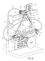
- FIG. 1 and 2 show partially broken away, schematic perspective representations of two different embodiments of a strapping device according to the invention.
- the strapping device shown in Fig. 1 is a longitudinal strapping machine and has a machine table 1 with a base 2 and a table surface 3. On the table surface 3 is a pair of parallel arranged conveyor belts to each other, of which in the Drawing only the conveyor belt 4 can be seen. With the help of these conveyor belts 4 is the packaged goods (not shown) - for example a stack of magazines - Can be moved into the strapping device in the direction of transport T. and can be pulled out of it again.
- a supply reel 5 for the strapping 6, an intermediate store 7, a shooting-in and retraction device 8 and a welding head 9 are provided below the table surface 3 .
- the launch and retraction facility 8 consists of a pair of drive rollers 10, which in a reversible electric motor 11 is driven in its direction of rotation. Otherwise are the tape storage with buffer 7, the shot and Retraction device 8 and the welding head 9 of a type such as that is common with strapping devices and therefore require in terms of their structure and function no further discussion.
- roller arrangement 45 is arranged by which the strapping 6 is passed through.
- the roller assembly 45 consists of a central embossing roller 46 and two with their circumference each a nip forming pressure rollers 47, 48 which on the in or. Outlet side of the roller arrangement 45 are arranged.
- This roller arrangement 45 serves - as explained - to level the strapping 6.
- the tape around the inlet-side pressure roller 47 with a Direction of curvature moved clockwise, then runs over the embossing roller 46 with a direction of curvature against the Clockwise and then again via the pressure roller on the outlet side 48 with a clockwise direction of curvature.
- the directions of curvature are impressed by the winding Curvature tendencies of the strapping 6 neutralized.
- the strapping device is designated as a whole by 12 Band guide device is provided, by means of which the strapping 6 as loose, vertical and aligned parallel to the transport direction T. Loop around the packaged goods retracted into the strapping position is feasible.
- This tape guide device 12 has a lower, Guide channel section 13 running parallel to the transport direction T. on, which is located below the table surface 3 in the machine table 1. Above the table surface 3 there is an upper one on gallows-shaped supports 14, 15 Guide channel section 16 arranged parallel to the lower guide channel section 13 runs and is aligned with it in the vertical direction. Both guide channel sections 13, 16 are in a known manner by in Cross-section U-shaped profile parts formed, in which the strapping 6th runs along.
- the band guide device 12 also has a free, vertically oriented air gap 17, 18 (indicated by dashed lines in the drawing) between the respectively associated ends 19, 20 or 21 or 22 of the lower and upper guide channel sections 13, 16.
- the strapping band 6 is guided with compressed air when it is shot into the band guiding device 12 via these two free air gaps 17, 18.
- compressed air nozzle arrangements 23, 24 are arranged at the outlet (end 19 or 21) of the lower or upper guide channel section 13 or 16, each of which has a compressed air jet flowing along the free air gap 17, 18 in the direction of the opposite guide channel section 13 or 16 Generate D o or D u .
- the nozzle arrangements 23, 24 each consist of two compressed air nozzles 25 arranged side by side, between which the strapping 6 is passed with its flat sides facing the nozzles 25.
- the air pressure nozzles 25 of the lower compressed air nozzle arrangement 23 at the end 19 of the lower guide channel section 13 are arranged below the table surface 3 and generate a vertically upward compressed air jet D o .
- the two other air pressure nozzles 25 of the compressed air nozzle arrangement 24 arranged at the end 21 of the upper guide channel section 16 are aligned in such a way that they produce a compressed air jet D u pointing downwards.
- the additional Belt drive devices 30, 31 and the nozzle arrangements 23, 24 controlled via a control device 34, the nozzle arrangements 23, 24 are connected in the usual way to a compressed air source and the Compressed air supply switched on and off by solenoid valves becomes.
- the valves are shown in the drawing for the sake of clarity omitted. It is only the control lines that control the valves 35, 36 and the two control lines 37, 38 for the additional Tape drive devices 30, 31 indicated.
- the drive roller pair 10 of the insertion and retraction device 8 is actuated and the strapping tape 6 is inserted from the buffer store 7 into the lower guide channel section 13 of the belt guide device 12 the welding head 9 is passed in the shooting-in direction E and, after its deflection, enters the air gap 17 at the end 19 of the lower guide channel section 13.
- the tape drive device 30 was already set in motion beforehand, so that the leading tape start is picked up by the drive roller pair 33 and the strapping tape 6 is shot into the upper guide channel section 16.
- the compressed air supply to the nozzle arrangement 23 can be switched off since the pneumatic guidance of the strapping 6 along the air gap 17 is no longer required.
- the strand of the strapping 6 passing through the air gap 17 is pulled by the belt drive device 30.
- the strapping 6 After the leading beginning of the band has passed through the upper guide channel section 16 with its deflection at the end 21, the strapping 6 enters the second air gap 18, which it runs vertically from top to bottom. Before entering, the nozzle arrangement 24 there was already activated, so that the downward compressed air jet D u in turn guides the strip. In the accompanying drawing, a snapshot is practically recorded, which shows the strapping 6 as it travels through the air gap 18 with its leading strap 39. In this context, it should be mentioned that in order to support a straight trajectory of the leading band start 39 over the free air gap 17 or 18, the strapping 6 can be delayed, for example, by sudden braking of the drive roller pair 33. An effect which can best be described as a "whip effect" occurs, through which the running band beginning 39 - if it was deflected from the imaginary straight line along the free air gap 17 or 18 - again stretches due to its inertia.
- the beginning of the tape begins 39 in the collecting opening 27, the strapping 6 is from the Tape drive device 31 is detected and further into the lower guide channel section 13 transported until the leading tape start 39 in the Welding head 9 enters.
- the drive roller pairs 10, 33 switched off, the leading band start held in the welding head and the drive roller pair 10 with reverse direction of rotation in Operation set.
- the upper and lower guide channel sections 13 and 16 open and those facing the inside Rolls of the drive roller pairs 33 pivoted away. This allows the strapping 6 freely emerge from the tape guide device 12 and lay tightly around the packaged goods.
- the retracted strand of the strapping 6 is stored in the buffer 7.
- the welding head 9 activated.
- the strapping parts overlapping there are joined together welded and separated from the tape supply.
- the packaged goods are thus strapped lengthways and can by means of the conveyor belts 4 in the transport direction T from the Strapping device can be moved out.
- the collecting openings 26, 27 form Funnel parts have slots 40 on their inside through which the strapping 6 can step through when withdrawing.
- the strapping device shown in FIG. 2 is again around a longitudinal strapping machine, the construction of which except for the following described differences corresponds to that of the device of FIG. 1. Matching components are therefore again with the same reference numerals Mistake.
- FIG Longitudinal strapping machine On its gallows-shaped supports 14, 15 a Longitudinal strut 42, on the center of which a funnel-shaped collecting opening 26 ' is arranged for the strapping 6.
- the latter is thus centrally above of the machine table 1 in a common vertical plane the lower guide channel section 13. Due to the offset of the collecting opening 26 'with respect to the transport direction T with respect to the compressed air nozzle arrangement 23, the air gap 17 no longer runs vertically, but instead at an acute angle W to the machine table 1 in the above Vertical plane.
- a tape drive device 30 ' is connected to the collecting opening 26' as an intermediate drive, which in turn has an electric motor 32 'and a pair of drive rollers 33 '.
- the strapping 6 is shot into a buffer 43 and from there it arrives at that directly adjacent to the collecting opening 26 ' Compressed air nozzle arrangement 24 ', by means of which the strapping 6 in turn at an acute angle W 'to the machine table 1 in the mentioned Vertical plane towards the collecting opening 27 over the inclined Air gap 18 'is shot.
- the tape guide device 12 'of the The embodiment according to FIG. 2 shows the lower guide channel section already discussed 13 in the machine table 1 and the two on each free air gaps 17 ', 18' adjoining both ends at the top, who lead the strapping so that the at loose strapping loop formed when it was shot is in the form of a vertical triangle.
- the belt drive device 30 ' is otherwise with an additional roller 44th provided, to which the electric motor 32 'is switchable, so that it Intermediate drive formed both on the inlet side and on the outlet side works.
- the strapping device according to FIG. 2 operates in terms of its mode of operation comparable to that of FIG. 1, so that there is another explanation superfluous. It should also be noted that the strapping device according to 2 can be provided with a roller arrangement 45 as shown in Fig. 1.
Landscapes
- Engineering & Computer Science (AREA)
- Mechanical Engineering (AREA)
- Basic Packing Technique (AREA)
- Delivering By Means Of Belts And Rollers (AREA)
Claims (12)
- Dispositif de cerclage de marchandises avec une bande de cerclage en particulier en matière thermoplastique, comprenant :caractérisé en ce que, dans la région d'entrée (28, 29) des tronçons de canaux de guidage (13, 16), sont agencés des dispositifs d'entraínement de bande additionnels respectifs (30, 30', 31) à titre d'entraínement intermédiaire pour la bande de cerclage (6).un tablier de machine (1) sur lequel les marchandises peuvent être amenées dans le dispositif de cerclage au moyen d'une unité de transport (4), et peuvent à nouveau en être enlevées,un dispositif de guidage de bande (12) sur le tablier de machine (1), au moyen duquel la bande de cerclage (6) peut être passée autour des marchandises pour former une boucle lâche,un dispositif d'injection et de rétraction (8) pour injecter la bande de cerclage (6) dans le dispositif de guidage de bande (12), et pour tendre la bande de cerclage (6) autour des marchandises,un dispositif de jonction, en particulier un dispositif de soudage (9), afin de fixer la boucle de bande de cerclage tendue autour des marchandises, ledit dispositif de guidage de bande (12) comportant des tronçons de canaux de guidage (13, 16), dans lesquels la bande de cerclage (6) est guidée de façon mécanique lors de l'injection, d'une manière traditionnelle, et au moins un trajet libre (17, 18, 17', 18') au-dessus du tablier de machine (1), de sorte que la bande de cerclage (6) est projetée à travers le trajet libre (17, 18, 17', 18') lors de son injection dans le dispositif de guidage de bande (12), et à l'extrémité de chaque trajet libre (17, 18, 17', 18') est agencé un dispositif de saisie (26, 26', 27) pour l'amorce de bande (39) qui se présente en avant lors de l'injection de la bande de cerclage (6),
- Dispositif de cerclage selon la revendication 1, caractérisé en ce que la bande de cerclage (6) est guidée avec assistance d'air comprimé lors de son passage sur ledit au moins un trajet libre (17, 18, 17', 18').
- Dispositif de cerclage selon la revendication 2, caractérisé par un agencement à buses d'air comprimé (23, 24, 24') respectif au début dudit au moins un trajet libre (17, 18, 17', 18'), pour la production d'un jet d'air comprimé (Do, Du) qui s'écoule le long du trajet libre (17, 18, 17', 18') dans la direction d'injection (E).
- Dispositif de cerclage selon la revendication 3, caractérisé en ce que les agencements à buses (23, 24, 24') sont respectivement constitués par au moins deux buses à air comprimé (25) agencées l'une à côté de l'autre, entre lesquelles peut être passée la bande de cerclage (6), de sorte que ses côtés plans sont tournés vers les buses (25).
- Dispositif de cerclage selon l'une ou l'autre des revendications 3 et 4, caractérisé en ce que les agencements à buses comprennent respectivement une buse à air comprimé annulaire, à travers l'ouverture annulaire de laquelle peut être passée la bande de cercle (6).
- Dispositif de cerclage selon l'une des revendications 1 à 5, caractérisé en ce que le dispositif de saisie est réalisé sous la forme d'une ouverture de réception (26, 26', 27) en forme d'entonnoir.
- Dispositif de cerclage selon l'une des revendications 1 à 6, caractérisé en ce que le dispositif de guidage de bande (12) comprend :un tronçon de canal de guidage inférieur (13) dans le tablier de machine (1),un tronçon de canal de guidage supérieur (16) qui s'étend sensiblement parallèlement au premier, au-dessus du tablier de machine (1), etun tronçon libre vertical respectif (17, 18) entre les extrémités (19, 20, 21, 22) du tronçon de canal de guidage inférieur et du tronçon de canal de guidage supérieur (13, 16).
- Dispositif de cerclage selon la revendication 7, caractérisé en ce que les dispositifs d'entraínement de bande supplémentaires (30, 31) sont agencés respectivement dans les zones de renvoi au niveau des extrémités (20, 22) d'entrée du tronçon de canal de guidage inférieur et/ou du tronçon de canal de guidage supérieur (13, 16).
- Dispositif de cerclage selon l'une des revendications 1 à 6, caractérisé en ce que le dispositif de guidage de bande (12') comprend un tronçon de canal de guidage inférieur (13) dans le tablier de machine (1), et deux tronçons libres (17', 18') qui font respectivement suite vers le haut à ses deux extrémités, et qui sont ainsi agencés que la boucle de bande de cerclage lâche formée lors de l'injection de la bande de cerclage (6) se présente sensiblement sous la forme d'un triangle dressé verticalement.
- Dispositif de cerclage selon la revendication 9, caractérisé en ce que, dans la région de renvoi au sommet supérieur du tracé triangulaire de la bande de cerclage (6), est agencé un entraínement intermédiaire (30') avec accumulateur intermédiaire de bande (43), agissant à la fois du côté entrée et du côté sortie.
- Dispositif de cerclage selon l'une des revendications 1 à 10, caractérisé en ce que la bande de cerclage (6) est susceptible d'être tendue par freinage soudain pendant la traversée de son amorce de bande antérieure (39) sur ledit au moins un trajet libre (17, 18, 17', 18').
- Dispositif de cerclage selon l'une des revendications 1 à 11, caractérisé en ce qu'il est prévu en amont du dispositif d'injection et de rétraction (8) un agencement à rouleau (45) pour la rectification à plat de la bande de cerclage (6), à travers lequel la bande de cerclage (6) est passée avec des directions de courbure alternantes.
Applications Claiming Priority (3)
| Application Number | Priority Date | Filing Date | Title |
|---|---|---|---|
| DE19503112A DE19503112A1 (de) | 1995-02-01 | 1995-02-01 | Vorrichtung zum Umreifen von Packgut mit einem Umreifungsband |
| DE19503112 | 1995-02-01 | ||
| EP96100809A EP0725005B1 (fr) | 1995-02-01 | 1996-01-20 | Dispositif pour cercler des marchandises avec une bande de cerclage |
Related Parent Applications (2)
| Application Number | Title | Priority Date | Filing Date |
|---|---|---|---|
| EP96100809A Division-Into EP0725005B1 (fr) | 1995-02-01 | 1996-01-20 | Dispositif pour cercler des marchandises avec une bande de cerclage |
| EP96100809A Division EP0725005B1 (fr) | 1995-02-01 | 1996-01-20 | Dispositif pour cercler des marchandises avec une bande de cerclage |
Publications (2)
| Publication Number | Publication Date |
|---|---|
| EP0937647A1 EP0937647A1 (fr) | 1999-08-25 |
| EP0937647B1 true EP0937647B1 (fr) | 2001-07-25 |
Family
ID=7752819
Family Applications (2)
| Application Number | Title | Priority Date | Filing Date |
|---|---|---|---|
| EP96100809A Expired - Lifetime EP0725005B1 (fr) | 1995-02-01 | 1996-01-20 | Dispositif pour cercler des marchandises avec une bande de cerclage |
| EP99108836A Expired - Lifetime EP0937647B1 (fr) | 1995-02-01 | 1996-01-20 | Dispositif pour cercler des marchandises avec une bande de cerclage |
Family Applications Before (1)
| Application Number | Title | Priority Date | Filing Date |
|---|---|---|---|
| EP96100809A Expired - Lifetime EP0725005B1 (fr) | 1995-02-01 | 1996-01-20 | Dispositif pour cercler des marchandises avec une bande de cerclage |
Country Status (3)
| Country | Link |
|---|---|
| US (1) | US5680813A (fr) |
| EP (2) | EP0725005B1 (fr) |
| DE (3) | DE19503112A1 (fr) |
Families Citing this family (11)
| Publication number | Priority date | Publication date | Assignee | Title |
|---|---|---|---|---|
| DE19615009B4 (de) * | 1996-04-16 | 2005-09-29 | Smb Schwede Maschinenbau Gmbh | Kreuzleger mit Umreifungsvorrichtung |
| DE19920531C2 (de) * | 1999-05-05 | 2003-12-04 | Smb Schwede Maschb Gmbh | Verpackungsstraße für Zeitschriften, Magazine und dergleichen Druckprodukte |
| US6711883B2 (en) * | 1999-05-05 | 2004-03-30 | Smb Schwede Maschinenbau Gmbh | Strapping machine for strapping a stack of products |
| DE10010275A1 (de) | 2000-03-02 | 2001-09-13 | Schneider & Ozga | Vorrichtung insbesondere zum Längsumreifen von Packgut |
| DE20004062U1 (de) | 2000-03-03 | 2001-08-23 | Schneider & Ozga, 95463 Bindlach | Vorrichtung insbesondere zum Längsumreifen von Packgut |
| EP1207107B1 (fr) | 2000-11-20 | 2004-08-18 | Ferag AG | Dispositif de cerclage |
| EP1279597B1 (fr) | 2001-07-28 | 2004-10-06 | Schneider + Ozga | Dispositif de cerclage |
| DE10160718A1 (de) * | 2001-12-11 | 2003-06-26 | Klinger Maschb Gmbh | Vorrichtung und Verfahren zum Umreifen von Produkten |
| DE102004058830A1 (de) * | 2004-12-06 | 2006-06-08 | Smb Schwede Maschinenbau Gmbh | Umreifungsmaschine zum Umreifen eines Packgutes und insbesondere von Zeitschriftenstapeln |
| US20060168917A1 (en) * | 2005-01-31 | 2006-08-03 | Yizhak Ashkenazi | System and machine for strapping articles |
| DE102024121263A1 (de) | 2024-07-25 | 2026-01-29 | Arkistra GmbH | Vorrichtung und Verfahren zum Umreifen von palettiertem Packgut |
Family Cites Families (18)
| Publication number | Priority date | Publication date | Assignee | Title |
|---|---|---|---|---|
| US2913270A (en) * | 1954-12-13 | 1959-11-17 | Sr Gustav Sachsenroder | Knot-tying apparatus |
| US3086451A (en) * | 1959-10-01 | 1963-04-23 | Ver Metaalverpakking Mij Nv | Machines for securing a metal strap around a container, box, package or the like |
| CH388848A (de) * | 1959-10-29 | 1965-02-28 | Ver Metaalverpakking Mij Nv | Vorrichtung zum Befestigen eines Metallbandes oder eines Metalldrahtes um eine Kiste, eine Dose, ein Paket oder ein anderes Packstück |
| DE1174688B (de) * | 1959-10-29 | 1964-07-23 | Ver Metaalverpakking Mij Nv | Vorrichtung zum Befestigen eines Metallbandes oder eines Metalldrahtes um eine Kiste, eine Dose, ein Paket oder ein anderes Packstueck |
| DE1153318B (de) * | 1959-11-05 | 1963-08-22 | Ver Metaalverpakking Mij Nv | Maschine zum Befestigen eines Metallbandes oder eines Metalldrahtes um eine Kiste, eine Dose, ein Paket oder ein anderes Packstueck |
| CH382649A (de) * | 1959-11-05 | 1964-09-30 | Ver Metaalverpakking Mij N V | Maschine zum Befestigen eines Metallbandes oder eines Metalldrahtes um eine Kiste, eine Dose, ein Paket oder ein anderes Packstück |
| US3831512A (en) * | 1972-12-26 | 1974-08-27 | Interlake Inc | Strap feed track with fluid-actuated strap end positioning means |
| JPS5137600B2 (fr) * | 1973-05-24 | 1976-10-16 | ||
| GB2047194A (en) | 1979-04-19 | 1980-11-26 | Gerrard Ind Ltd | Luggage strapping apparatus |
| DE3303956C2 (de) | 1983-02-05 | 1987-08-20 | Berthold 7902 Blaubeuren Bührle | Vorrichtung zum Umreifen eines quaderförmigen Packgutes |
| FR2557536B3 (fr) * | 1983-12-28 | 1986-04-04 | Turroques Michel | Machine a ficeler permettant de nouer une ficelle autour d'un produit ou article, tel que boyau de charcuterie ou un sachet |
| NL8500540A (nl) * | 1985-02-26 | 1986-09-16 | Sollas Holland Bv | Inrichting voor het aanbrengen van een wikkelstrook rond een voorwerp. |
| DE3926679A1 (de) | 1989-08-12 | 1991-02-14 | Herbert Ferklass | Verfahren und vorrichtung zum banderolieren von waren |
| US5078057A (en) | 1990-01-05 | 1992-01-07 | Illinois Tool Works Inc. | Binding machine, such as strapping machine |
| CH681074A5 (fr) * | 1990-05-10 | 1993-01-15 | Hans Guettinger | |
| DE4024149C2 (de) * | 1990-07-30 | 1993-12-16 | Krupp Ag Hoesch Krupp | Vorrichtung zum horizontalen oder annähernd horizontalen Umreifen von Packstücken |
| JP2992568B2 (ja) * | 1990-09-04 | 1999-12-20 | 寛 畑谷 | テープによる結束装置 |
| DE4230730B4 (de) | 1992-09-14 | 2005-05-25 | Georg Lang | Umreifungsmaschine mit einem Bandführungsrahmen |
-
1995
- 1995-02-01 DE DE19503112A patent/DE19503112A1/de not_active Withdrawn
-
1996
- 1996-01-20 DE DE59604856T patent/DE59604856D1/de not_active Expired - Lifetime
- 1996-01-20 EP EP96100809A patent/EP0725005B1/fr not_active Expired - Lifetime
- 1996-01-20 EP EP99108836A patent/EP0937647B1/fr not_active Expired - Lifetime
- 1996-01-20 DE DE59607377T patent/DE59607377D1/de not_active Expired - Lifetime
- 1996-01-25 US US08/591,834 patent/US5680813A/en not_active Expired - Lifetime
Also Published As
| Publication number | Publication date |
|---|---|
| DE59604856D1 (de) | 2000-05-11 |
| EP0725005B1 (fr) | 2000-04-05 |
| EP0725005A1 (fr) | 1996-08-07 |
| EP0937647A1 (fr) | 1999-08-25 |
| DE59607377D1 (de) | 2001-08-30 |
| DE19503112A1 (de) | 1996-08-08 |
| US5680813A (en) | 1997-10-28 |
Similar Documents
| Publication | Publication Date | Title |
|---|---|---|
| DE4100276C2 (de) | Bandumreifungsmaschine | |
| DE69416401T2 (de) | Verfahren und vorrichtung zum herstellen und füllen von verpackungen | |
| EP0128334B1 (fr) | Procédé et dispositif pour le stockage intermédiaire des imprimés arrivant en formation imbriquée | |
| EP0725005B1 (fr) | Dispositif pour cercler des marchandises avec une bande de cerclage | |
| EP1541470B1 (fr) | Dispositif pour appliquer une bande de cerclage longitudinale autour d'un objet, comme en particulier une pile de journaux ou magazines | |
| EP0708049B1 (fr) | Dispositif de séparation d'une bande de papier | |
| DE3708267A1 (de) | Bandbogenfuehrung fuer eine umschnuerungsmaschine | |
| EP0681958B1 (fr) | Dispositif pour cercler plus spécialement des marchandises compressibles telles que des feuilles de carton ondulé ou similaires | |
| DE2320423A1 (de) | Vorrichtung zum kontinuierlichen zufuehren eines bandes | |
| DE4421661B4 (de) | Vorrichtung zum Längsumreifen eines Gut-Stapels von Zeitschriften, Magazinen, Kartonagen o. dgl. | |
| EP0680881B1 (fr) | Dispositif pour banderoler des objets | |
| DE19816510A1 (de) | Bahneinzugsvorrichtung für Rotationsdruckmaschinen | |
| WO1994006683A1 (fr) | Enrubaneuse munie d'un cadre de guidage de bandes | |
| DE4408568A1 (de) | Automatische Maschine zum Binden von Rohrbündeln oder ähnlichem | |
| WO2004002829A1 (fr) | Dispositif de cerclage | |
| DE19632728A1 (de) | Umreifungsvorrichtung | |
| EP0905025B1 (fr) | Dispositif de cerclage | |
| DE3425673A1 (de) | Verfahren und vorrichtung zum speichern von kontinuierlich, insbesondere in einer schuppenformation anfallenden erzeugnissen, insbesondere druckprodukten | |
| DE19611787C2 (de) | Anordnung zum Falzen von Bögen | |
| EP0143187A1 (fr) | Dispositif de nouage | |
| DE2065102C3 (de) | Vorrichtung zum Einwickeln zylindrischer Gegenstände | |
| DE20319152U1 (de) | Vorrichtung zum Längsumreifen eines Packstücks wie insbesondere eines Stapels von Zeitungen, Magazinen o.dgl. | |
| DE2507717C3 (de) | Führungskanal an einer Umschnürungsvorrichtung | |
| EP0695687B1 (fr) | Dispositif pour cercler des marchandises emballées | |
| CH635149A5 (de) | Daempfer zum behandeln einer kontinuierlich durchlaufenden textilbahn, die in ihm waehrend einer bestimmten verweilzeit der einwirkung von reaktionsmitteln ausgesetzt wird. |
Legal Events
| Date | Code | Title | Description |
|---|---|---|---|
| PUAI | Public reference made under article 153(3) epc to a published international application that has entered the european phase |
Free format text: ORIGINAL CODE: 0009012 |
|
| AC | Divisional application: reference to earlier application |
Ref document number: 725005 Country of ref document: EP |
|
| AK | Designated contracting states |
Kind code of ref document: A1 Designated state(s): DE FR GB IT SE |
|
| 17P | Request for examination filed |
Effective date: 19990723 |
|
| 17Q | First examination report despatched |
Effective date: 20000228 |
|
| GRAG | Despatch of communication of intention to grant |
Free format text: ORIGINAL CODE: EPIDOS AGRA |
|
| GRAG | Despatch of communication of intention to grant |
Free format text: ORIGINAL CODE: EPIDOS AGRA |
|
| GRAH | Despatch of communication of intention to grant a patent |
Free format text: ORIGINAL CODE: EPIDOS IGRA |
|
| GRAH | Despatch of communication of intention to grant a patent |
Free format text: ORIGINAL CODE: EPIDOS IGRA |
|
| GRAA | (expected) grant |
Free format text: ORIGINAL CODE: 0009210 |
|
| AC | Divisional application: reference to earlier application |
Ref document number: 725005 Country of ref document: EP |
|
| AK | Designated contracting states |
Kind code of ref document: B1 Designated state(s): DE FR GB IT SE |
|
| REF | Corresponds to: |
Ref document number: 59607377 Country of ref document: DE Date of ref document: 20010830 |
|
| GBT | Gb: translation of ep patent filed (gb section 77(6)(a)/1977) |
Effective date: 20011026 |
|
| ET | Fr: translation filed | ||
| REG | Reference to a national code |
Ref country code: GB Ref legal event code: IF02 |
|
| PLBE | No opposition filed within time limit |
Free format text: ORIGINAL CODE: 0009261 |
|
| STAA | Information on the status of an ep patent application or granted ep patent |
Free format text: STATUS: NO OPPOSITION FILED WITHIN TIME LIMIT |
|
| 26N | No opposition filed | ||
| PGFP | Annual fee paid to national office [announced via postgrant information from national office to epo] |
Ref country code: SE Payment date: 20110121 Year of fee payment: 16 Ref country code: FR Payment date: 20110201 Year of fee payment: 16 Ref country code: IT Payment date: 20110126 Year of fee payment: 16 |
|
| PGFP | Annual fee paid to national office [announced via postgrant information from national office to epo] |
Ref country code: DE Payment date: 20110324 Year of fee payment: 16 Ref country code: GB Payment date: 20110121 Year of fee payment: 16 |
|
| REG | Reference to a national code |
Ref country code: SE Ref legal event code: EUG |
|
| GBPC | Gb: european patent ceased through non-payment of renewal fee |
Effective date: 20120120 |
|
| REG | Reference to a national code |
Ref country code: FR Ref legal event code: ST Effective date: 20120928 |
|
| PG25 | Lapsed in a contracting state [announced via postgrant information from national office to epo] |
Ref country code: GB Free format text: LAPSE BECAUSE OF NON-PAYMENT OF DUE FEES Effective date: 20120120 Ref country code: SE Free format text: LAPSE BECAUSE OF NON-PAYMENT OF DUE FEES Effective date: 20120121 Ref country code: DE Free format text: LAPSE BECAUSE OF NON-PAYMENT OF DUE FEES Effective date: 20120801 |
|
| REG | Reference to a national code |
Ref country code: DE Ref legal event code: R119 Ref document number: 59607377 Country of ref document: DE Effective date: 20120801 |
|
| PG25 | Lapsed in a contracting state [announced via postgrant information from national office to epo] |
Ref country code: IT Free format text: LAPSE BECAUSE OF NON-PAYMENT OF DUE FEES Effective date: 20120120 |
|
| PG25 | Lapsed in a contracting state [announced via postgrant information from national office to epo] |
Ref country code: FR Free format text: LAPSE BECAUSE OF NON-PAYMENT OF DUE FEES Effective date: 20120131 |